This is article 3 of the Building a Radio Series, before we looked at the general project overview, along with how the Arduino was hooked up. Now we will be looking at the PC hardware along with the code being used to do all the music.
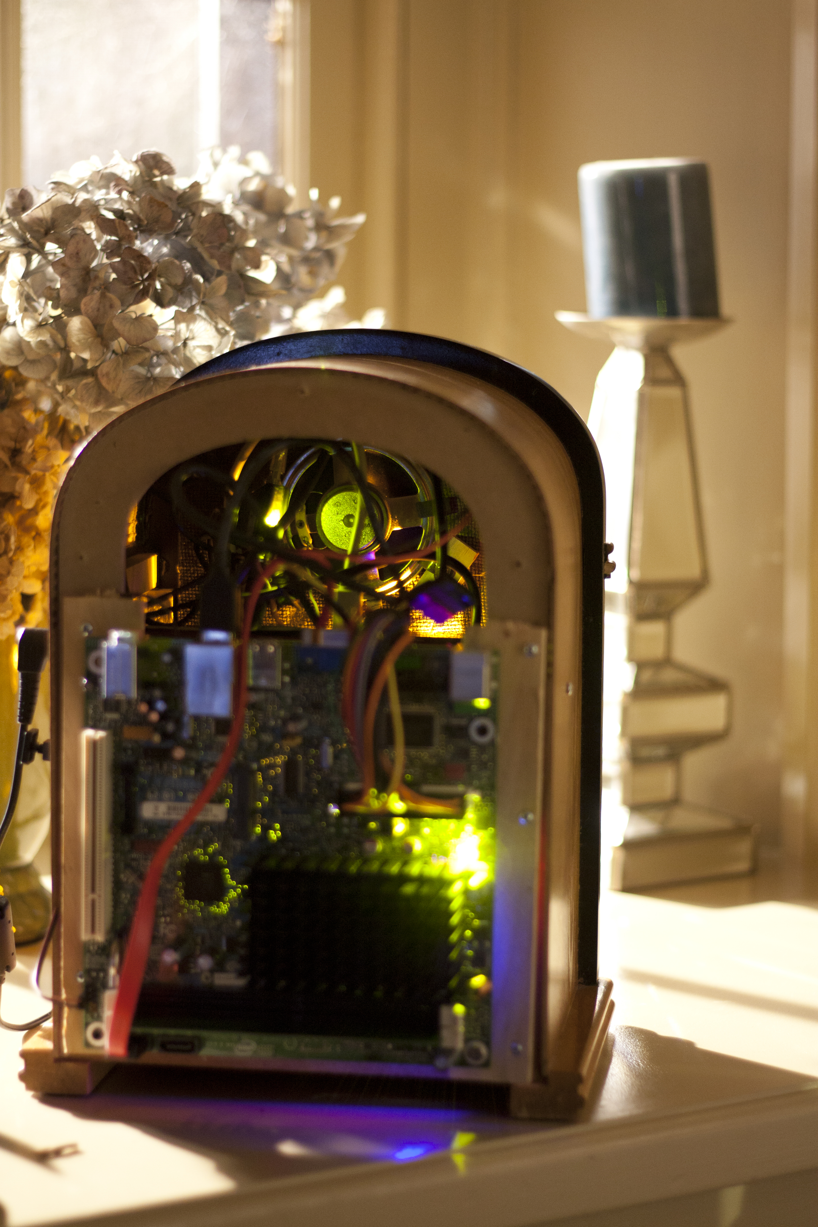

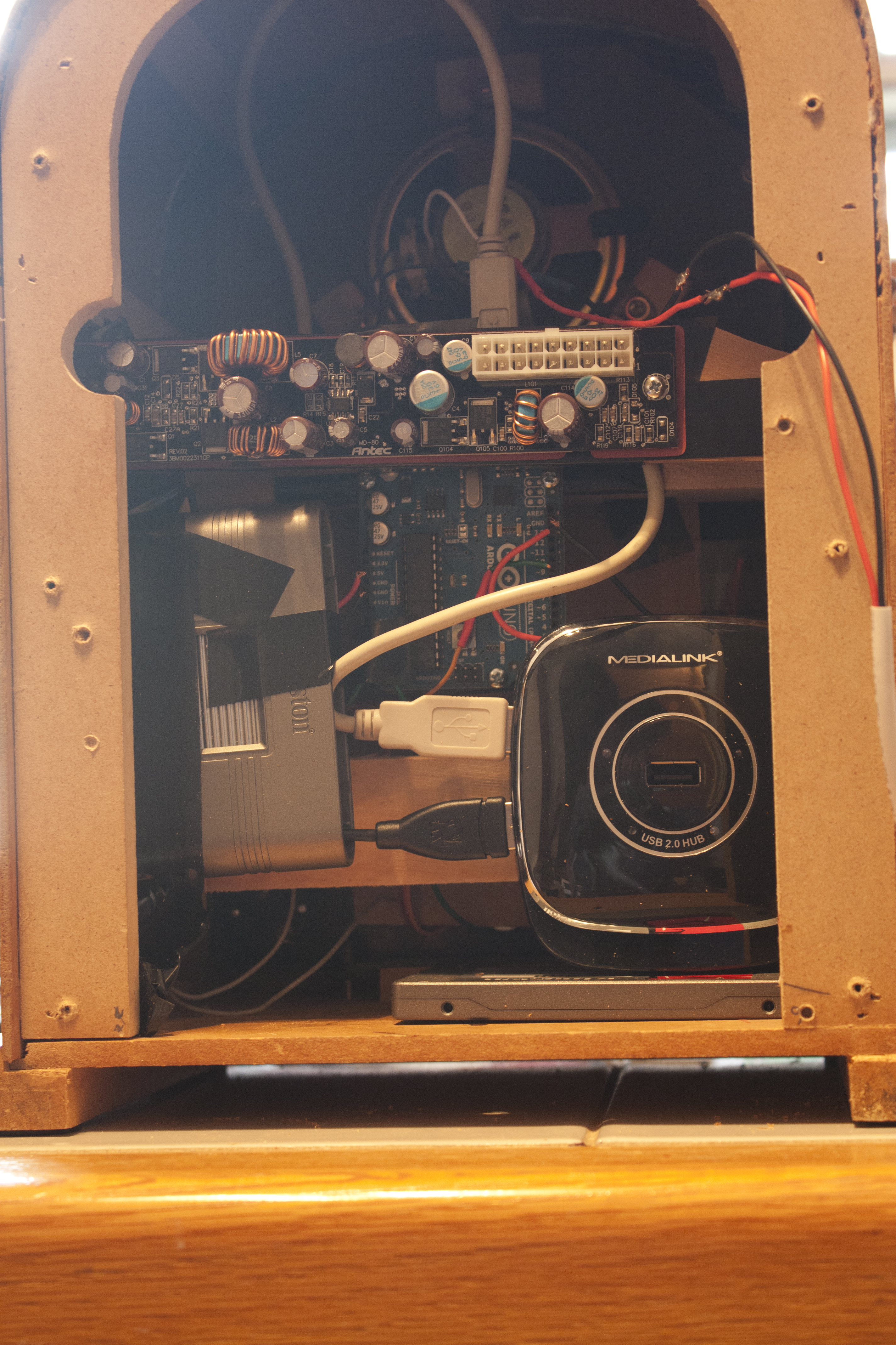
I was afraid that this project world have one critical weakness, that the pc running the show would end up taking a while to start up; making the whole thing slow and by the time it came up you didn’t want to use it. I ended up getting Intel D510MO, but any computer that runs Windows would do. To save myself from having to write my own music player/interface over a music player this project relied on Windows Media Player using C#. This made it really quick and easy to build the DJ software. Mine had 1GB of ram, and an 8GB Kingston SSD (model S100S2/8G), and a Kingston 19-in-1 media card reader. There was a USB hub in there so it could be just 1 USB cable instead of 2.
I have a MSDN account so I was able to get Windows XP really easily, it theoretically could have been Windows 2000 or newer, but I was worried about drivers for Windows 2000, so I went with the next lightest OS. I went through and cleaned it out a lot, disabling parts of Windows I didn’t need; there are a lot of guides online to speed up Windows XP. Just make sure Windows Media Player is on whatever OS you use, I was developing on Windows 7 Enterprise and it didn’t have it. I freaked out will I realized I just had to go to Add/Remove Programs -> Windows Components and add it. As mentioned in the earlier article, the speaker in the unit went to a USB sound card. The USB sound card ended up being a good amount louder than the built-in sound card. The code adjusts the Media Player sound volume, not Windows volume.
The software is commented, so if you are interested in depth, you may want to scroll down and download that. But a quick overview, the program scans for removable cards, and then it scans them for the folder structure it uses. 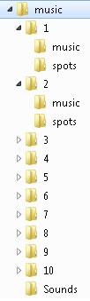 Then if there is only one card that meets these criteria mounts it as its source. Then it goes to the com port that is saved in a settings file in the same location of the program. If the interface is used to change the interface it should change it in the settings file. One problem is I was under the clock in this project, thus my usual extensive testing wasn’t done; it is possible bugs exist, but I think I found all the big ones.
A thread is spawned off to get input from the knobs, this is a separate thread so it can change settings while other things are going on. It reads the input from the Arduino, and makes adjustments when needed. In the boot process it gets the channel number so that the radio knows where to build a playlist out of. It gets the songs, mixes them up then adds them to a list, it then grabs all the “spots” mixes them up and puts one in every 4 songs. After all this 30 minutes of static is put in; in theory once that starts there is a 30 minute timer to shutdown.
That is the basic view of the software; the code is available below, with comment that anyone can have fun with. Any questions can be emailed and/or posted on the blog. This wraps up the Building a Radio series, unless I think of anything else to put up about it. If anyone has a idea of another project shoot me a email.
(LINKS)