Background
I have always loved devices. Growing up, my parents would have a Blackberry or before that Palm Pilot, and I thought they were amazing. Seeing my interest, my parents got me a Cybiko Xtreme. A PDA designed for teens and college kids. With games, books, apps, and even wireless communications, all of this in 2001! The device and company have an interesting history:
To quote Rameriez in 2002 (https://everything2.com/title/Cybiko):
With Yang’s surname, the made in Taiwan sticker on the back, and Japanese name (Cybiko means Cyber-Girl in Japanese), you’d be forgiven for mistaking this as an asian product. But, the Cybiko was designed, programmed and tested in Russia.
“They don’t exactly hide the fact that Cybiko’s Russian, but let’s say, they don’t highlight it either.”
(Vaidyanathan Sivakumar, Fund Manager)
There were three iterations of the Cybiko. V1, V2, and Xtreme. The V1 and V2 look very similar. V2 saved some money by cutting the RAM in half. The Xtreme had a whole different look and upgraded the memory and CPU. All of them had a radio operating at ~900 MHz. Some features were really ahead of their time with wireless chat and being able to have one device act as a base station giving other devices E-Mail, or WAP web browsing. You could download E-Mail over serial for V1/V2 and mini-USB for Xtreme to later manually sync back. All of this for around $100 in 2001 or $185 today. There was also an MP3 player add-on for the devices, allowing earlier MP3 usage.
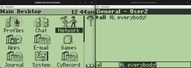
I had an Xtreme with the MP3 player add-on. Being able to play music, games, and go on primitive WAP web pages in 2001 was awesome. There was also a client for AOL Instant Messenger. I could sit in bed and chat with friends from school. In the era of the giant family desktops in the living room, this was a big upgrade!
Goal
Having one of the devices from my childhood and wanting to play around with it more, I found that MAME has an emulator for it created by Tim Schuerewegen around 2001-2007. He did a fantastic job keeping the device alive for people. He’s also active in the Cybiko Discord and wrote a newer web version that I encourage anyone wanting to play around with it to try!
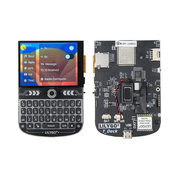
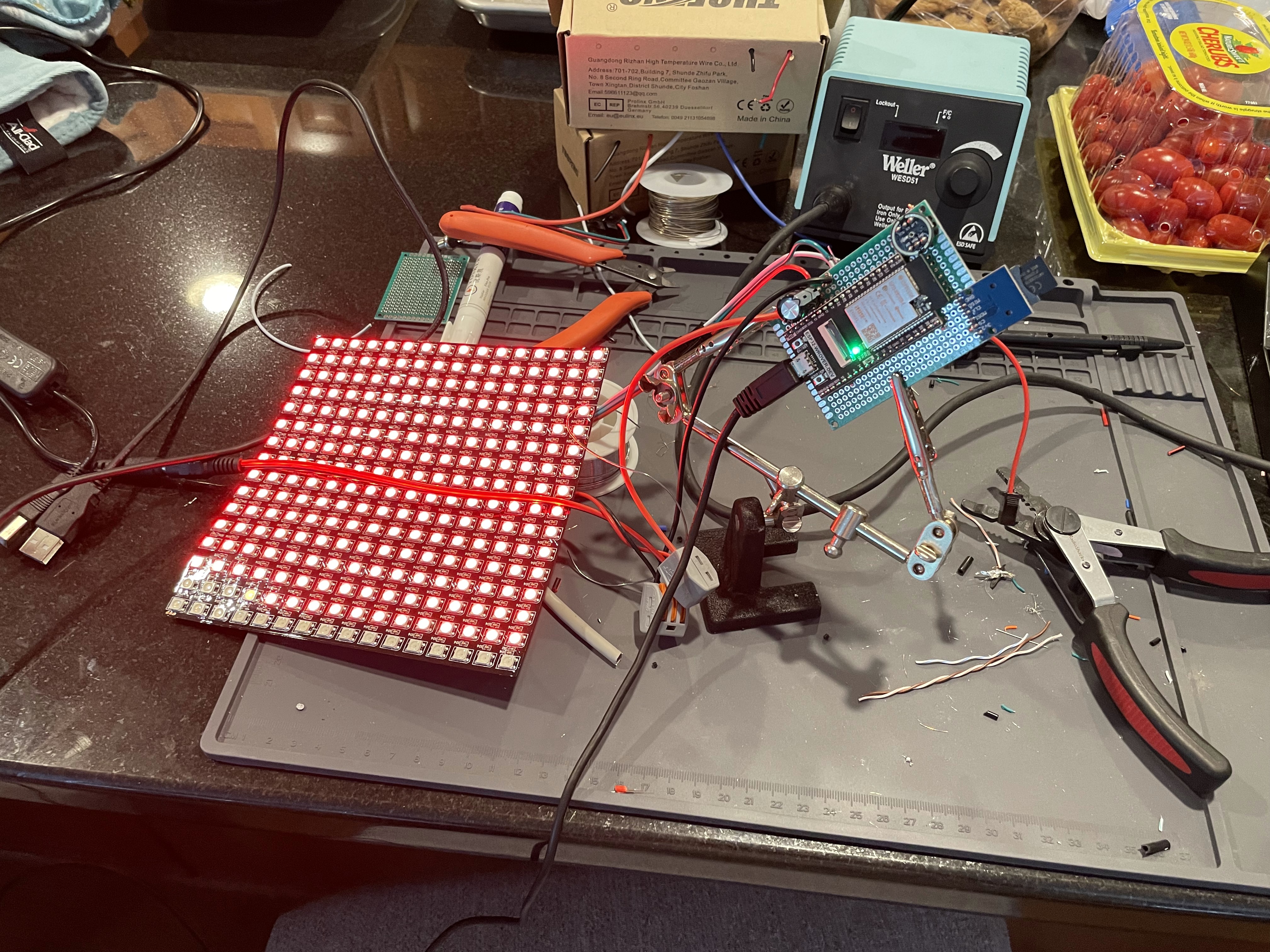
I have been playing with the ESP32, and then found the LilyGo T-Deck, I wanted to see if I could port an emulator onto the device and how close to a full Cybiko it could be. That started me down a path of researching the MAME code and seeing if I could extract enough out for a functioning emulator.
Planning
MAME is an amazing system with many layers to its backend. It has many different CPUs, screens, chipsets emulated, and you can create a new device connecting these different pieces. The issue is that all of that is overhead and on our tiny ESP32, I knew I would need to strip it down as far as I could, and at that point I was basically making a new emulator. I’m also not the best at C, and figured if I was going to make a new emulator I would want to start in Java, then if/when there were issues, I could much more easily diagnose them. There is the downside that Java is slower than some other languages. The Cybiko Xtreme ran at 18 MHz and with its slow black and white screen I figured it would be ok for now. I ended up adding some code where the console outputs how close to real time the frame was delivered, and on my old laptop, frames were ready well before they were needed.
And that is where this project stalled for a while. Creating a new emulator is a giant task, and I didn’t have the time to spend, which I guessed would be weeks, if not months. Enter Claude Code… I figured I would give it a try, and with MAME as its reference, see if we could get the emulator going.
I kept research notes here: https://github.com/daberkow/cybiko-java-emulator/tree/main/docs/research on many parts of the Cybiko system.
Development
This was my first example of how quickly Claude Code works; the original emulator took 10 hours to get Cybiko Xtreme working… then I had too much faith and didn’t save and Claude broke the emulator trying to add a feature and we had 7 hours of fixing (too much trust). That’s when I learned to frequently commit changes to git as things started working. After getting back up and running (and committing code) it took 2 hours to add original Cybiko V1 support. I tried to add V2 but it handled the OS image differently and something was weird. After 12 hours of trying Claude gave up. We later went back and gave it another go and got V2 working. I created a roadmap of features to add sound, try to get communications working, real hardware connection via SDR!
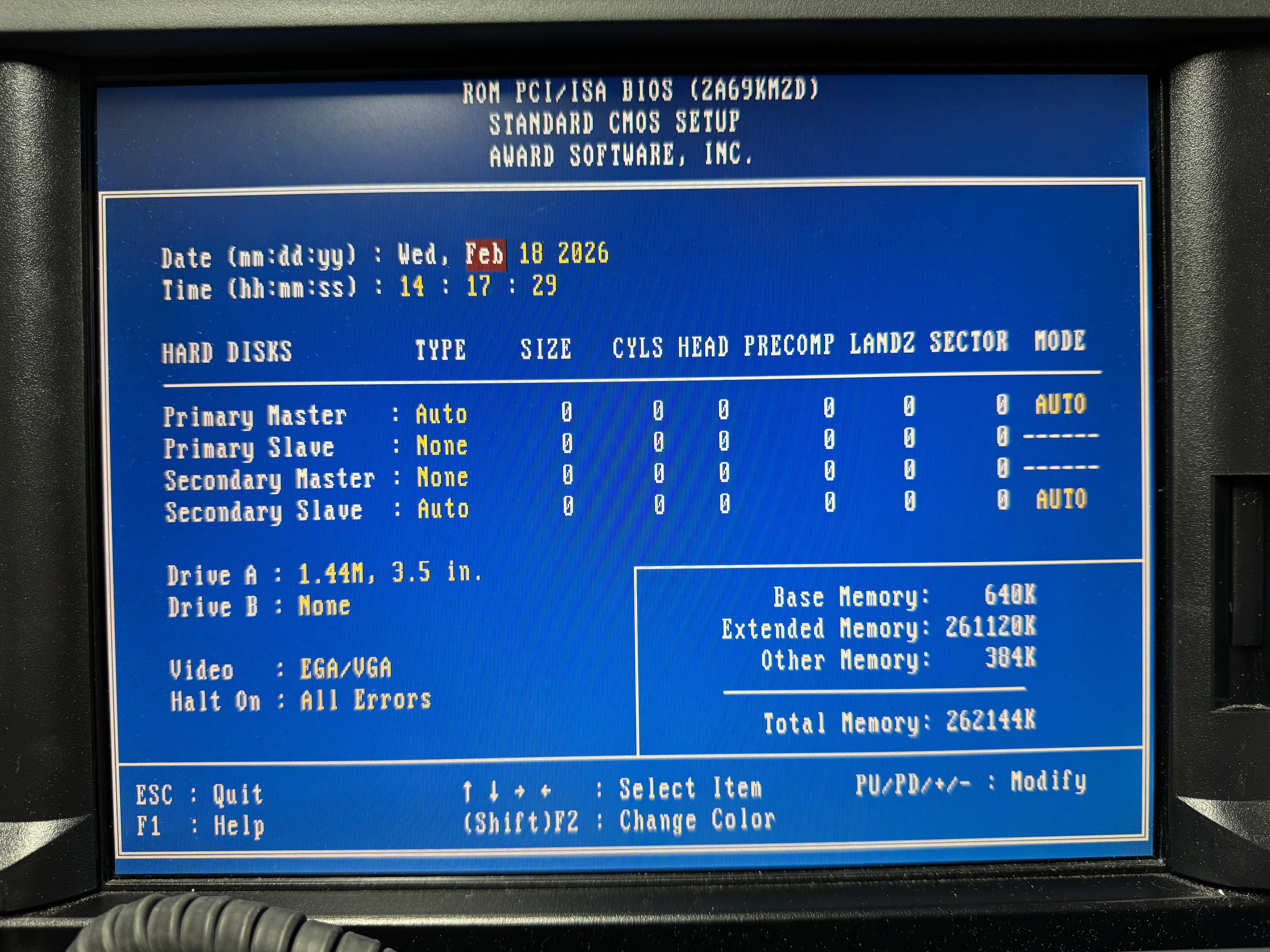
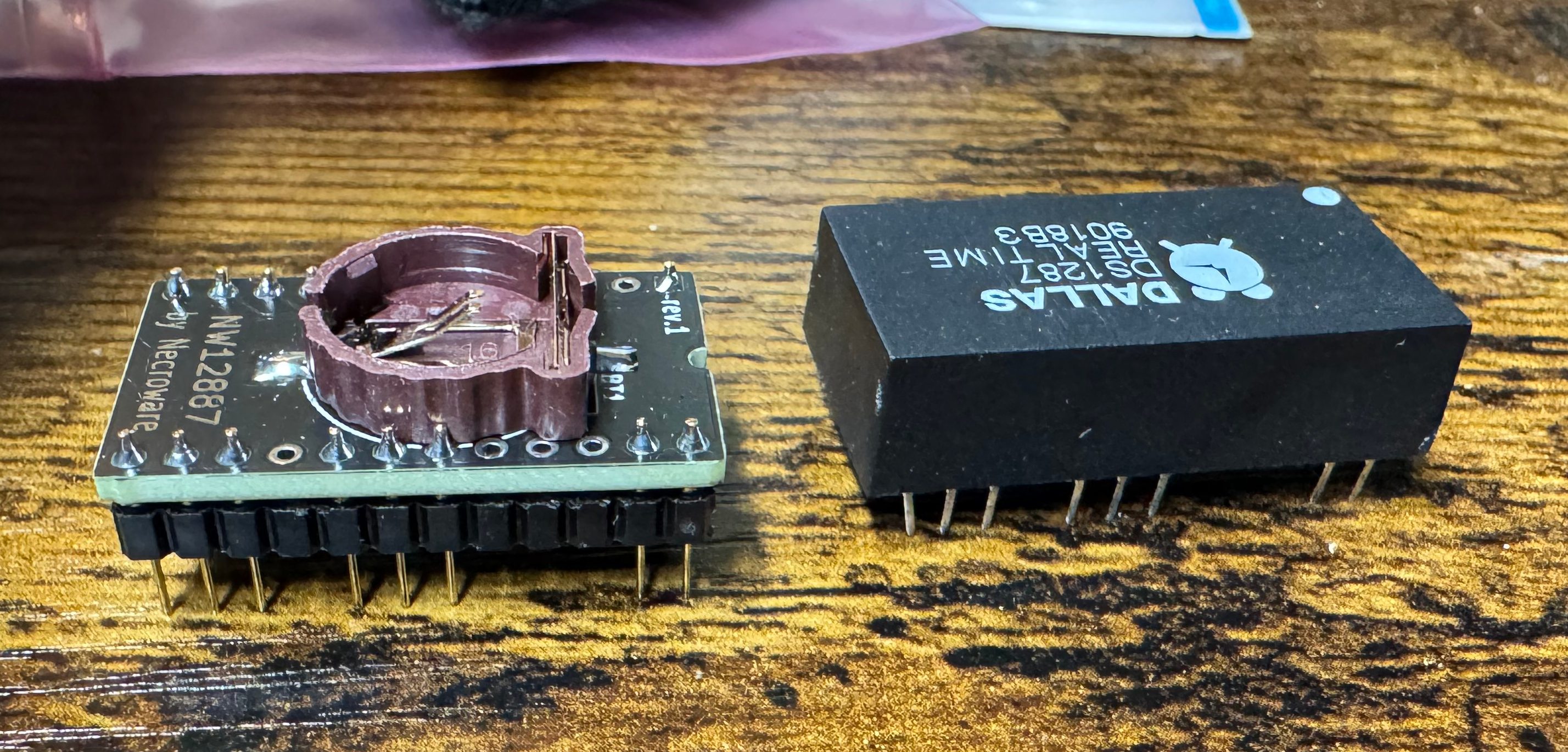
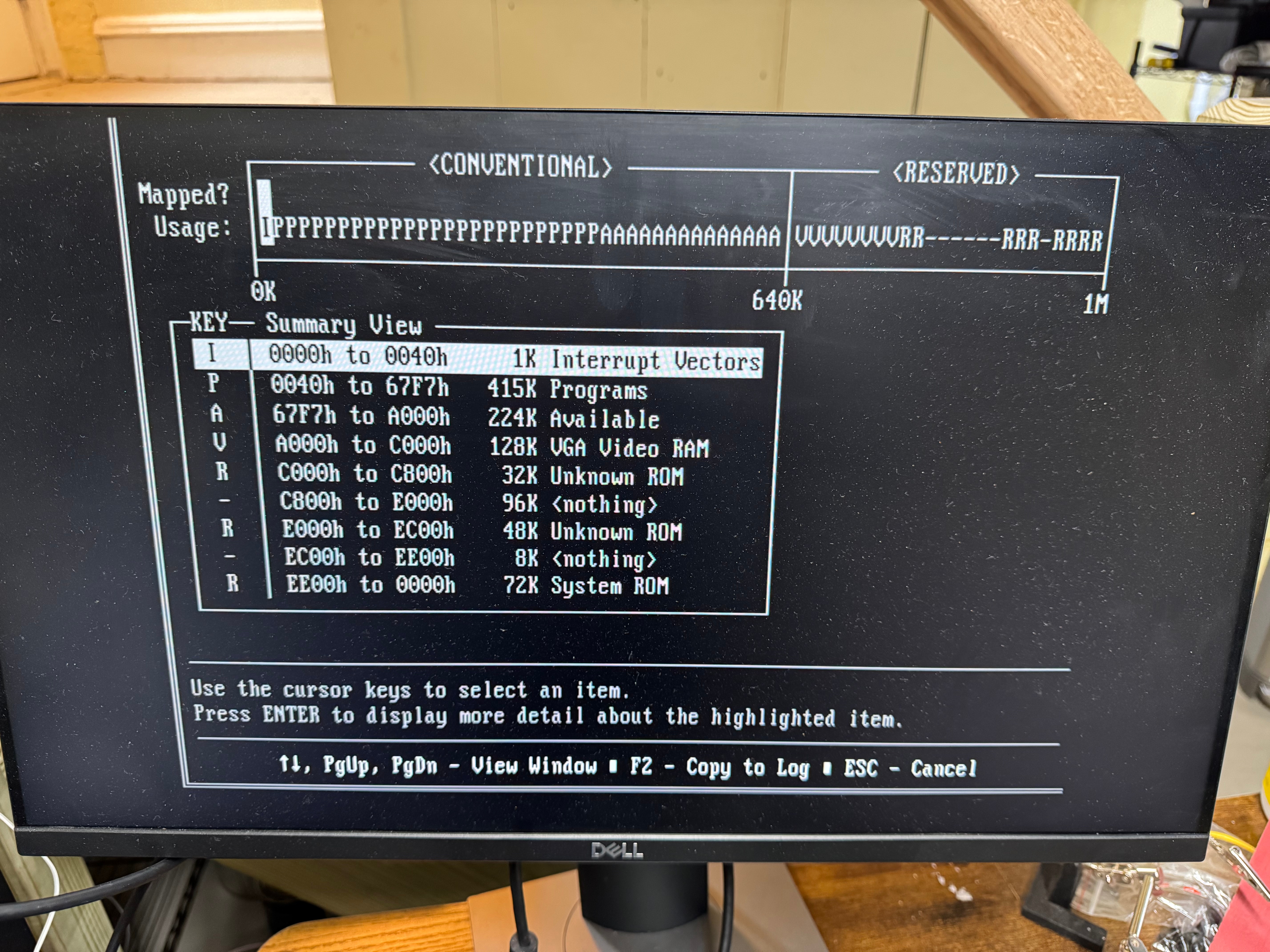
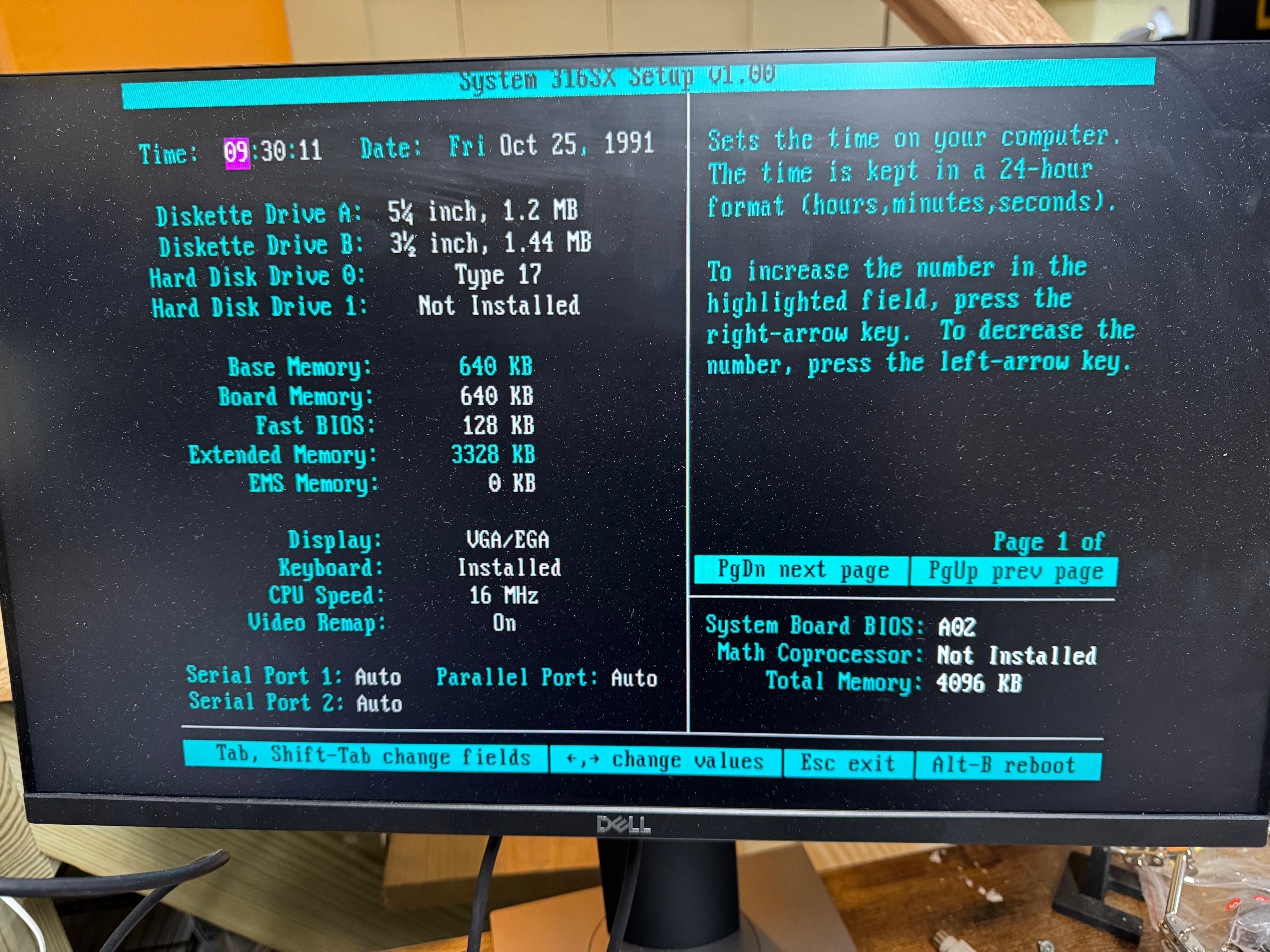
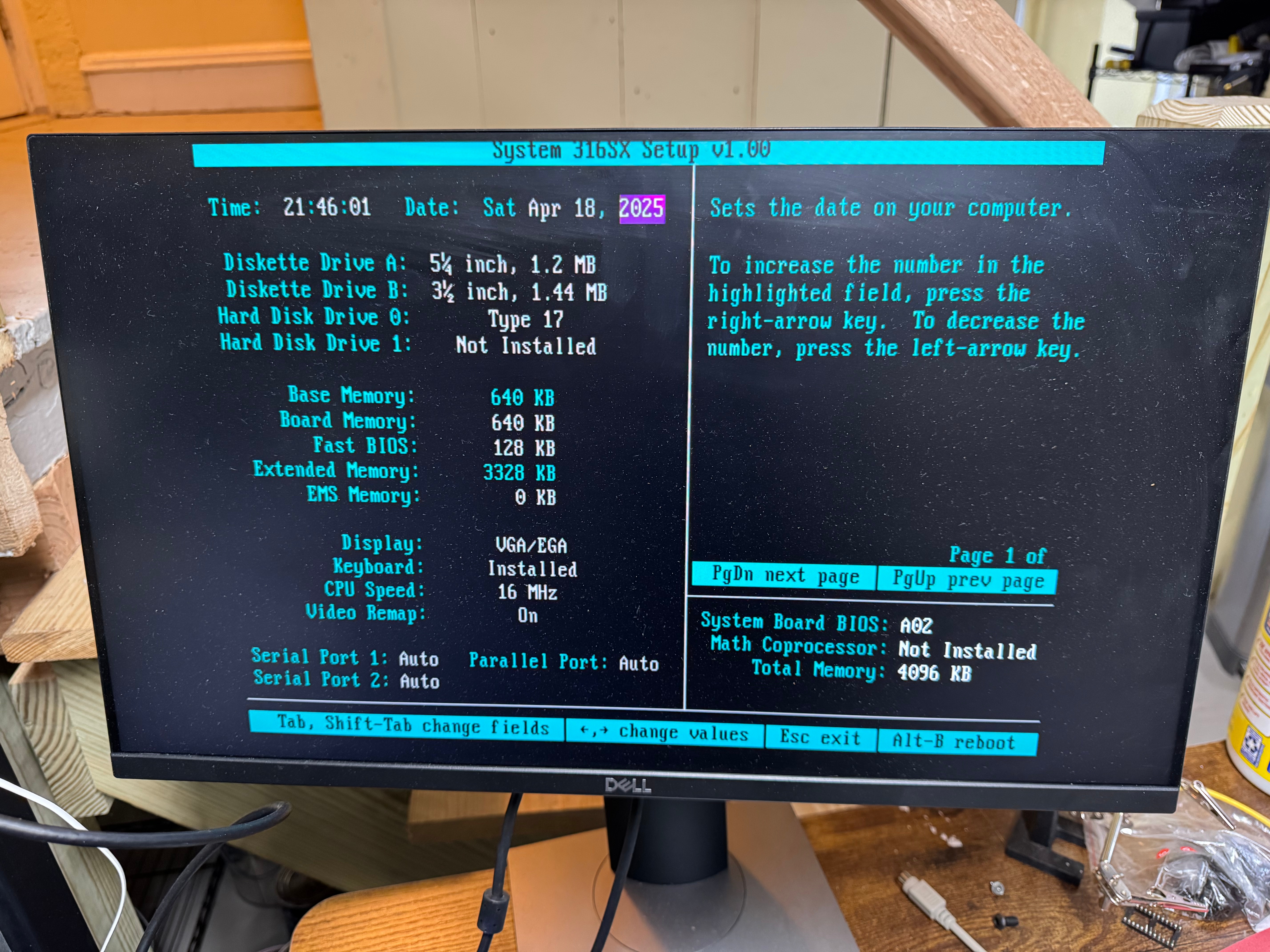
Some features gave more difficulty than others, getting the real time clock right took a while. It kept reporting the date incorrectly, but luckily that is the first thing the firmware asks you and this made it quick to iterate on.
After having a basic emulator working, I turned my sights on seeing if I could get two emulators to communicate. MAME and the web emulator didn’t support this, so it would take some additional research, but a big part of this device’s charm and soul was its ability to communicate between devices.
Again, leaning on Opus 4.6 here, Claude wrote its own disassembler to look at the ROM and how it communicated in the real device to a co-processor and then radio. My idea was to use a multicast network to simulate the radio channels, this treats your local Wi-Fi as a shared medium. This took a lot of trying. The beacons kept not being right and the devices wouldn’t show themselves to each other, but after much trying, success! The original devices have a co-processor that handles the wireless communications. The main CPU hands off comms to this other chip, which we are trying to emulate. Also wireless is half-duplex, and we are emulating that on a much faster and full duplex medium.
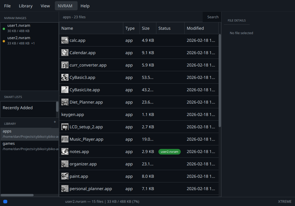
With the emulator working, I thought it would be worth putting together a manager application for all the apps I got off the Cybiko Archive. The manager allows you to load them into different NVRAM images that the emulator can then use. For the Cybiko Manager initial version I spent 10 minutes working on a mock UI and creating a design doc. Then in 24 minutes Claude Code built the whole thing… We have been iterating on the manager ever since. Some recent features include the ability for the manager to decode the icons for all the apps and display them.
In getting the code working, daberkow/cybiko-java-emulator: Cybiko Emulator and Manager written in Java, I then had Claude do a port to C. If I wanted to run the emulator on embedded devices, then I would need a C version, daberkow/cybiko-c-emulator. For that one I just targeted the Cybiko Xtreme, ditching the if statements for different versions of devices.
For anyone interested, I had Claude create new research documents as we went about, covering different parts of the emulator: https://github.com/daberkow/cybiko-java-emulator/blob/main/docs/research/wireless-protocol.md, https://github.com/daberkow/cybiko-java-emulator/blob/main/docs/research/rf2915-research.md cover different parts of the radio system for example.
Future Plans
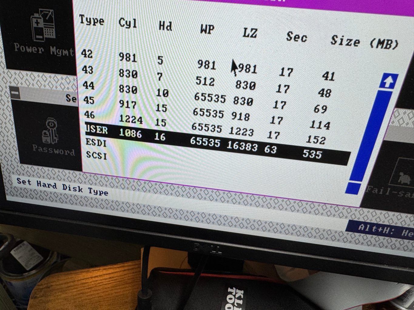
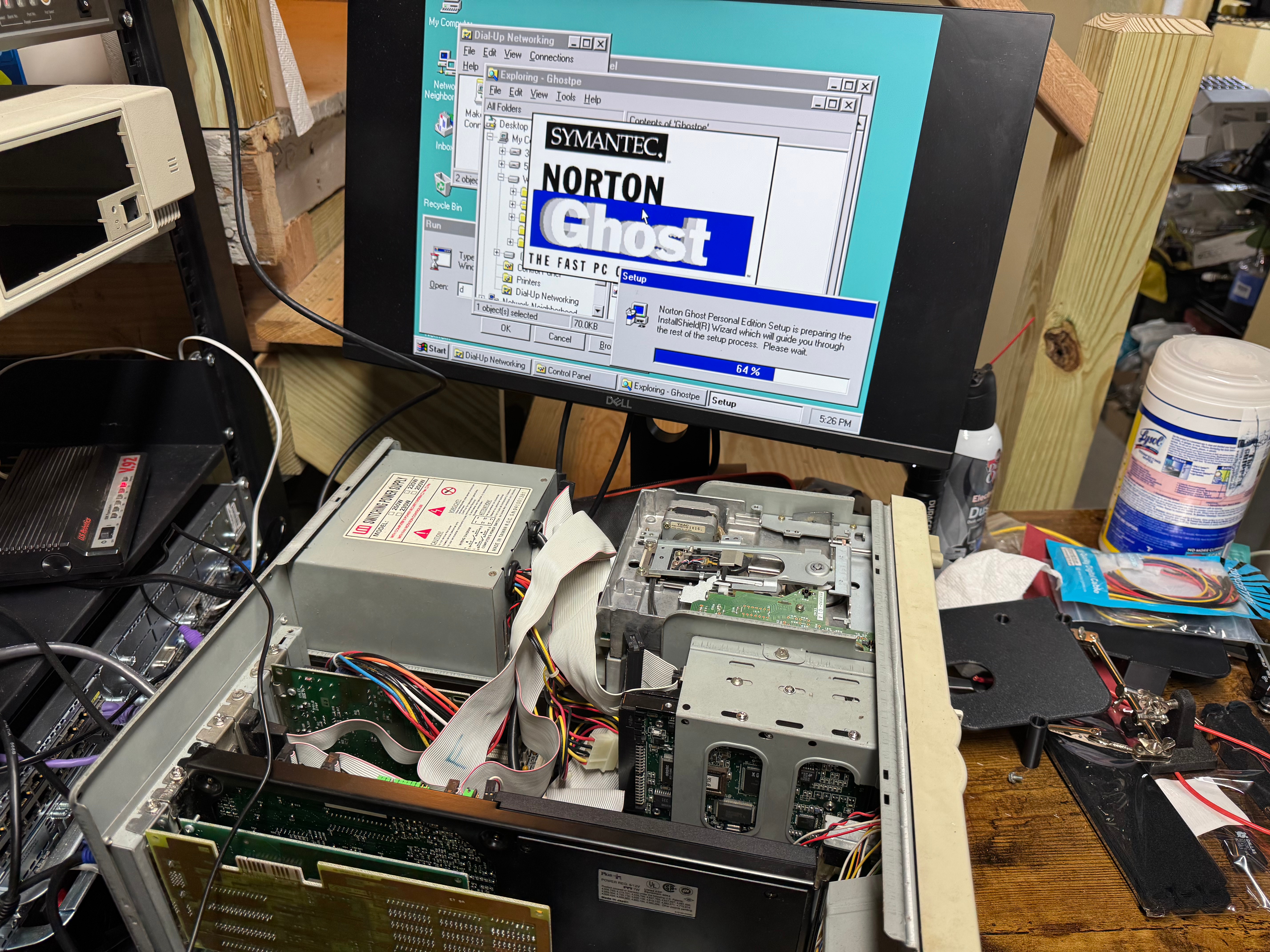
I have a long list of things I would like to eventually get working here. There are a few paths. First, real device interactions. Both via a software-defined radio to an emulator: SDR for having a modern PC talk to a Cybiko. But also using serial comms to hopefully get the manager able to push apps to devices. That way a modern computer can hook to a Cybiko and copy over games and books, maybe even act as an internet relay! The original apps were designed for Windows 9x and are not easy to get working. One difficulty is that radios are half-duplex, at any time you are either listening OR broadcasting. And with software-defined radios, they are not always the quickest to switch back and forth. I may need two, one for transmit and one for receive, which the connection code will need to handle.
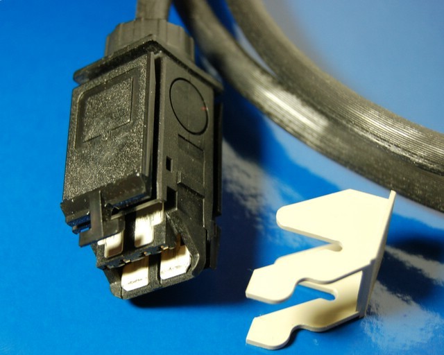
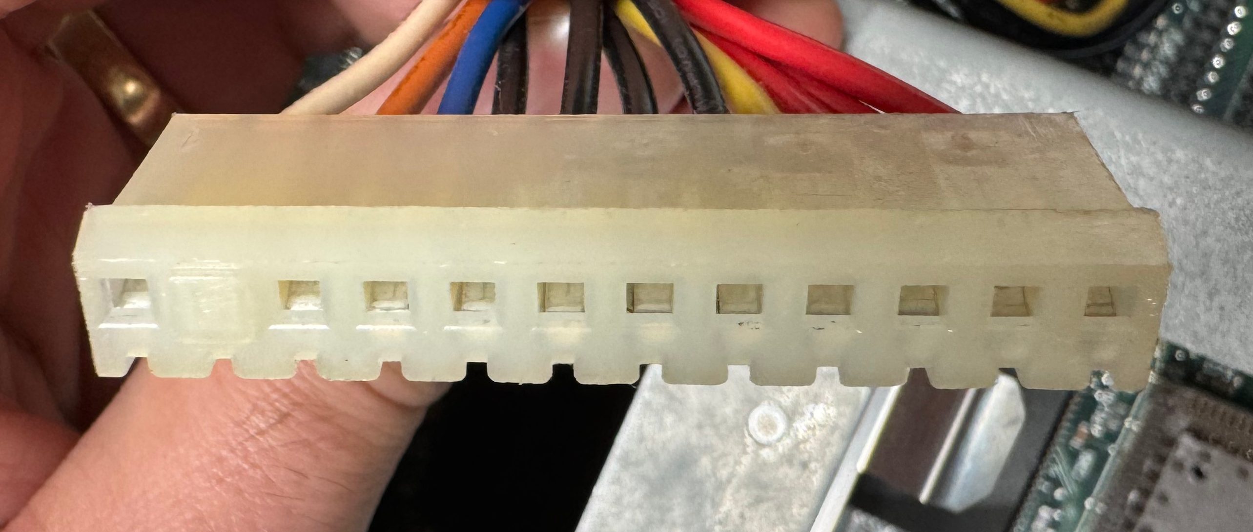
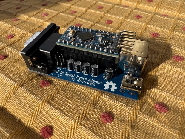
I have been working on some documents I may put up as another article about the real Cybiko V1 and its serial connection. It uses a proprietary thin serial cable. A lot of these have been lost to time, and now just the serial cable can go for $50 on eBay. I hope to find a way to recreate them easily. You can get a V1 Cybiko off eBay for $20-$30, but then you have no cable and way to send data to it.
Another path could be resurrecting some of the original tools and making it easier to program for the emulator or a real device.
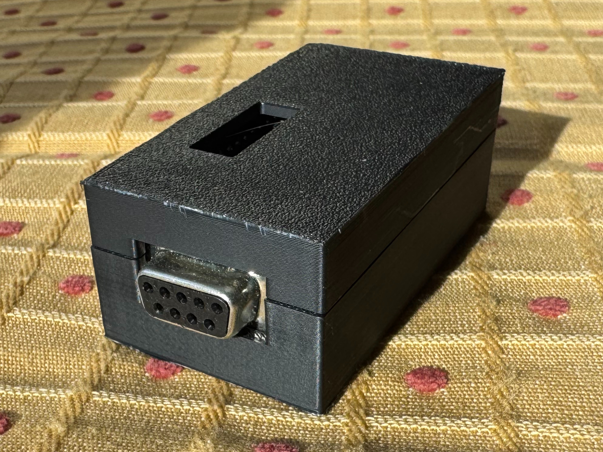
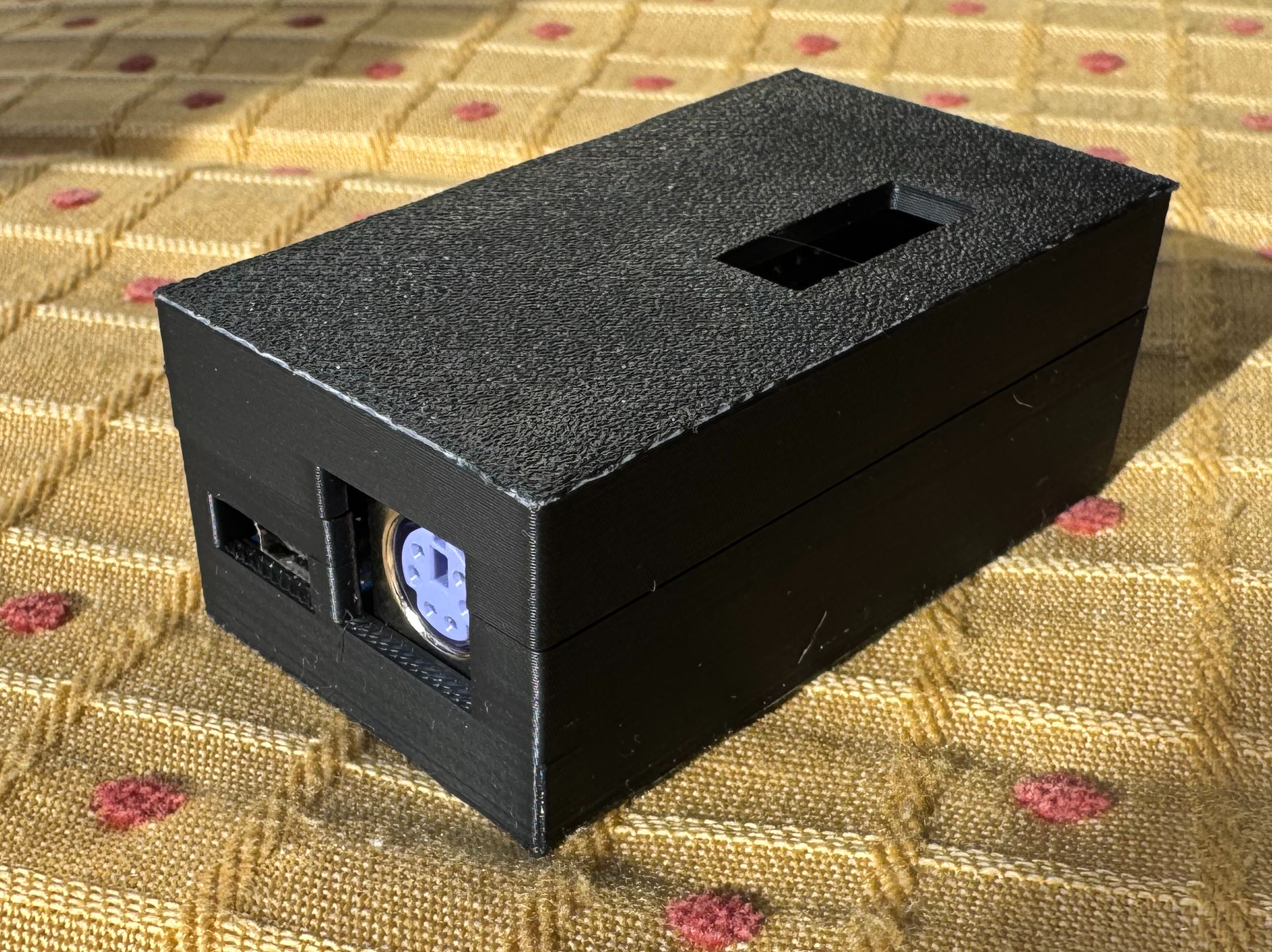
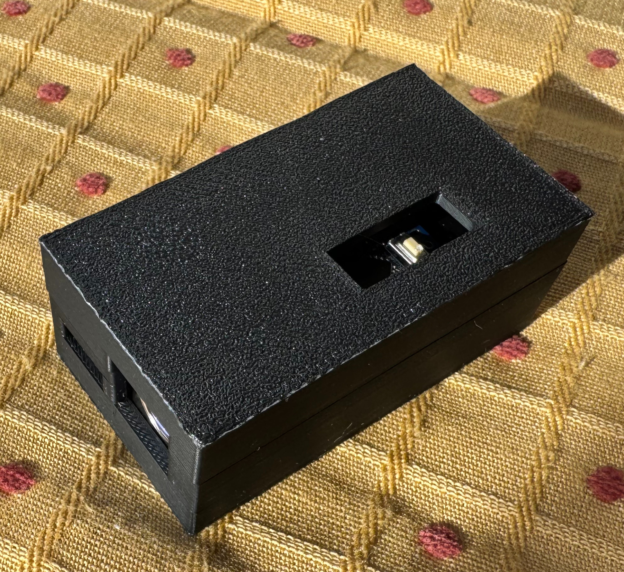
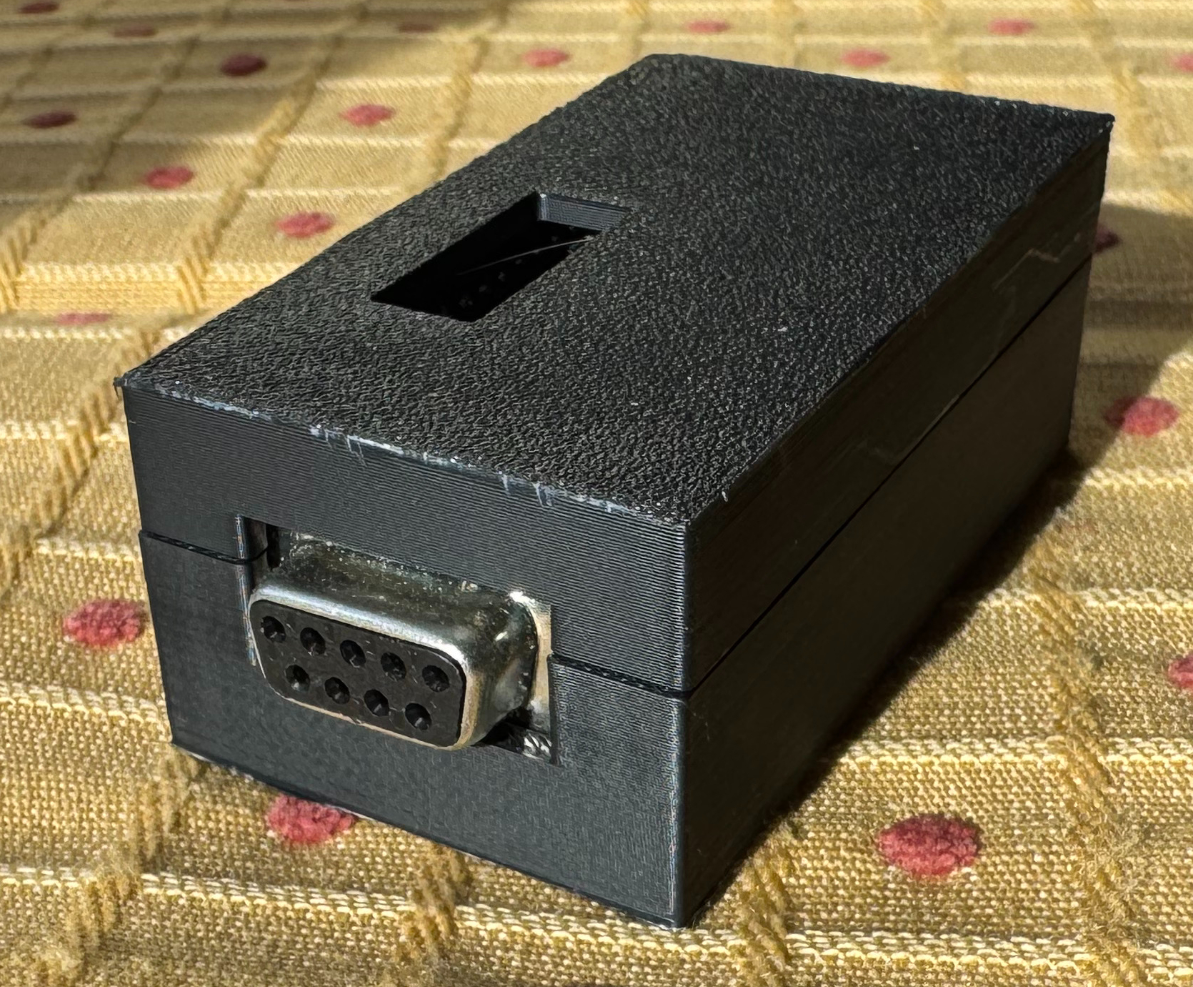
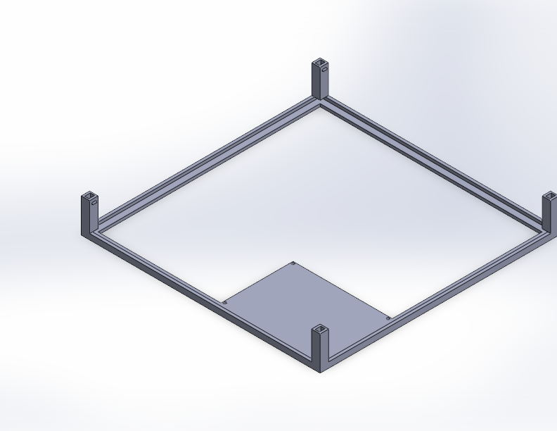
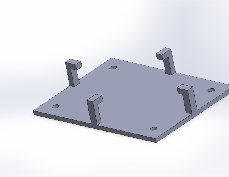
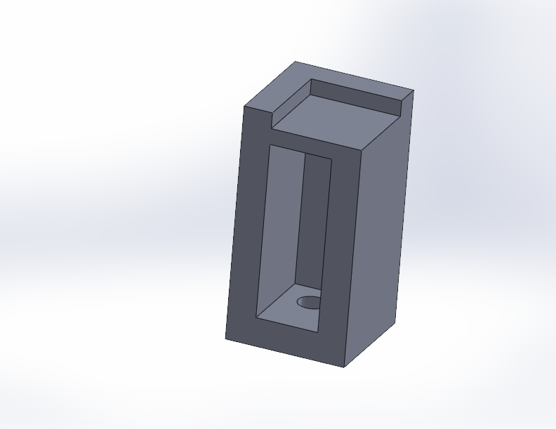
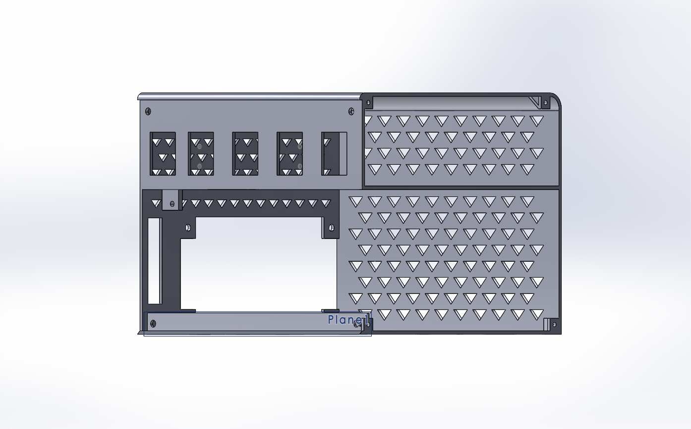
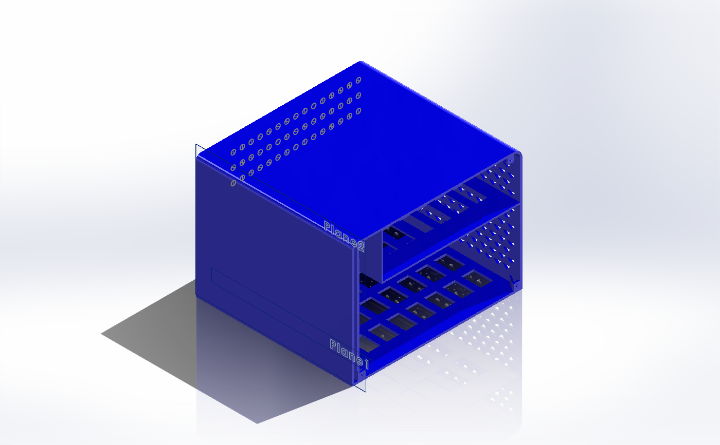
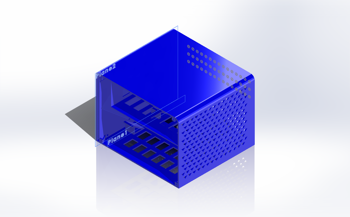
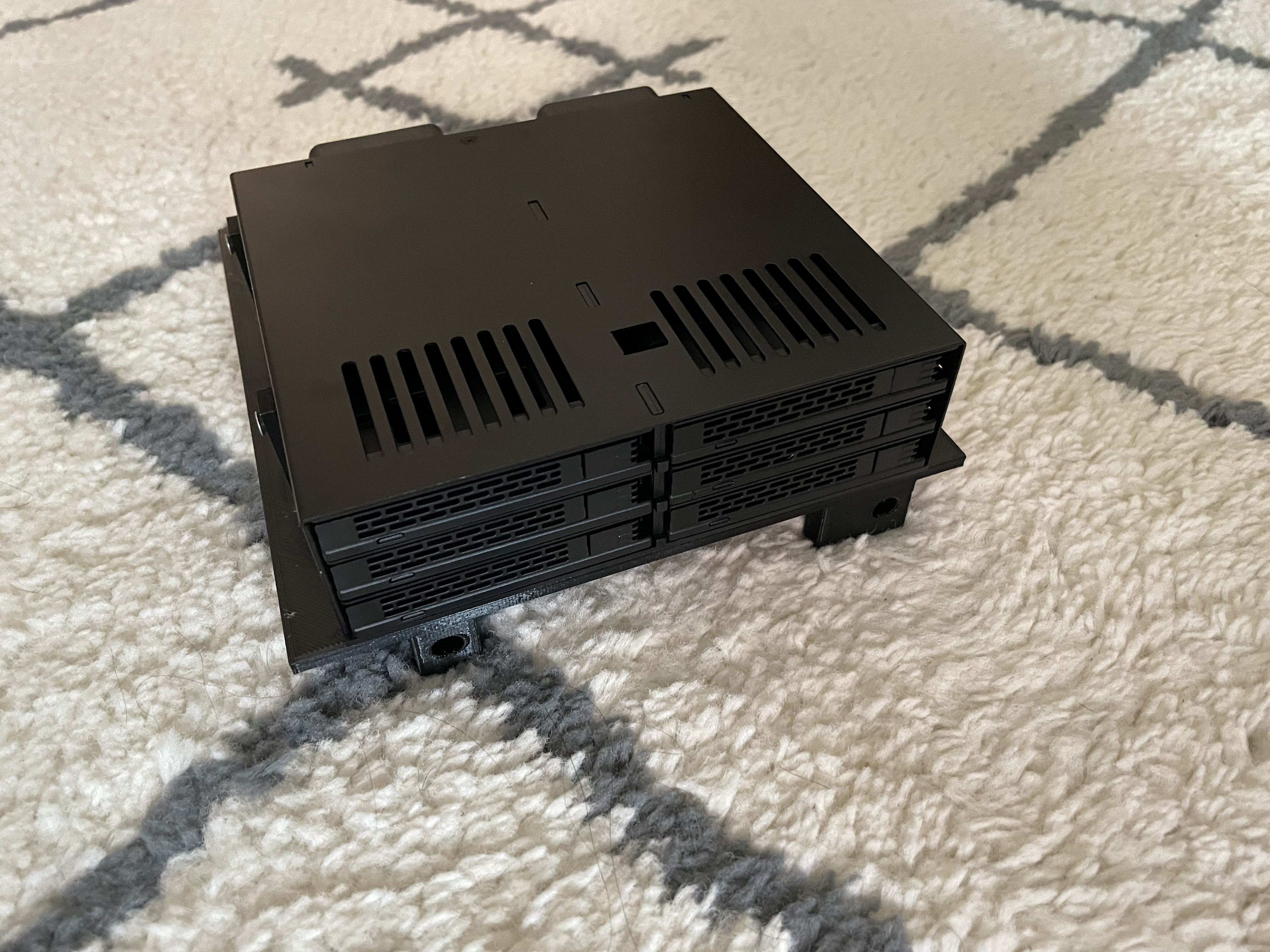
Last, my one-day moonshot is to create a little Linux device that is close to the original hardware’s size, running the emulator and an SDR to be able to simulate a real device.
This article is already long; I will post another article talking about my journey to get the emulator on the ESP32 / LilyGo T-Deck. I did get it to work, daberkow/cybiko-lilygo, but the ESP32-S3 with its limited internal RAM only managed about 10 FPS, which made it not very usable.
Right now, we have a working Java emulator that covers a good amount of the hardware and can communicate between emulators. There’s also a port of that emulator for just the Xtreme to C, and then a specific build for the LilyGo T-Deck. The Java version is the most documented, please give it a go and let me know how it works for you!
Appendix
Example of Claude Code working through a problem
● Good, the RAM dump is captured. Now let me also capture the I2C trace output. Let me run again briefly and focus on the I2C logs.● Bash(java -cp build/classes/java/main org.example.cybiko.CybikoXtreme src/main/resources/cybikoxt/cyrom150.bin src/main/resources/cybikoxt/cyos_v1508.bin --headless…) ⎿ [I2C-TRACE] PC=0x4ADE8A DR write 0x0A → SCL=HIGH [I2C-TRACE] PC=0x4A456E DDR write 0xCB → SDA=LOW [I2C] START … +56 lines (ctrl+o to expand) ⎿ (timeout 30s)● Excellent! Now I can see the full I2C sequence. Let me analyze what's happening: 1. CyOS reads all 16 RTC registers (pos 0-15) - gets correct time: sec=0x35, min=0x14, hour=0x01, day=0x99, month=0x02 2. CyOS writes ALL 16 registers back with defaults: control=0x84 (stop), time=Jan 1 00:00:00, alarm regs with some values 3. CyOS writes control=0x04 (counting enabled, mode bit set) 4. CyOS periodically reads registers 1-7 getting the Jan 1 defaults back, with seconds advancing So CyOS intentionally resets the RTC to Jan 1 every boot. Now let me disassemble the actual CyOS code to understand why. The I2C code is around PC=0x4A4500. Let me extract and disassemble it from the RAM dump.● Read 1 file (ctrl+o to expand)● Now let me write a simple H8S disassembler and analyze the I2C code region. The I2C bit-bang code is at PC 0x4A4500-0x4A4700. In the RAM dump, external RAM starts at 0x400000, so that's offset 0xA4500.● Task(H8S disassembler for CyOS I2C) ⎿ Backgrounded agent (shift+↑ to manage · ctrl+o to expand)● While the disassembler is being built, let me examine the raw bytes around the I2C code directly. The I2C bit-bang routines are at PC 0x4A4500-0x4A4700, which is RAM offset 0xA4500.● Bash(xxd -s 0xA4500 -l 0x300 /tmp/cyos_ram.bin | head -60) ⎿ 000a4500: 1b00 1770 1a91 8918 5e4b 4838 6e4a 0003 ...p....^KH8nJ.. 000a4510: f200 1772 0aa0 1a91 893c 5e4b 4838 6e4a ...r.....<^KH8nJ 000a4520: 0004 f200 1772 0aa0 1a91 893c 5e4b 4838 .....r.....<^KH8 … +35 lines (ctrl+o to expand)
Bash(javac -cp build/classes/java/main /tmp/V2Debug30.java -d /tmp && java -cp build/classes/java/main:/tmp V2Debug30 2>/dev/null) ⎿ Loaded boot ROM: src/main/resources/cybikoxt/cyrom117.bin (32768 bytes) Loaded flash ROM: src/main/resources/cybikoxt/cyos_v1358.bin (262144 bytes) Loaded SPI dataflash: src/main/resources/cybikoxt/flash_v1358.bin (540672 bytes) … +58 lines (ctrl+o to expand)● VRAM never changes after boot ROM - CyOS never writes to the LCD. Serial output stops at "Checking cartridge..." and the string "Initializing extern file devices" exists in RAM but never gets printed. Let me find what happens after the cartridge check.● Searched for 1 pattern (ctrl+o to expand)● Good - I can see the init sequence in the ROM. After "Checking cartridge..." (at offset 0x403c) the next messages should be "Initializing standard file devices" (0x417f), then "Initializing .tors..." (0x41a4), then "Initializing extern file devices" (0x41e3). None get printed. Let me find the code that references the "Checking cartridge" string.● Read 3 files (ctrl+o to expand)● The strings aren't loaded via simple MOV.L #imm. Let me trace the actual function call chain during the critical transition from scan completion to idle state.
 Critical discovery! The reschedule() function at 0x1068E4 CALLS 0x106ABC with the current task. And prepare_task() at 0x106874 copies base_priority (offset +85) to current_priority (offset +84) and inserts the task into the
   ready_queue at 0x200230. The context switch compares ready task vs current task priorities.

  The key question: what's the base_priority of the timer entry tasks? And does the context switch actually happen? Let me create a targeted debug.