Projects

Writing a Cybiko Emulator

Background

I have always loved devices. Growing up, my parents would have a Blackberry or before that Palm Pilot, and I thought they were amazing. Seeing my interest, my parents got me a Cybiko Xtreme. A PDA designed for teens and college kids. With games, books, apps, and even wireless communications, all of this in 2001! The device and company have an interesting history:

To quote Rameriez in 2002 (https://everything2.com/title/Cybiko):

With Yang’s surname, the made in Taiwan sticker on the back, and Japanese name (Cybiko means Cyber-Girl in Japanese), you’d be forgiven for mistaking this as an asian product. But, the Cybiko was designed, programmed and tested in Russia.

“They don’t exactly hide the fact that Cybiko’s Russian, but let’s say, they don’t highlight it either.”

(Vaidyanathan Sivakumar, Fund Manager)

There were three iterations of the Cybiko. V1, V2, and Xtreme. The V1 and V2 look very similar. V2 saved some money by cutting the RAM in half. The Xtreme had a whole different look and upgraded the memory and CPU. All of them had a radio operating at ~900 MHz. Some features were really ahead of their time with wireless chat and being able to have one device act as a base station giving other devices E-Mail, or WAP web browsing. You could download E-Mail over serial for V1/V2 and mini-USB for Xtreme to later manually sync back. All of this for around $100 in 2001 or $185 today. There was also an MP3 player add-on for the devices, allowing earlier MP3 usage.

I had an Xtreme with the MP3 player add-on. Being able to play music, games, and go on primitive WAP web pages in 2001 was awesome. There was also a client for AOL Instant Messenger. I could sit in bed and chat with friends from school. In the era of the giant family desktops in the living room, this was a big upgrade!

Goal

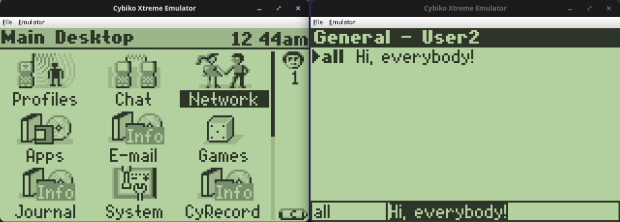
Having one of the devices from my childhood and wanting to play around with it more, I found that MAME has an emulator for it created by Tim Schuerewegen around 2001-2007. He did a fantastic job keeping the device alive for people. He’s also active in the Cybiko Discord and wrote a newer web version that I encourage anyone wanting to play around with it to try!
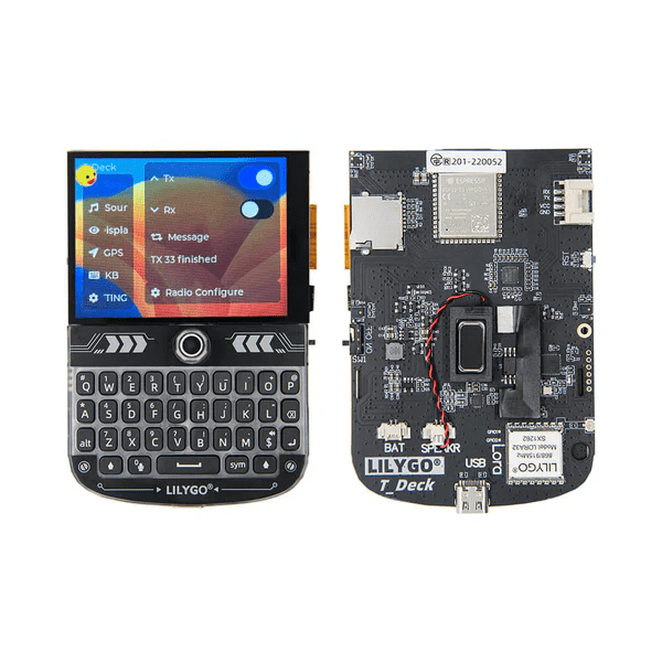
I have been playing with the ESP32, and then found the LilyGo T-Deck, I wanted to see if I could port an emulator onto the device and how close to a full Cybiko it could be. That started me down a path of researching the MAME code and seeing if I could extract enough out for a functioning emulator.

Planning

MAME is an amazing system with many layers to its backend. It has many different CPUs, screens, chipsets emulated, and you can create a new device connecting these different pieces. The issue is that all of that is overhead and on our tiny ESP32, I knew I would need to strip it down as far as I could, and at that point I was basically making a new emulator. I’m also not the best at C, and figured if I was going to make a new emulator I would want to start in Java, then if/when there were issues, I could much more easily diagnose them. There is the downside that Java is slower than some other languages. The Cybiko Xtreme ran at 18 MHz and with its slow black and white screen I figured it would be ok for now. I ended up adding some code where the console outputs how close to real time the frame was delivered, and on my old laptop, frames were ready well before they were needed.

And that is where this project stalled for a while. Creating a new emulator is a giant task, and I didn’t have the time to spend, which I guessed would be weeks, if not months. Enter Claude Code… I figured I would give it a try, and with MAME as its reference, see if we could get the emulator going.

I kept research notes here: https://github.com/daberkow/cybiko-java-emulator/tree/main/docs/research on many parts of the Cybiko system.

Development

This was my first example of how quickly Claude Code works; the original emulator took 10 hours to get Cybiko Xtreme working… then I had too much faith and didn’t save and Claude broke the emulator trying to add a feature and we had 7 hours of fixing (too much trust). That’s when I learned to frequently commit changes to git as things started working. After getting back up and running (and committing code) it took 2 hours to add original Cybiko V1 support. I tried to add V2 but it handled the OS image differently and something was weird. After 12 hours of trying Claude gave up. We later went back and gave it another go and got V2 working. I created a roadmap of features to add sound, try to get communications working, real hardware connection via SDR!

Some features gave more difficulty than others, getting the real time clock right took a while. It kept reporting the date incorrectly, but luckily that is the first thing the firmware asks you and this made it quick to iterate on.

After having a basic emulator working, I turned my sights on seeing if I could get two emulators to communicate. MAME and the web emulator didn’t support this, so it would take some additional research, but a big part of this device’s charm and soul was its ability to communicate between devices.

Again, leaning on Opus 4.6 here, Claude wrote its own disassembler to look at the ROM and how it communicated in the real device to a co-processor and then radio. My idea was to use a multicast network to simulate the radio channels, this treats your local Wi-Fi as a shared medium. This took a lot of trying. The beacons kept not being right and the devices wouldn’t show themselves to each other, but after much trying, success! The original devices have a co-processor that handles the wireless communications. The main CPU hands off comms to this other chip, which we are trying to emulate. Also wireless is half-duplex, and we are emulating that on a much faster and full duplex medium.

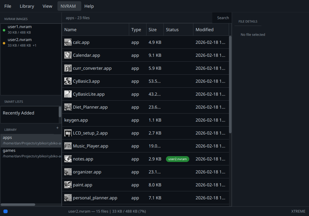
With the emulator working, I thought it would be worth putting together a manager application for all the apps I got off the Cybiko Archive. The manager allows you to load them into different NVRAM images that the emulator can then use. For the Cybiko Manager initial version I spent 10 minutes working on a mock UI and creating a design doc. Then in 24 minutes Claude Code built the whole thing… We have been iterating on the manager ever since. Some recent features include the ability for the manager to decode the icons for all the apps and display them.
In getting the code working, daberkow/cybiko-java-emulator: Cybiko Emulator and Manager written in Java, I then had Claude do a port to C. If I wanted to run the emulator on embedded devices, then I would need a C version, daberkow/cybiko-c-emulator. For that one I just targeted the Cybiko Xtreme, ditching the if statements for different versions of devices.

For anyone interested, I had Claude create new research documents as we went about, covering different parts of the emulator: https://github.com/daberkow/cybiko-java-emulator/blob/main/docs/research/wireless-protocol.md, https://github.com/daberkow/cybiko-java-emulator/blob/main/docs/research/rf2915-research.md cover different parts of the radio system for example.

Future Plans

I have a long list of things I would like to eventually get working here. There are a few paths. First, real device interactions. Both via a software-defined radio to an emulator: SDR for having a modern PC talk to a Cybiko. But also using serial comms to hopefully get the manager able to push apps to devices. That way a modern computer can hook to a Cybiko and copy over games and books, maybe even act as an internet relay! The original apps were designed for Windows 9x and are not easy to get working. One difficulty is that radios are half-duplex, at any time you are either listening OR broadcasting. And with software-defined radios, they are not always the quickest to switch back and forth. I may need two, one for transmit and one for receive, which the connection code will need to handle.

I have been working on some documents I may put up as another article about the real Cybiko V1 and its serial connection. It uses a proprietary thin serial cable. A lot of these have been lost to time, and now just the serial cable can go for $50 on eBay. I hope to find a way to recreate them easily. You can get a V1 Cybiko off eBay for $20-$30, but then you have no cable and way to send data to it.

Another path could be resurrecting some of the original tools and making it easier to program for the emulator or a real device.

Last, my one-day moonshot is to create a little Linux device that is close to the original hardware’s size, running the emulator and an SDR to be able to simulate a real device.

This article is already long; I will post another article talking about my journey to get the emulator on the ESP32 / LilyGo T-Deck. I did get it to work, daberkow/cybiko-lilygo, but the ESP32-S3 with its limited internal RAM only managed about 10 FPS, which made it not very usable.

Right now, we have a working Java emulator that covers a good amount of the hardware and can communicate between emulators. There’s also a port of that emulator for just the Xtreme to C, and then a specific build for the LilyGo T-Deck. The Java version is the most documented, please give it a go and let me know how it works for you!

Appendix

Example of Claude Code working through a problem

● Good, the RAM dump is captured. Now let me also capture the I2C trace output. Let me run again briefly and focus on the I2C logs.
● Bash(java -cp build/classes/java/main org.example.cybiko.CybikoXtreme src/main/resources/cybikoxt/cyrom150.bin src/main/resources/cybikoxt/cyos_v1508.bin --headless…)
⎿  [I2C-TRACE] PC=0x4ADE8A DR write 0x0A → SCL=HIGH
[I2C-TRACE] PC=0x4A456E DDR write 0xCB → SDA=LOW
[I2C] START
… +56 lines (ctrl+o to expand)
⎿  (timeout 30s)
● Excellent! Now I can see the full I2C sequence. Let me analyze what's happening:
1. CyOS reads all 16 RTC registers (pos 0-15) - gets correct time: sec=0x35, min=0x14, hour=0x01, day=0x99, month=0x02
2. CyOS writes ALL 16 registers back with defaults: control=0x84 (stop), time=Jan 1 00:00:00, alarm regs with some values
3. CyOS writes control=0x04 (counting enabled, mode bit set)
4. CyOS periodically reads registers 1-7 getting the Jan 1 defaults back, with seconds advancing
So CyOS intentionally resets the RTC to Jan 1 every boot. Now let me disassemble the actual CyOS code to understand why. The I2C code is around PC=0x4A4500. Let me extract and disassemble it from the RAM dump.
● Read 1 file (ctrl+o to expand)
● Now let me write a simple H8S disassembler and analyze the I2C code region. The I2C bit-bang code is at PC 0x4A4500-0x4A4700. In the RAM dump, external RAM starts at 0x400000, so that's offset 0xA4500.
● Task(H8S disassembler for CyOS I2C)
⎿  Backgrounded agent (shift+↑ to manage · ctrl+o to expand)
● While the disassembler is being built, let me examine the raw bytes around the I2C code directly. The I2C bit-bang routines are at PC 0x4A4500-0x4A4700, which is RAM offset 0xA4500.
● Bash(xxd -s 0xA4500 -l 0x300 /tmp/cyos_ram.bin | head -60)
⎿  000a4500: 1b00 1770 1a91 8918 5e4b 4838 6e4a 0003 ...p....^KH8nJ..
000a4510: f200 1772 0aa0 1a91 893c 5e4b 4838 6e4a ...r.....<^KH8nJ
000a4520: 0004 f200 1772 0aa0 1a91 893c 5e4b 4838 .....r.....<^KH8
… +35 lines (ctrl+o to expand)
Bash(javac -cp build/classes/java/main /tmp/V2Debug30.java -d /tmp && java -cp build/classes/java/main:/tmp V2Debug30 2>/dev/null)
⎿  Loaded boot ROM: src/main/resources/cybikoxt/cyrom117.bin (32768 bytes)
Loaded flash ROM: src/main/resources/cybikoxt/cyos_v1358.bin (262144 bytes)
Loaded SPI dataflash: src/main/resources/cybikoxt/flash_v1358.bin (540672 bytes)
… +58 lines (ctrl+o to expand)
● VRAM never changes after boot ROM - CyOS never writes to the LCD. Serial output stops at "Checking cartridge..." and the string "Initializing extern file devices" exists in RAM but never gets printed. Let me find what
happens after the cartridge check.
● Searched for 1 pattern (ctrl+o to expand)
● Good - I can see the init sequence in the ROM. After "Checking cartridge..." (at offset 0x403c) the next messages should be "Initializing standard file devices" (0x417f), then "Initializing .tors..." (0x41a4), then
"Initializing extern file devices" (0x41e3). None get printed. Let me find the code that references the "Checking cartridge" string.
● Read 3 files (ctrl+o to expand)
● The strings aren't loaded via simple MOV.L #imm. Let me trace the actual function call chain during the critical transition from scan completion to idle state.
 Critical discovery! The reschedule() function at 0x1068E4 CALLS 0x106ABC with the current task. And prepare_task() at 0x106874 copies base_priority (offset +85) to current_priority (offset +84) and inserts the task into the
   ready_queue at 0x200230. The context switch compares ready task vs current task priorities.

  The key question: what's the base_priority of the timer entry tasks? And does the context switch actually happen? Let me create a targeted debug.
Restoring a Dolch Pac 65: The Last of the Luggables

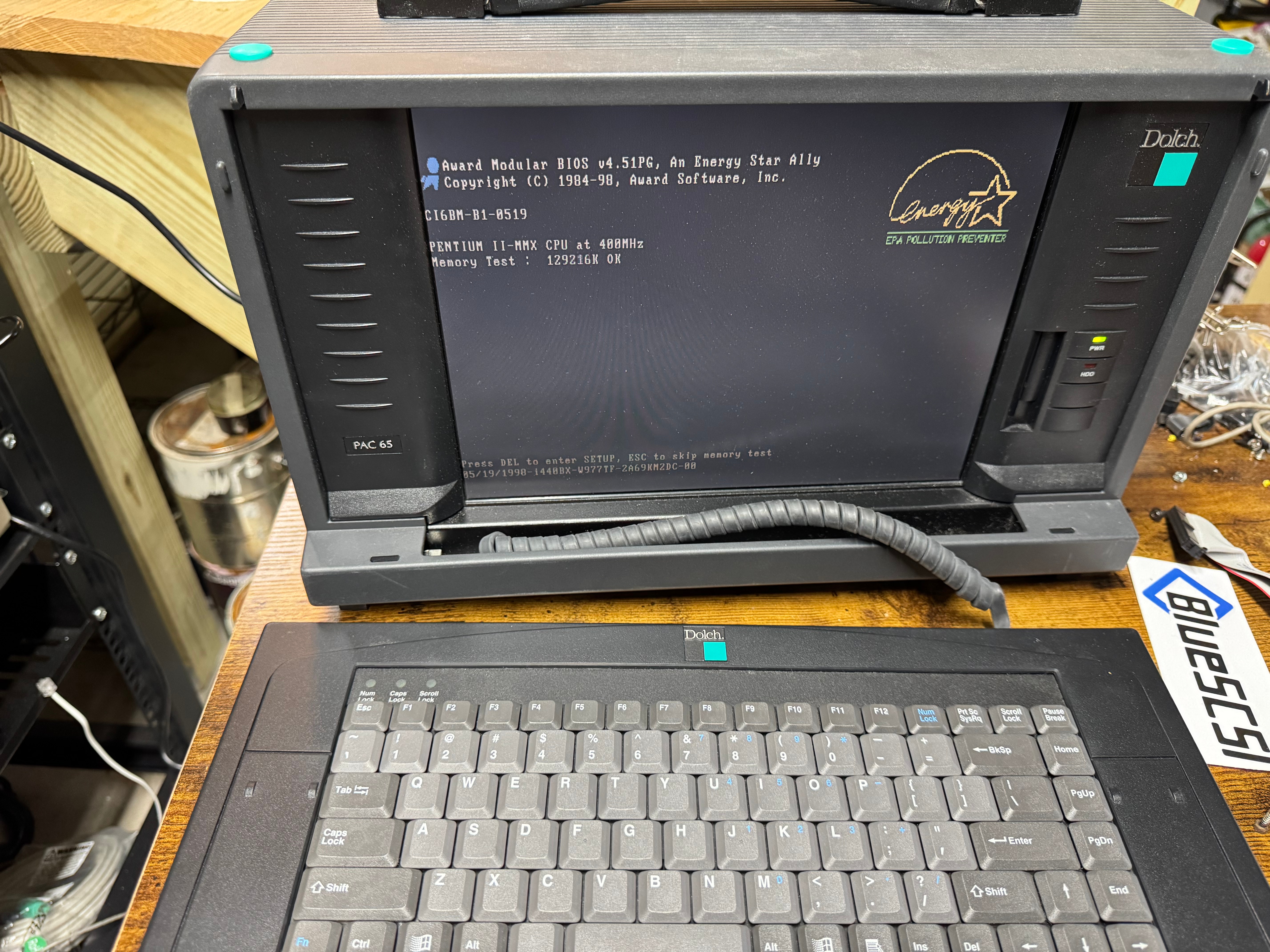
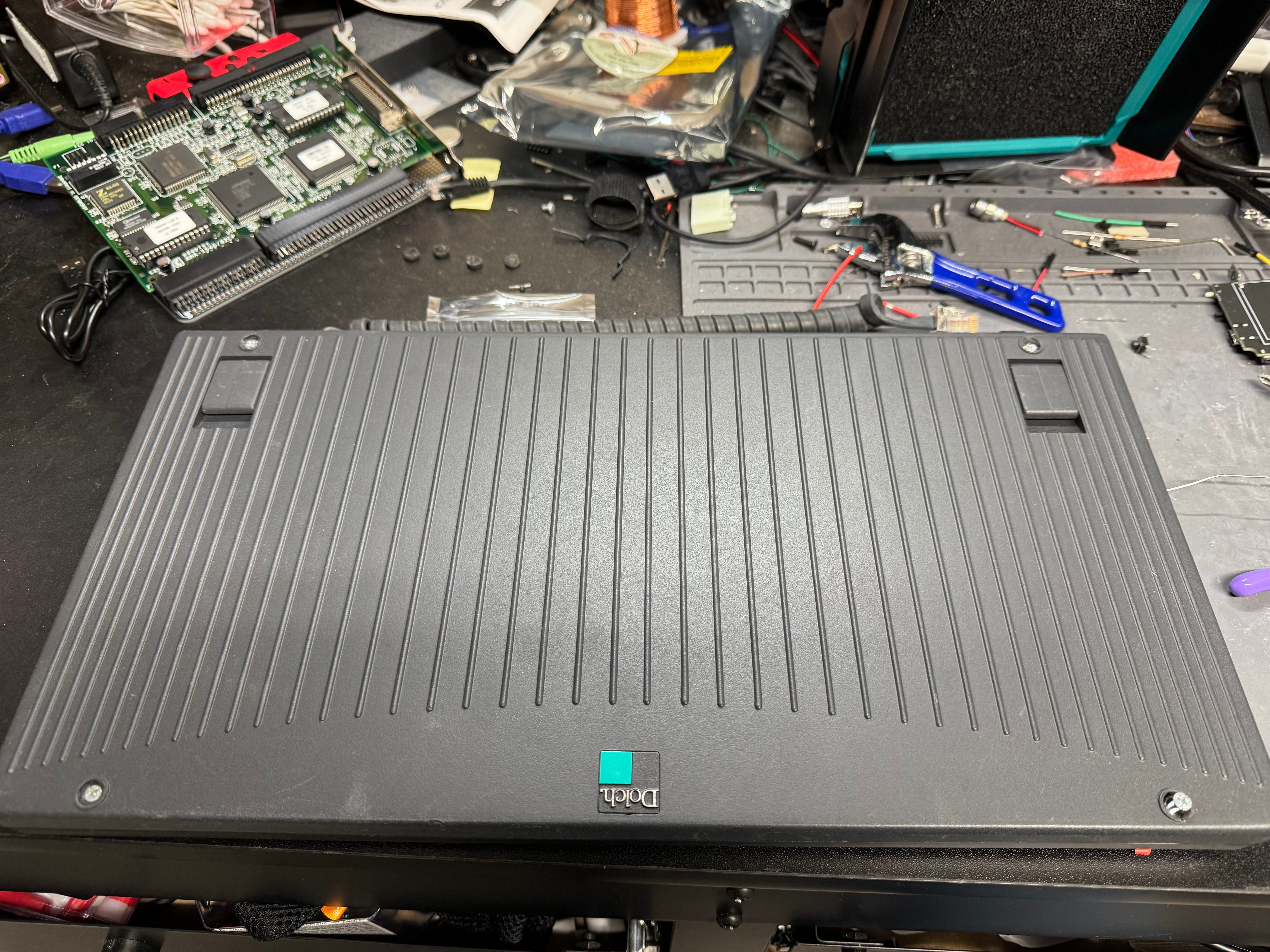
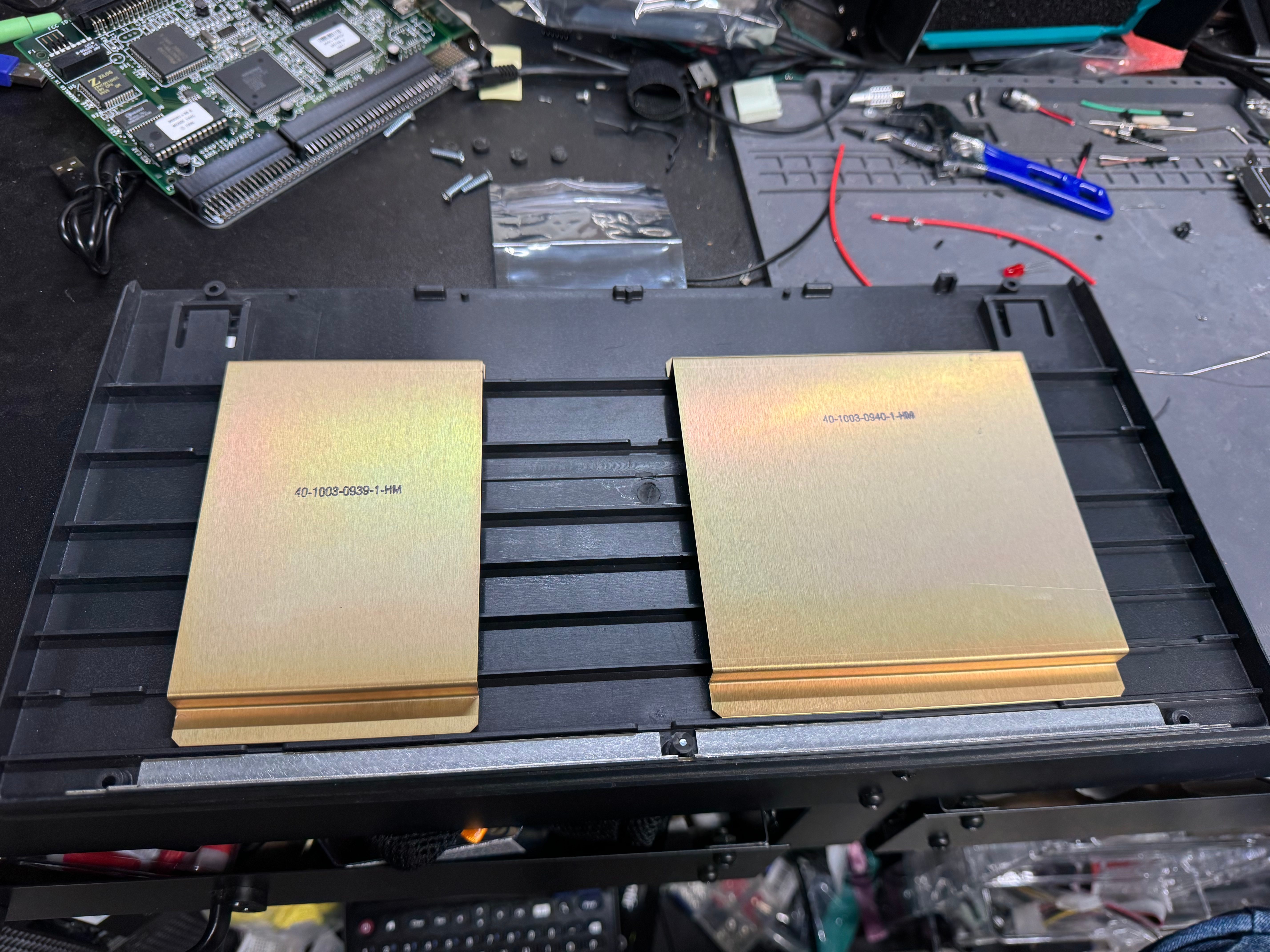
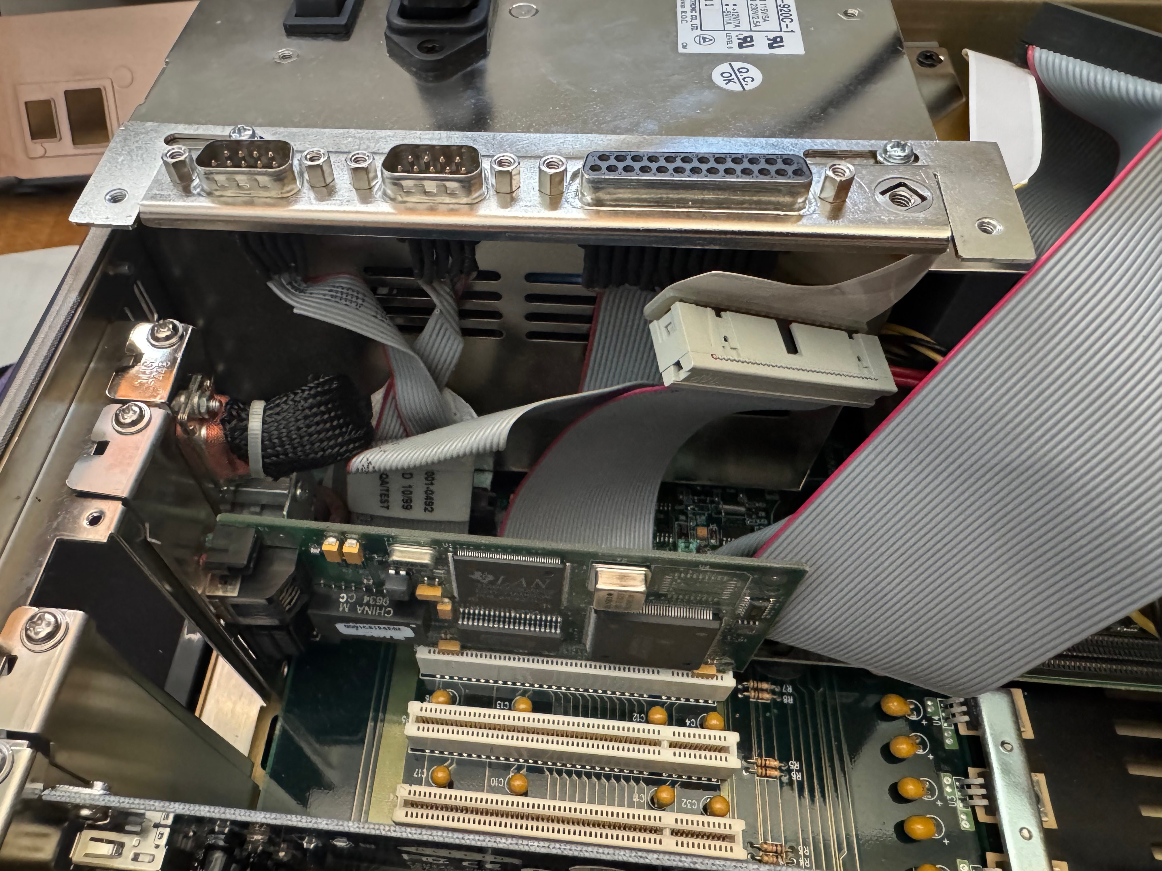
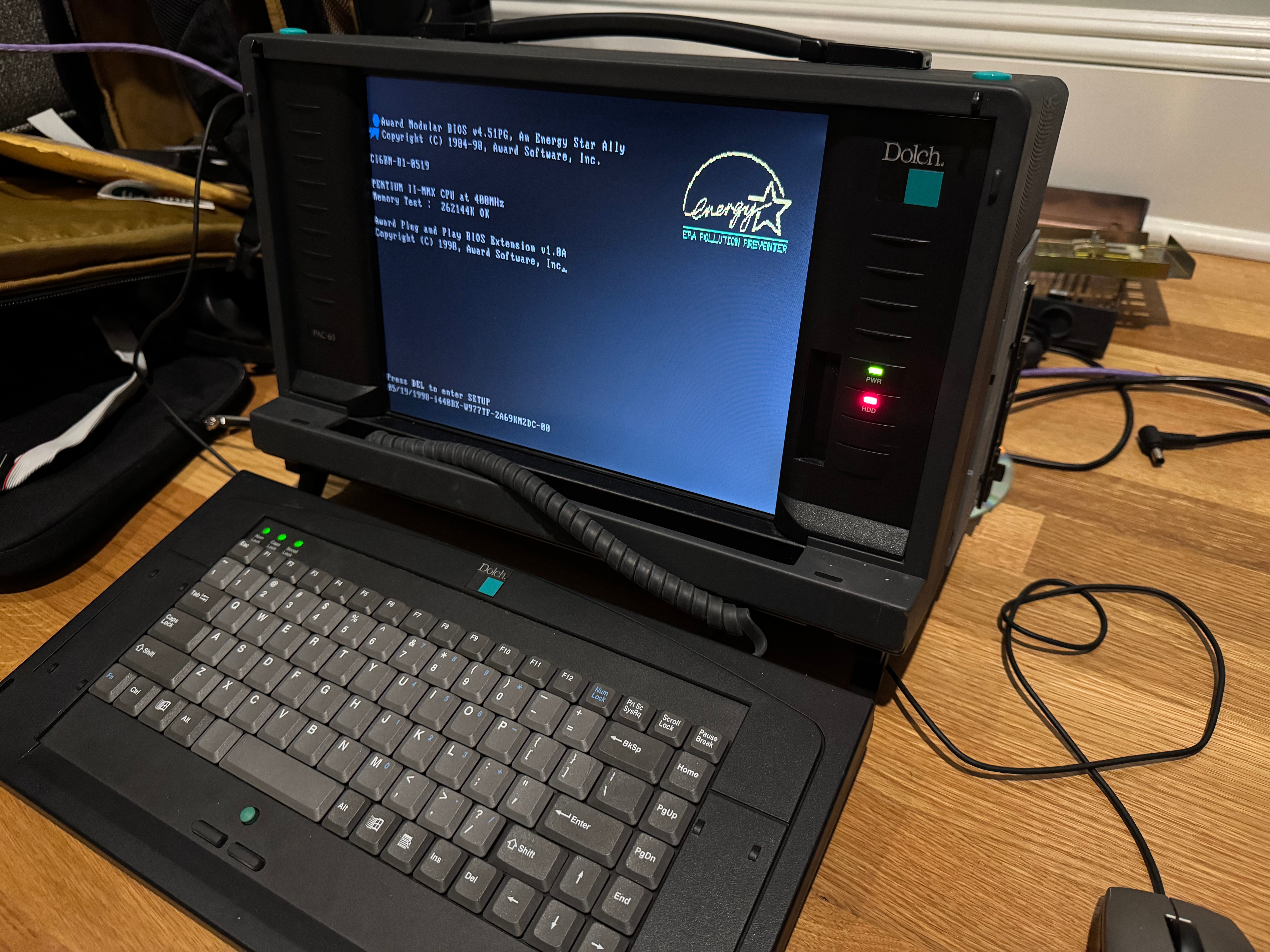
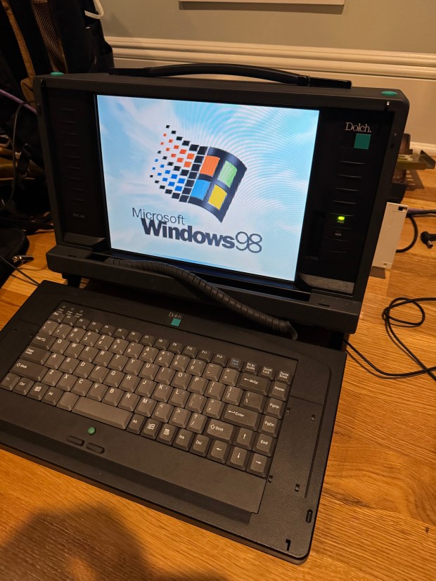
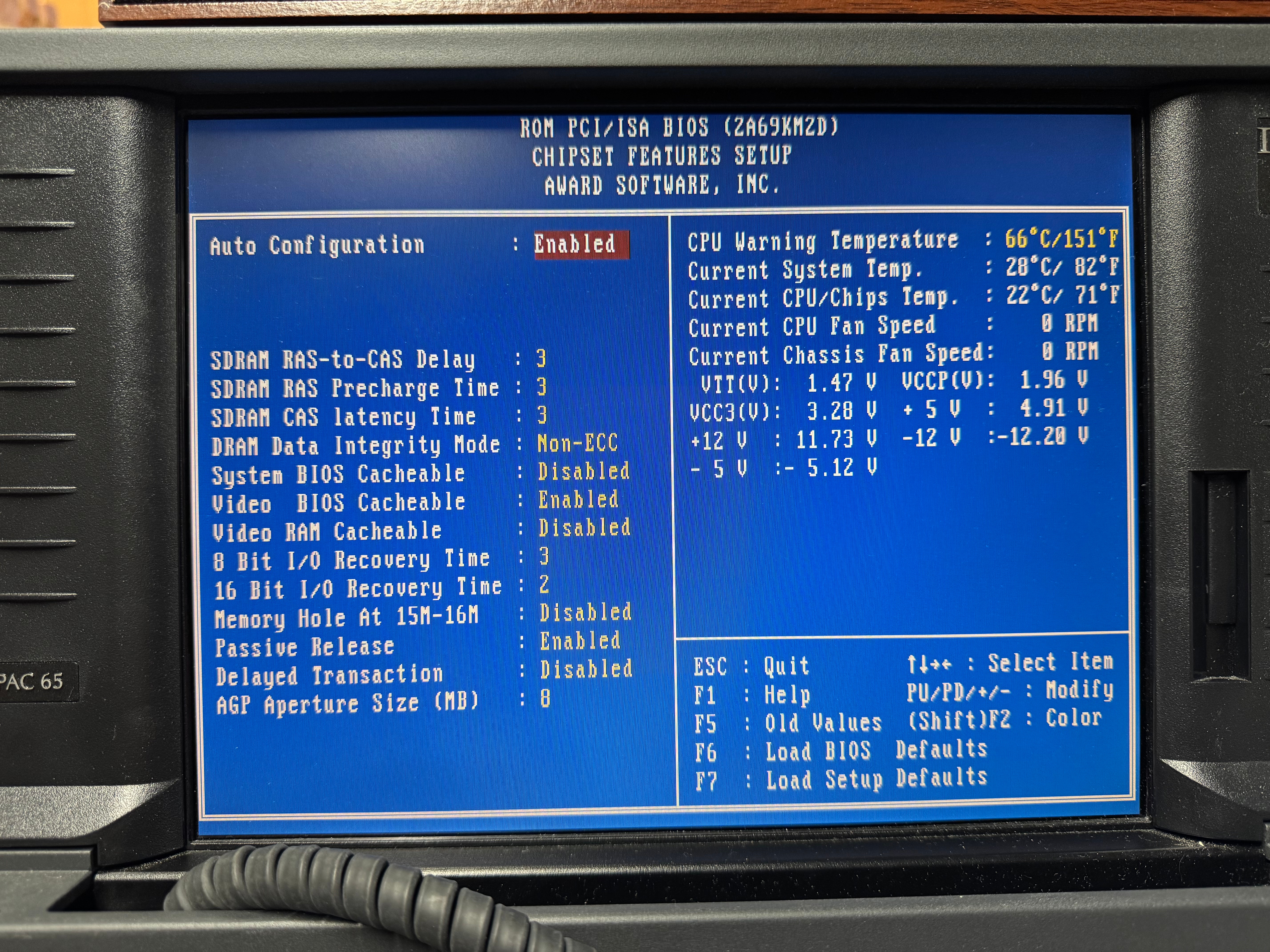
I love old portable computers. It goes back to the Compaq Portable II I have. I saw online there was a much later system from a company I hadn’t heard of called Dolch. The Dolch Pac 65, considered one of the last “luggable” computers. An industrial motherboard, with an ISA slot, four PCI slots, and a Pentium II 400MHz with MMX. These machines were built to be “portable workstations” for industrial use: factory floors, military, network diagnostics. A far cry from the Intel 286 in the Compaq Portable II. It also has an LCD screen instead of the small CRT of the Compaq. Gone are the days of tiny green and black displays, even if I love them. In comes a full 1024×768 LCD. I have been expanding my retro computing rack and wanted something more in the Windows 95 or 98 era. This system fit the bill.

Whenever I tried to find one online, they would come up for around $500. I saw one come up for around $150, with the small catch that it was in an “unknown” state and missing some of the panels and mounting brackets. I could see from one side photo that it had the power supply, and I saw what looked like the motherboard inside. A yolo later (and a few days), I had the system.

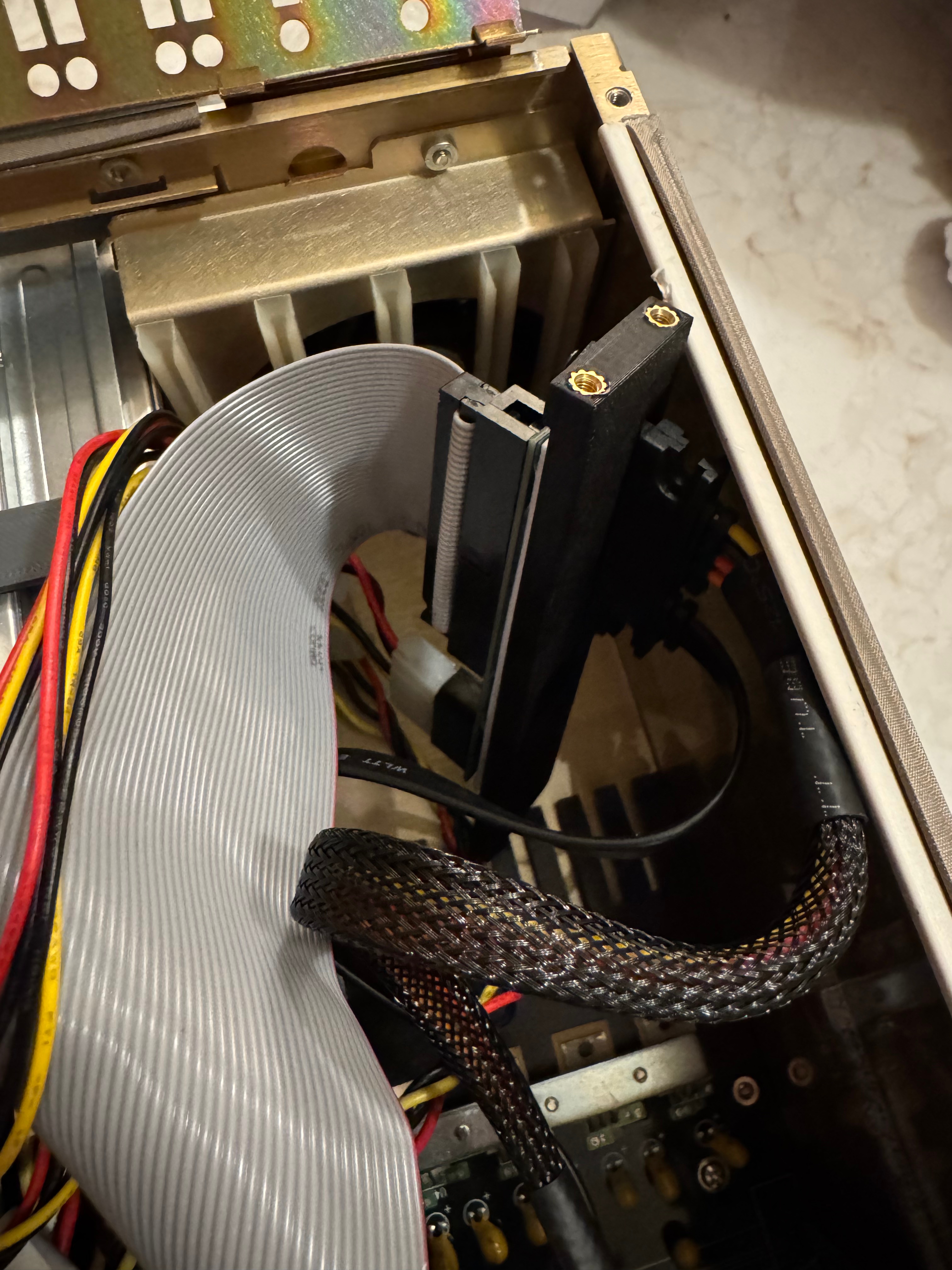
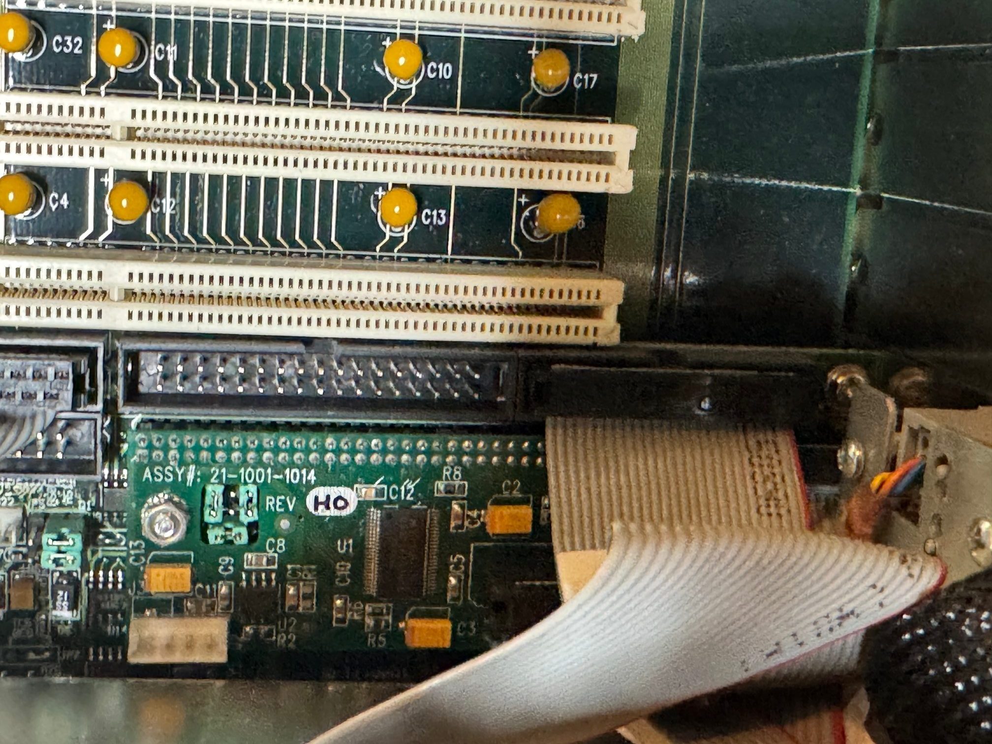
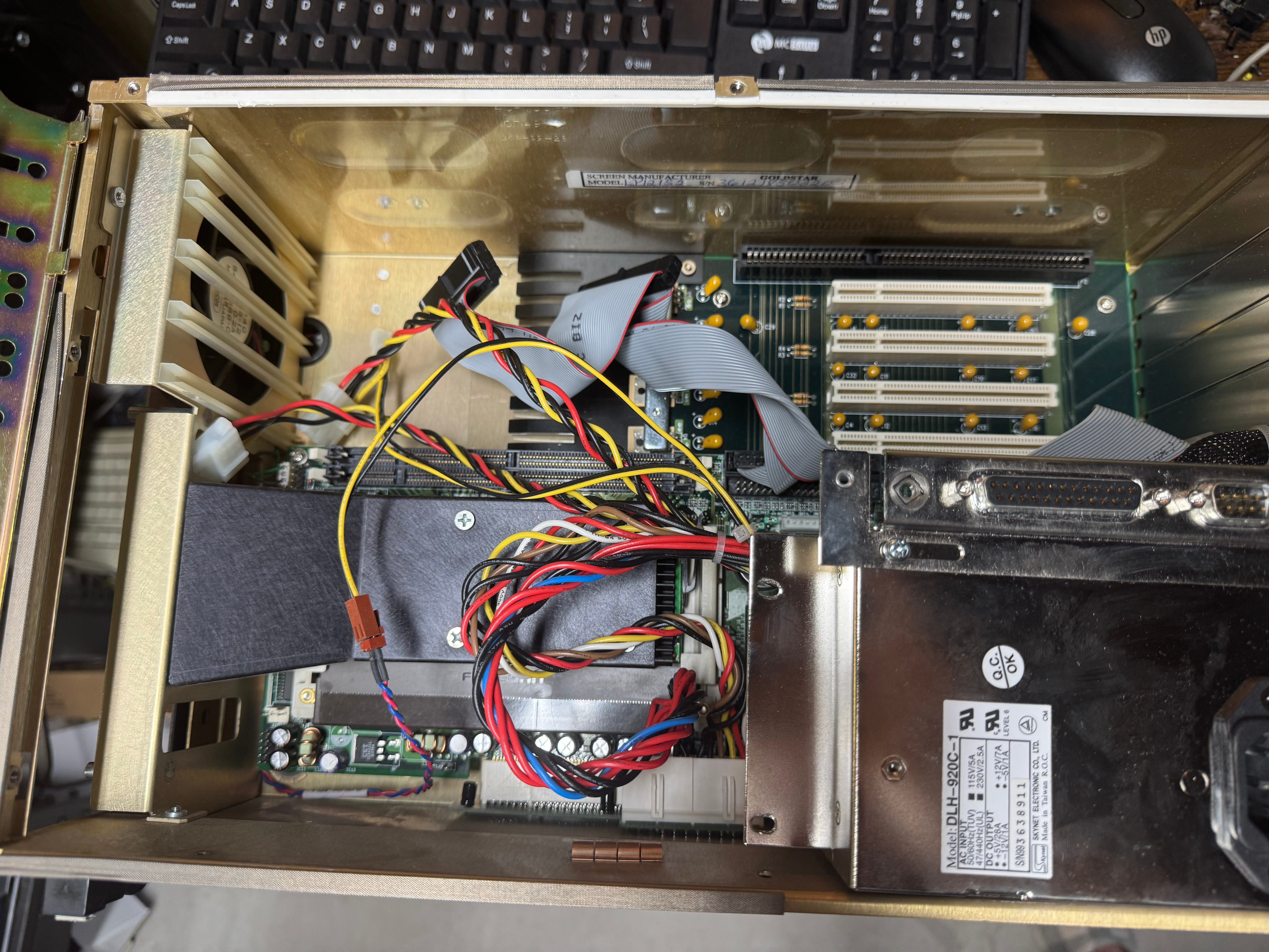
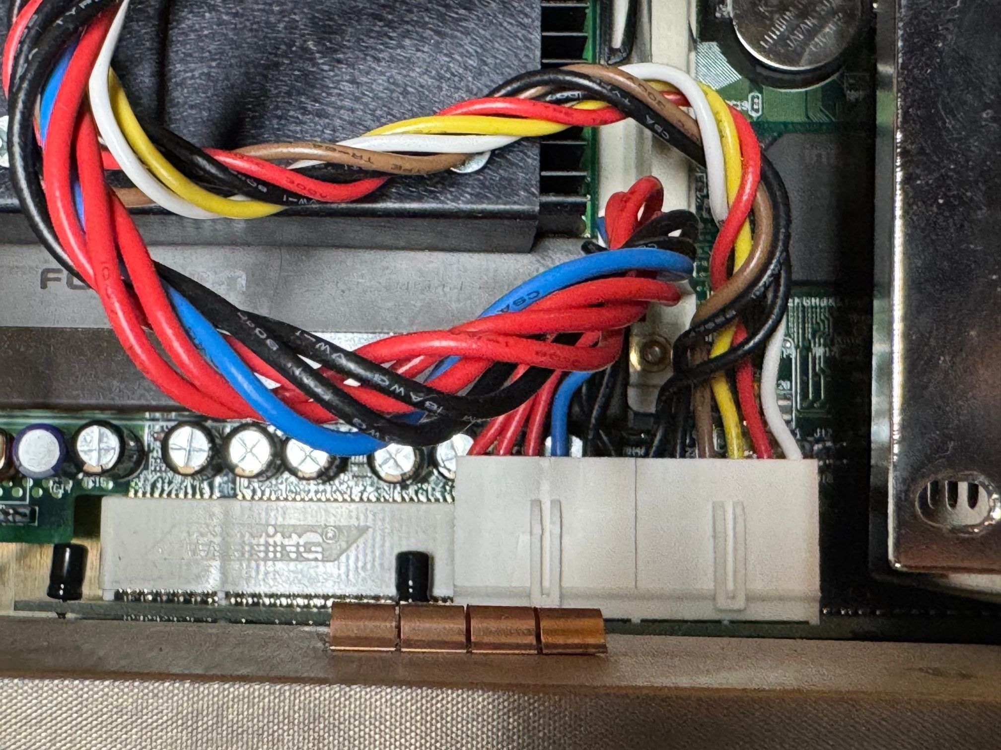
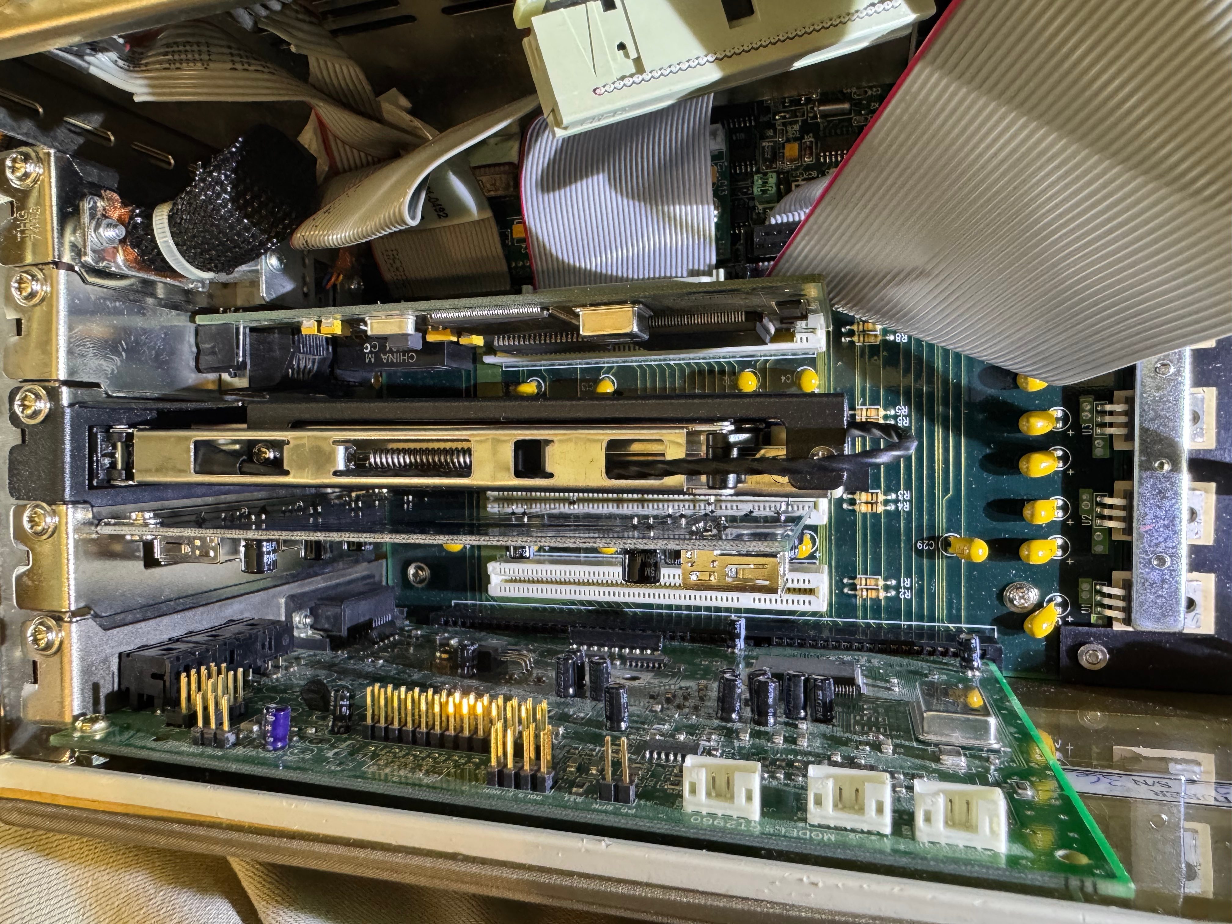
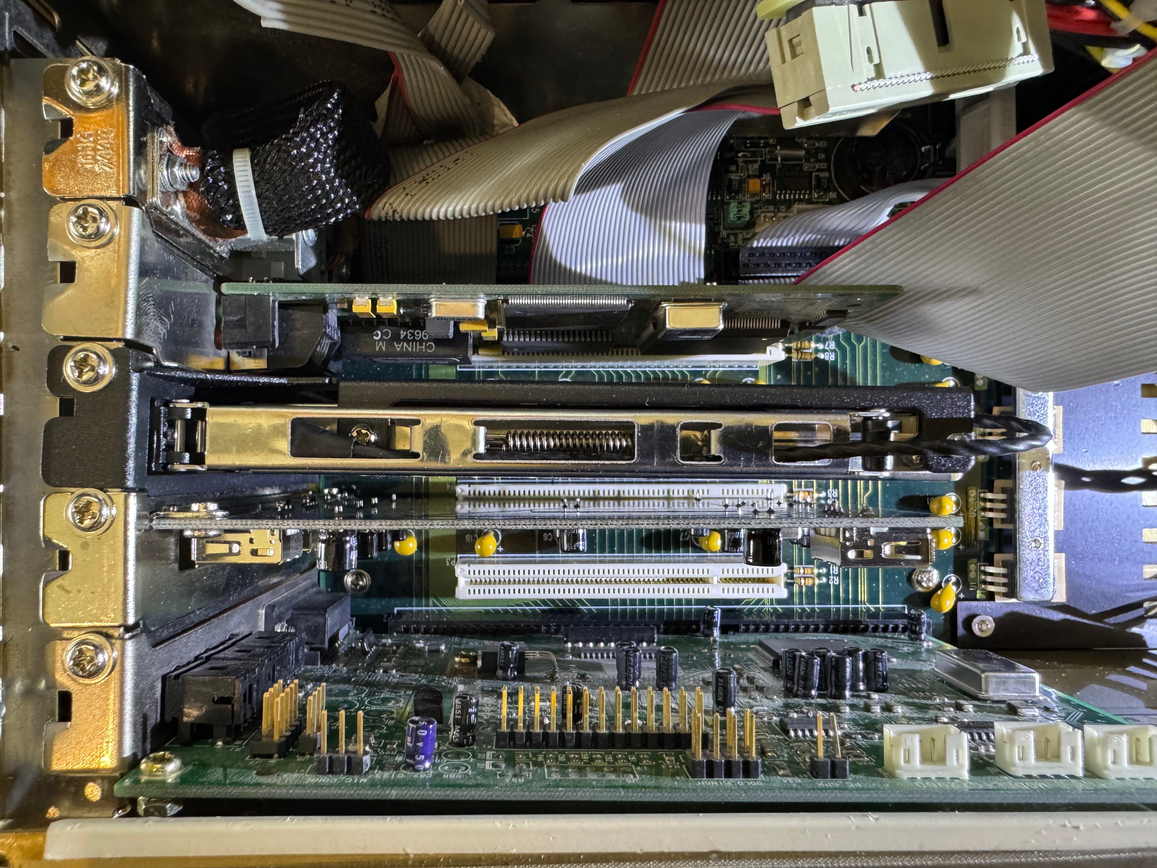
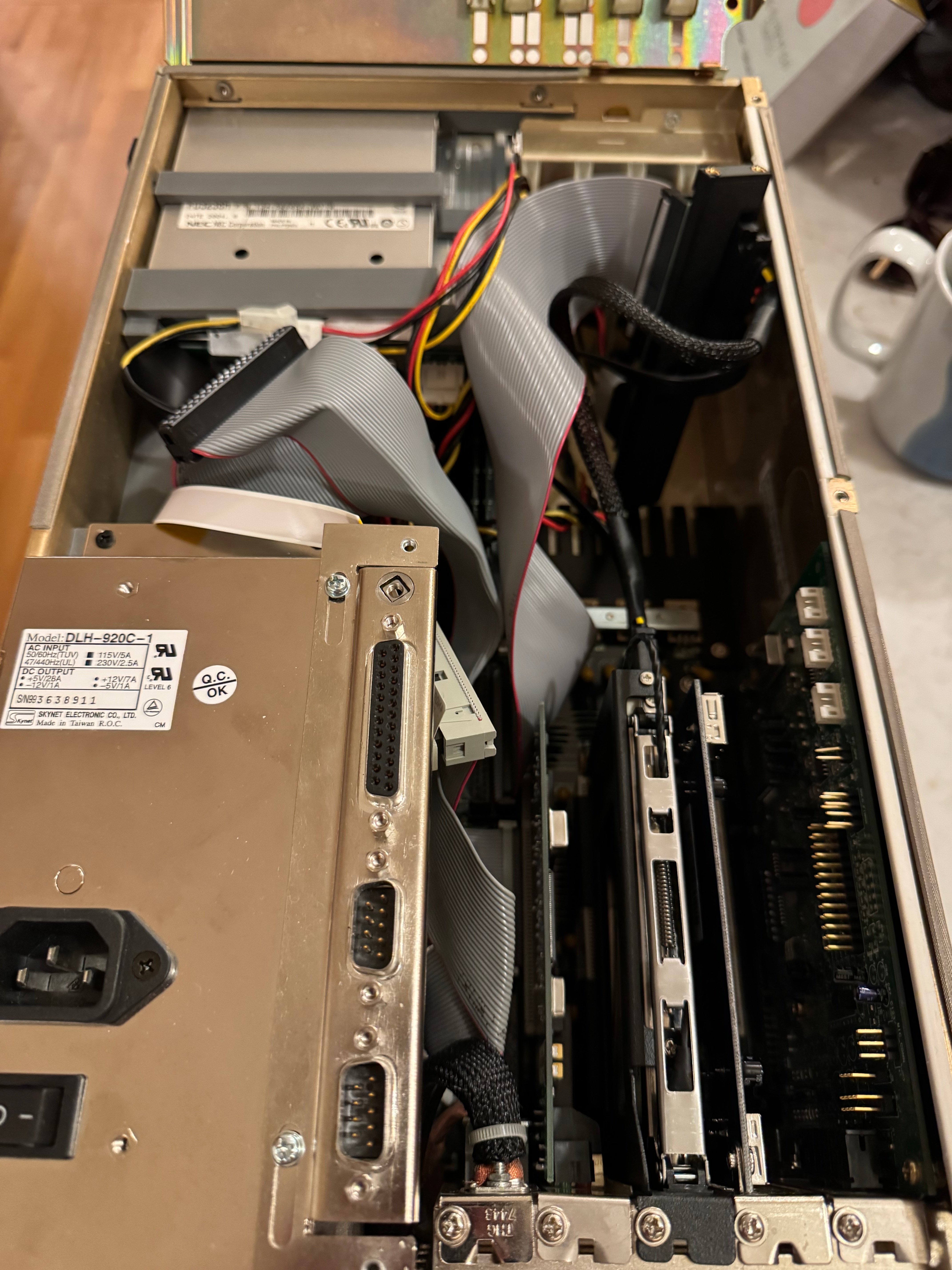
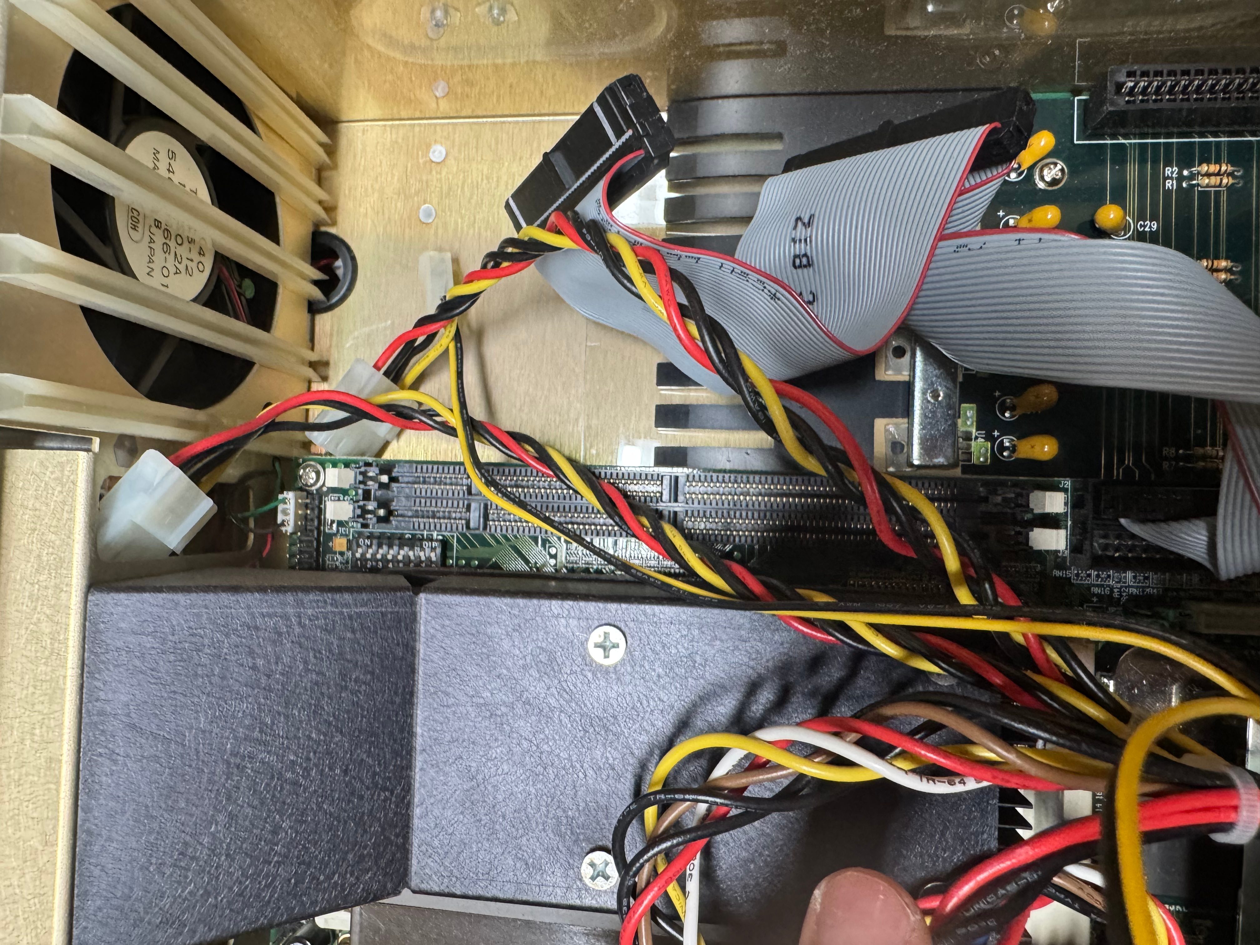
I was right! The motherboard was there! It had no disk drives, no RAM, no hard drive; it was perfect. A blank slate. The system definitely has some oddities. The motherboard is more of an industrial system, all on one board with CPU, memory, disk controller, ethernet, video card all together. Then a connector to another board that holds the ISA and PCI slots. My guess is it’s a PICMG or similar system. Being from that era, and a more industrial system, the fan is a 120-volt fan that always runs at a relatively high speed. I haven’t replaced it yet, but that may be on the shorter list of parts to swap out for a good quality of life improvement.

I need to thank Curious Marc! He also has this system, documented it well, and collected/uploaded all the drivers! This made getting the system online a good amount easier. He also has tables about the different RAM types it supports and information about the motherboard that got me moving a lot quicker on this project.

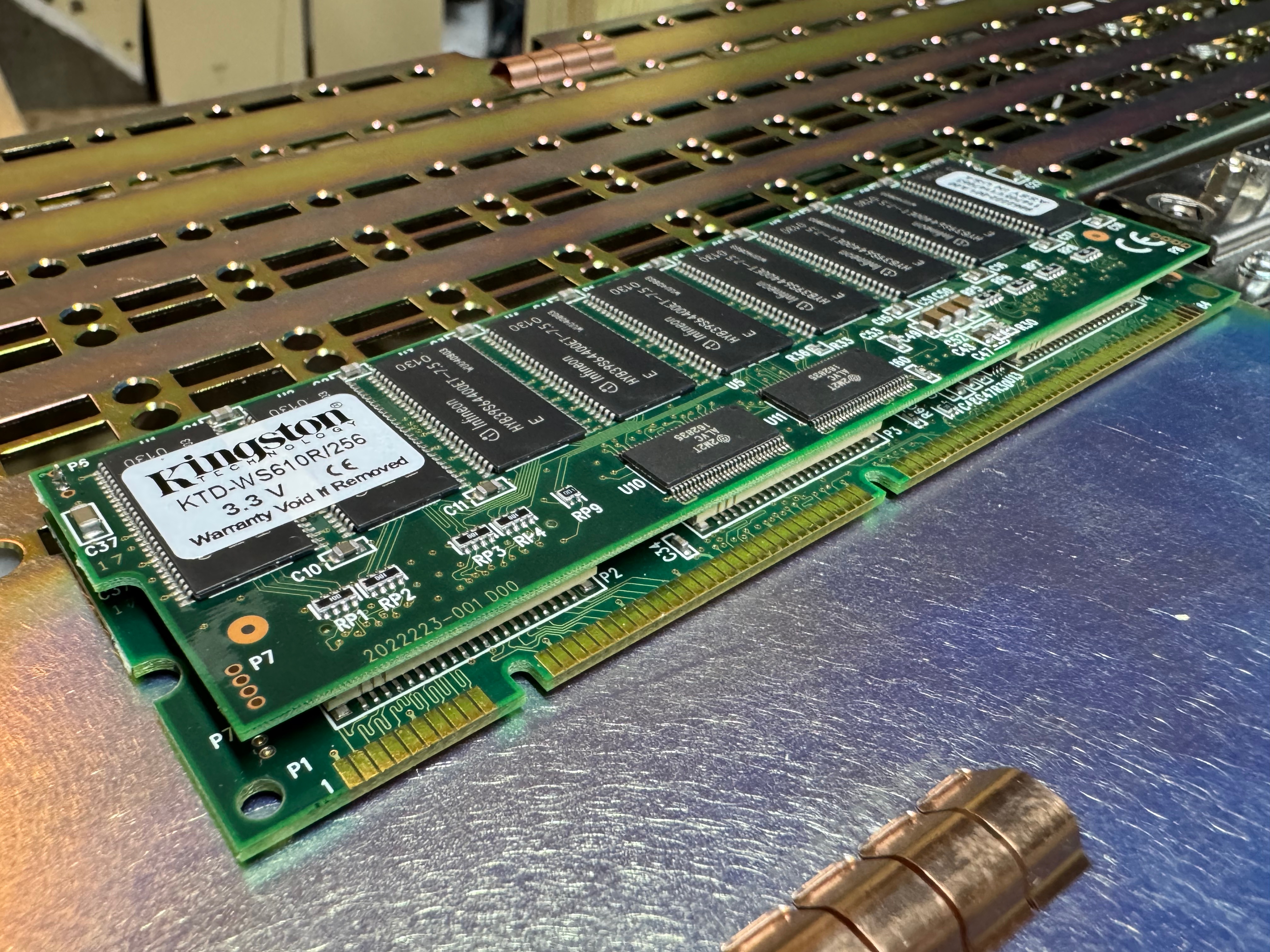
The first step was to get some memory to prove the system could POST. I found the system could use PC100 SDRAM, up to 256MB a stick for buffered RAM (128MB for un-buffered)! The KTD-WS610R/256 Kingston RAM ($7.50) I got was very interesting, it’s a multi-PCB board, joined together. I ordered just one for now, 256MB is plenty for this machine. I am currently using one of the two DIMM slots the machine has.

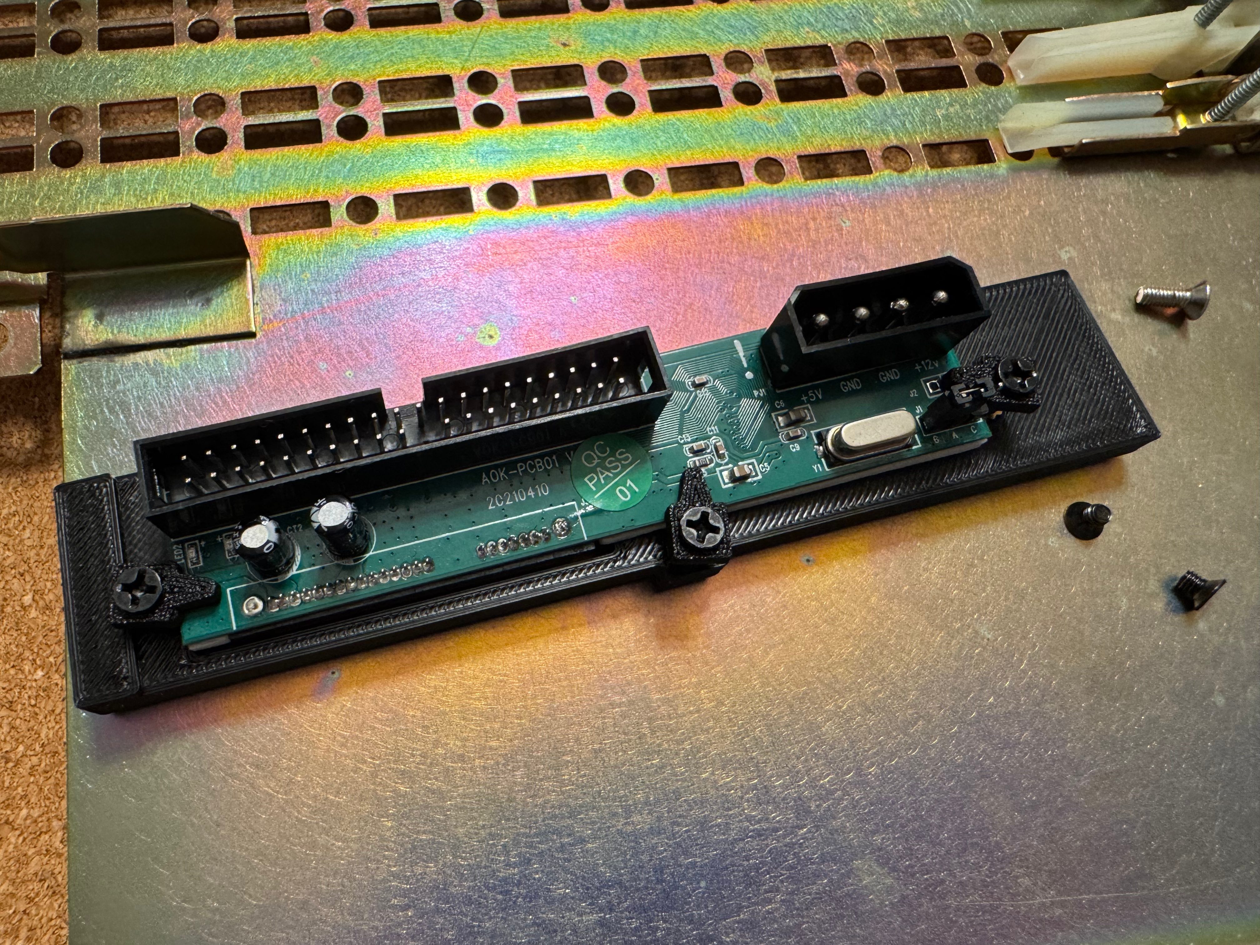
With that, we got the system to POST! It needed a new CMOS battery, but what system this age doesn’t? It was happy! Now I needed a hard drive, some disk drives, and expansion cards. For a hard drive I got a modern SATA SSD, and a SATA to IDE adapter. I put the drive in a spring loaded enclosure that goes into one of the PCI slots; this lets me remove the drive easily if I want to. I would pull the drive to add files before I got networking loaded from time to time. I later added USB, but the system couldn’t boot from that, and burning CDs wasn’t always my go-to.

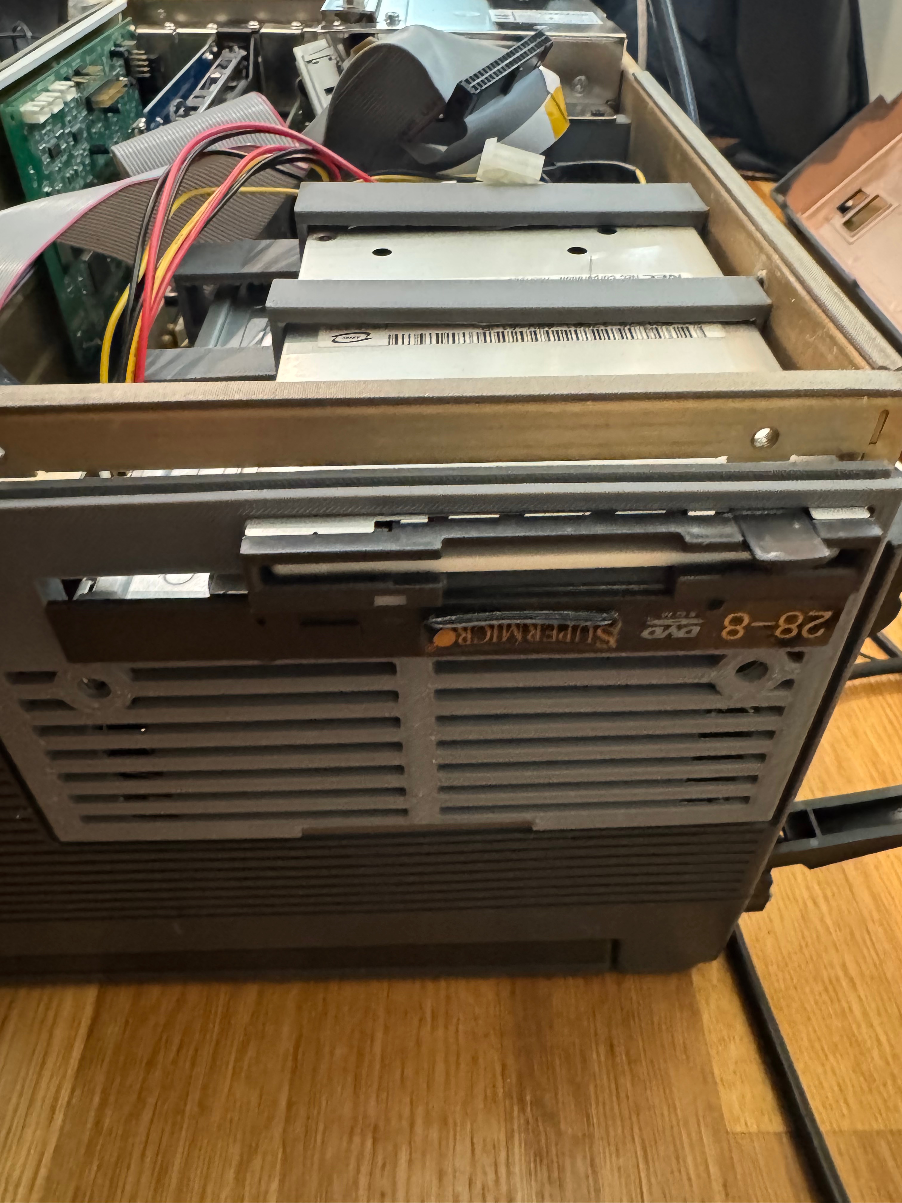
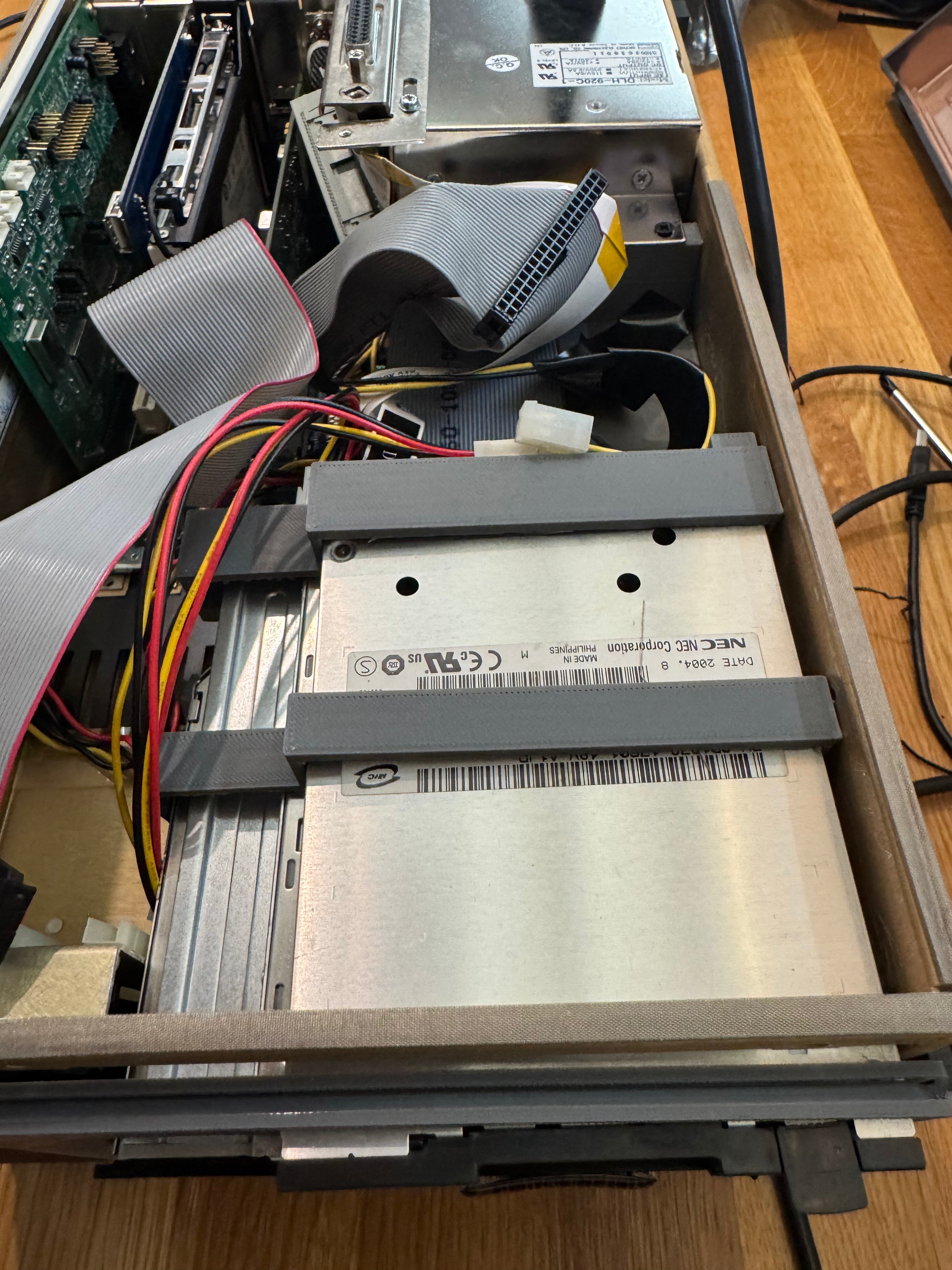
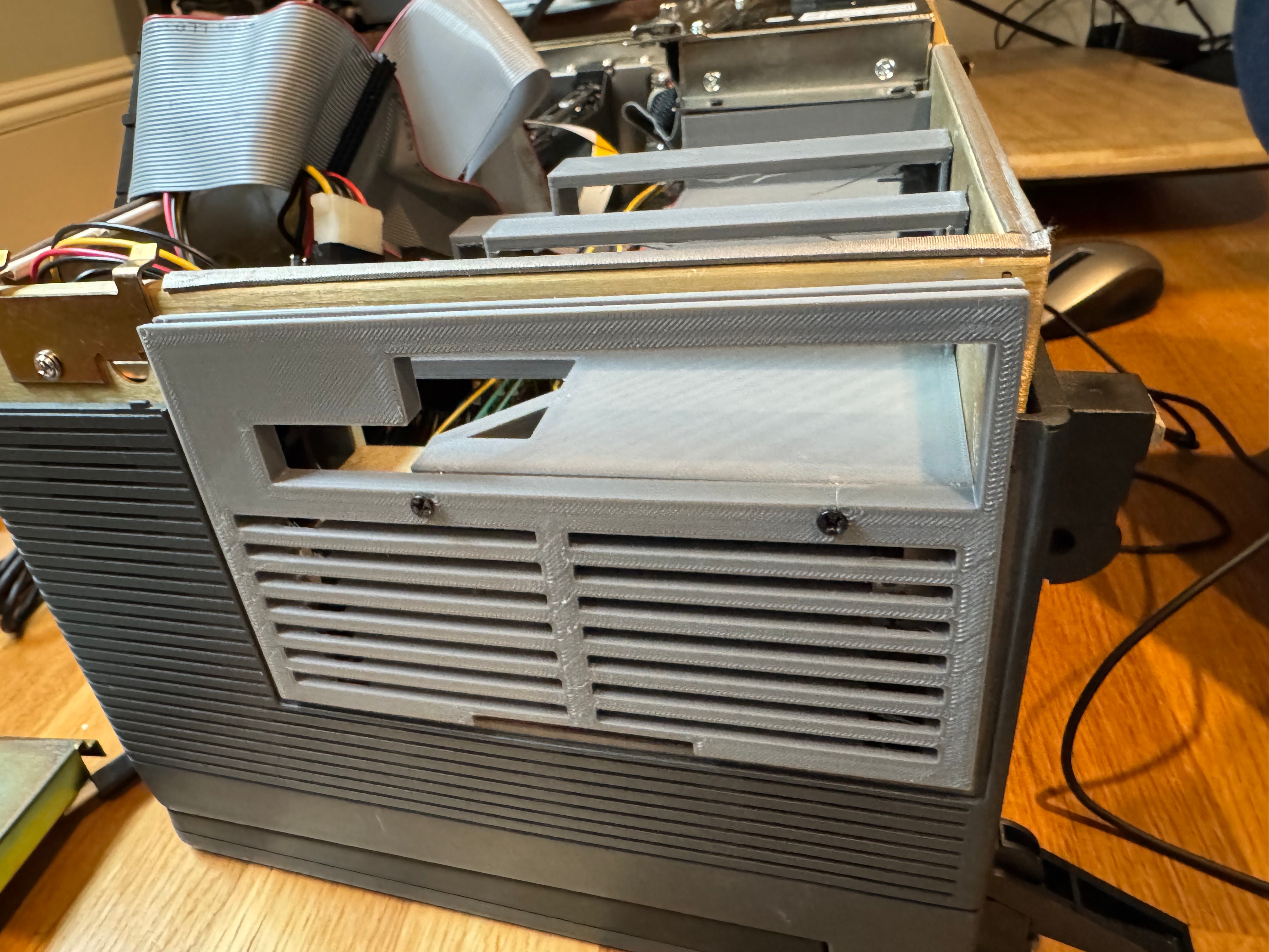
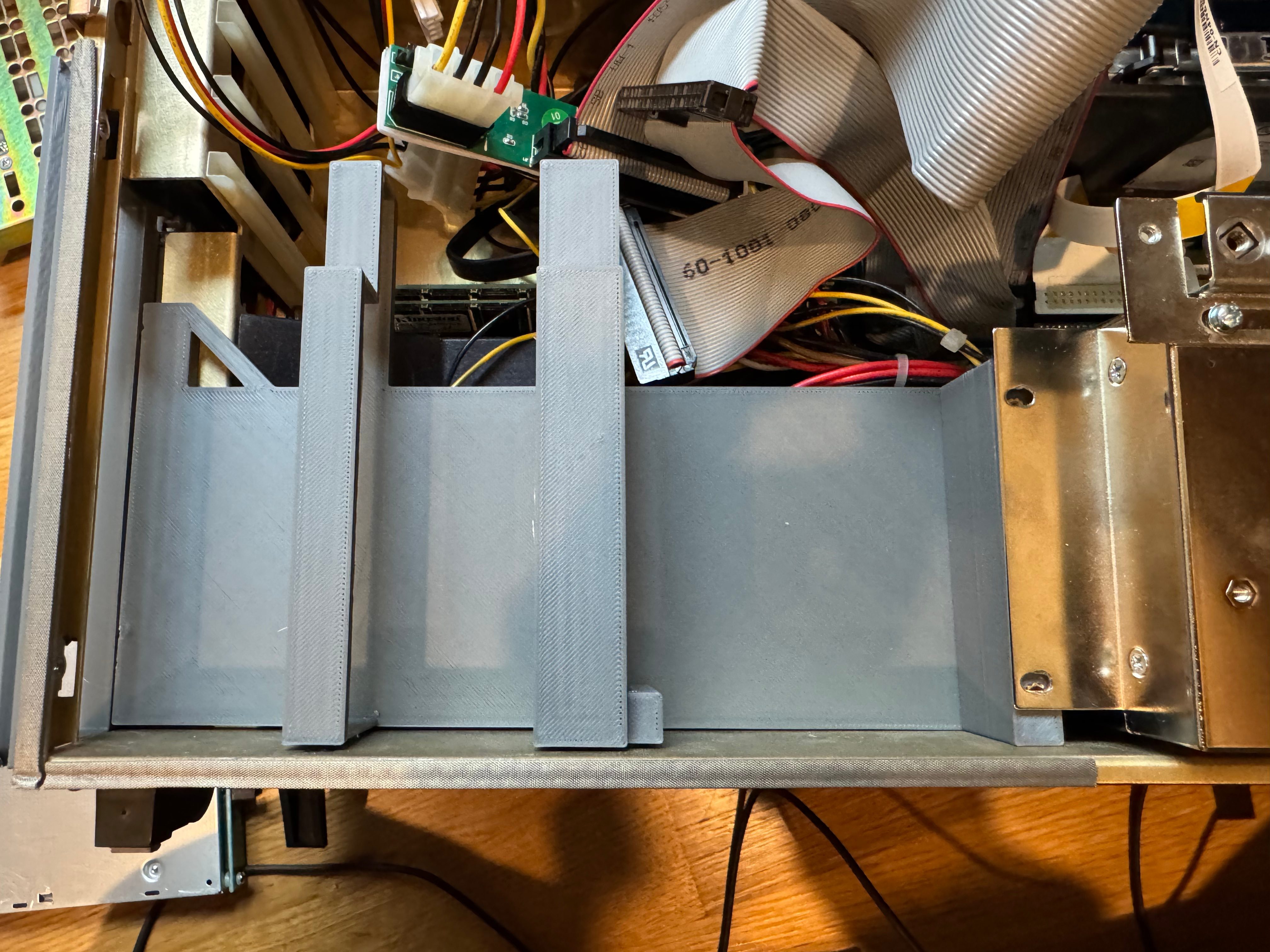
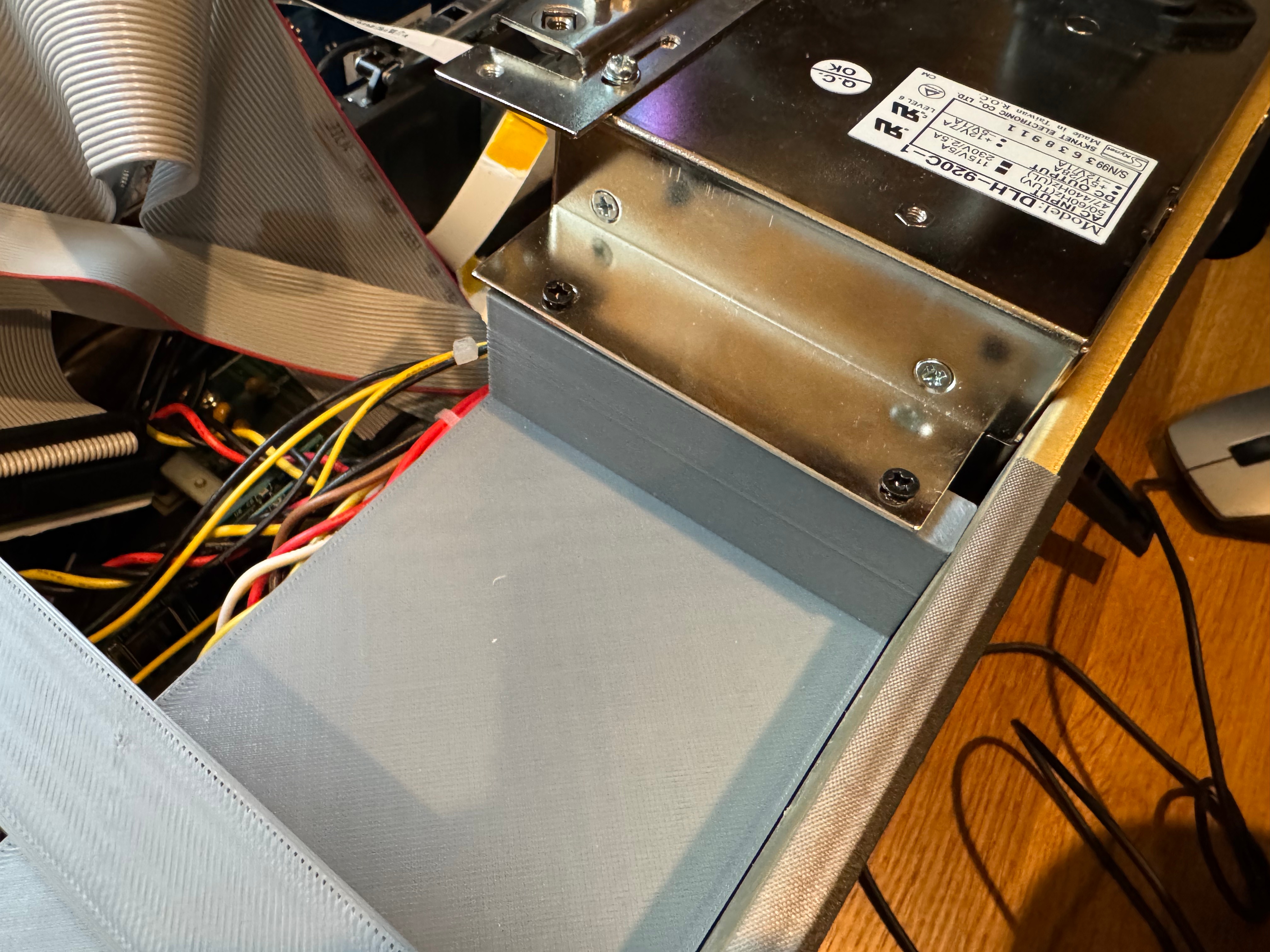
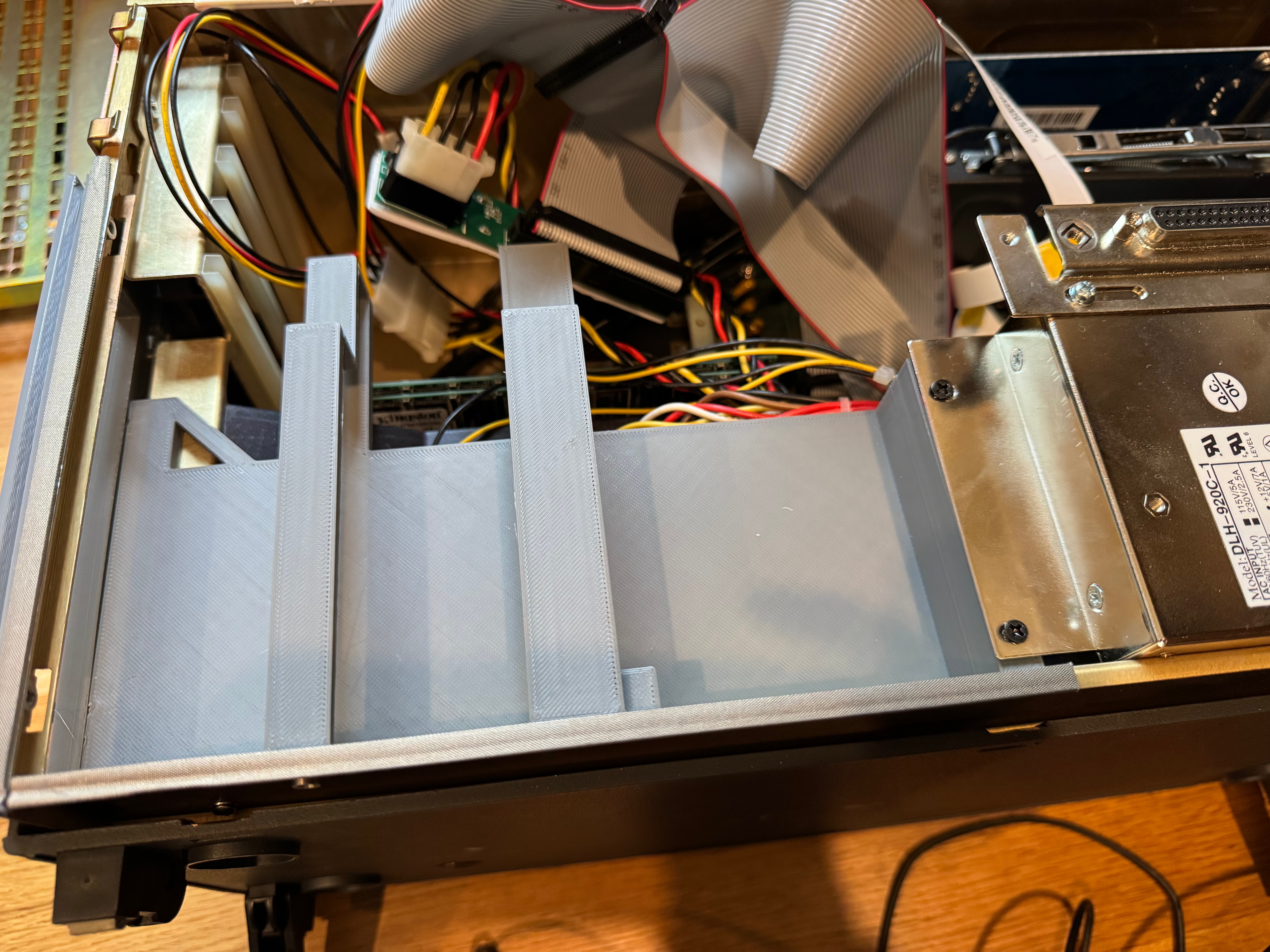
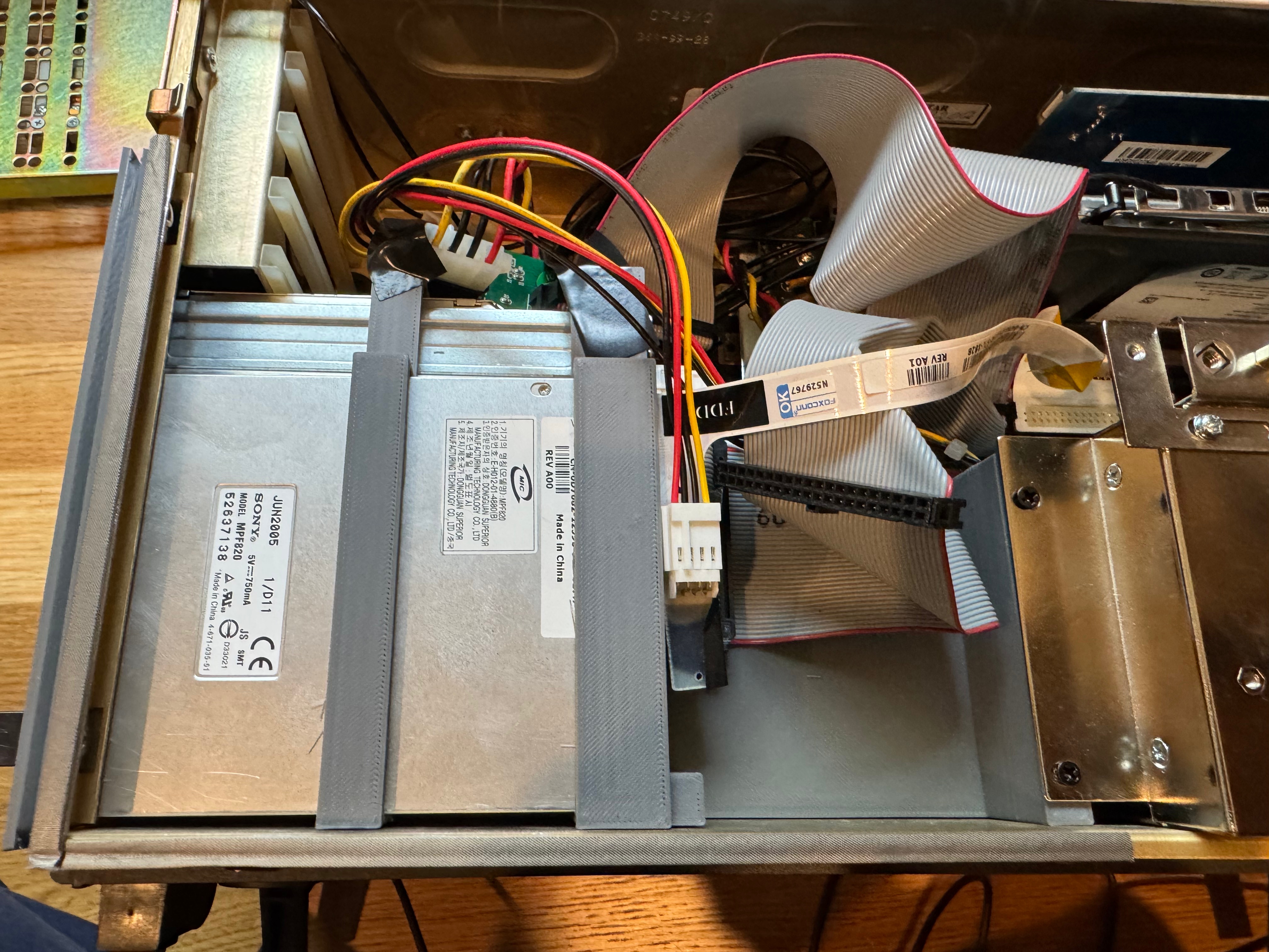
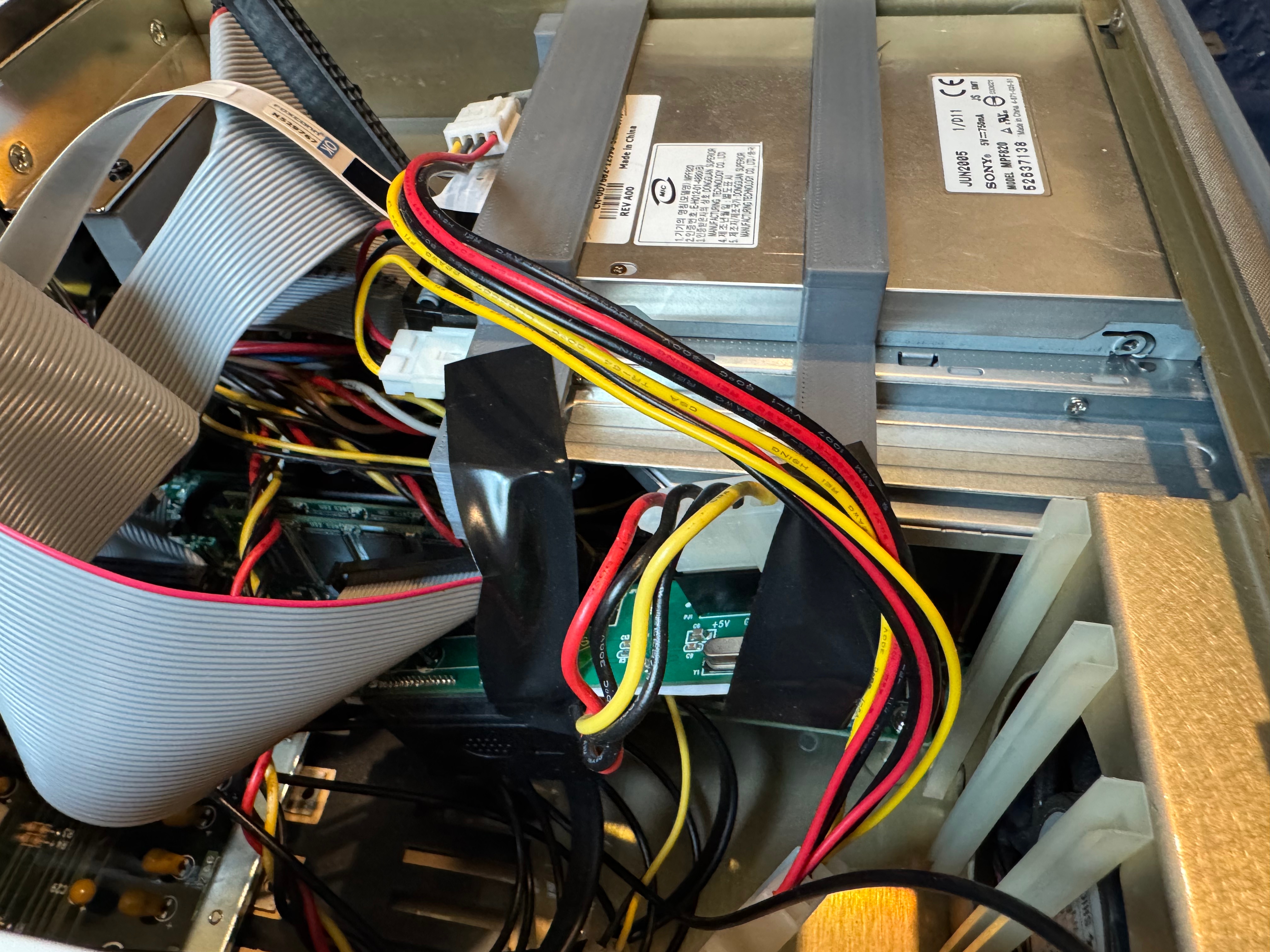
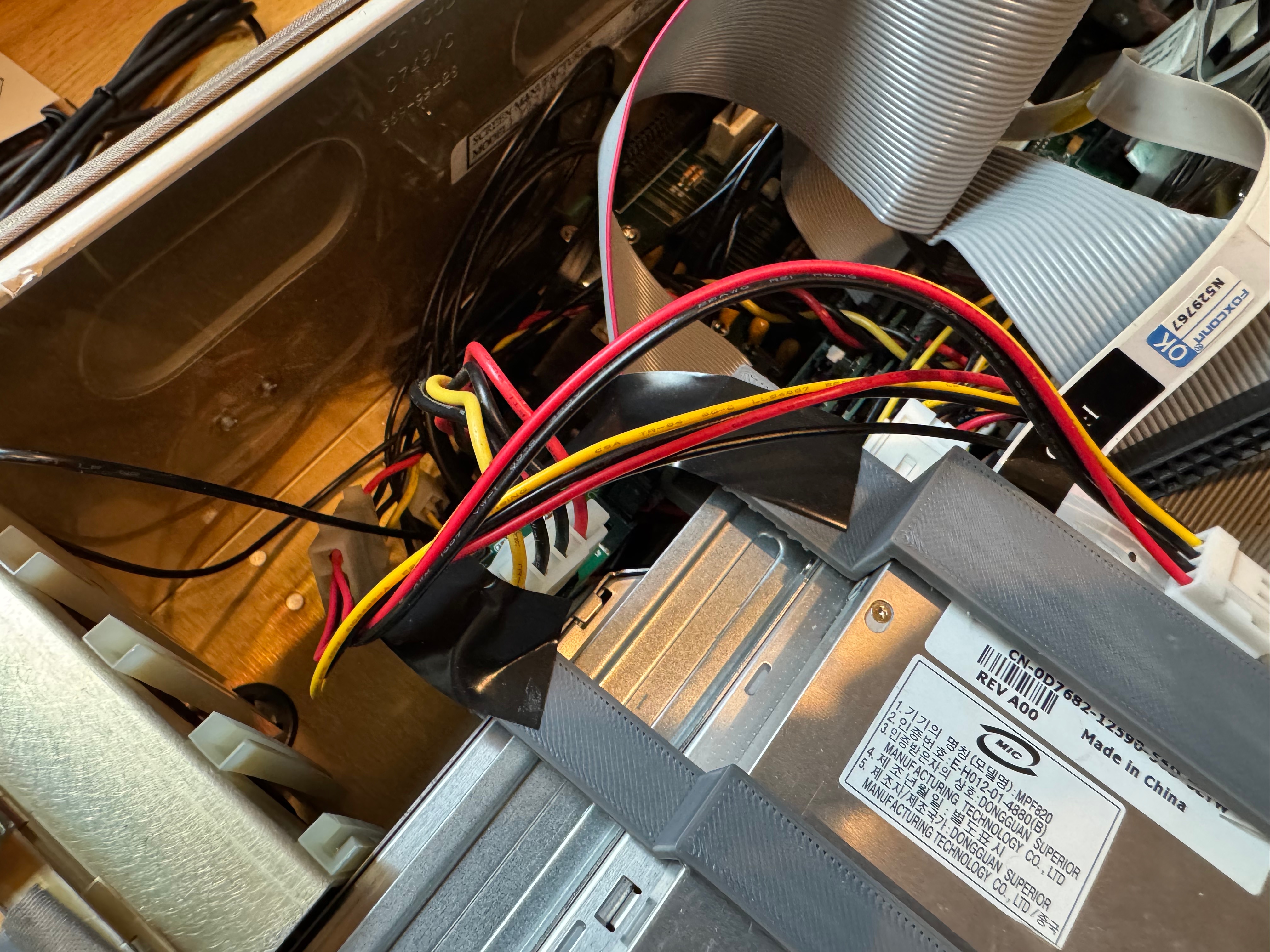
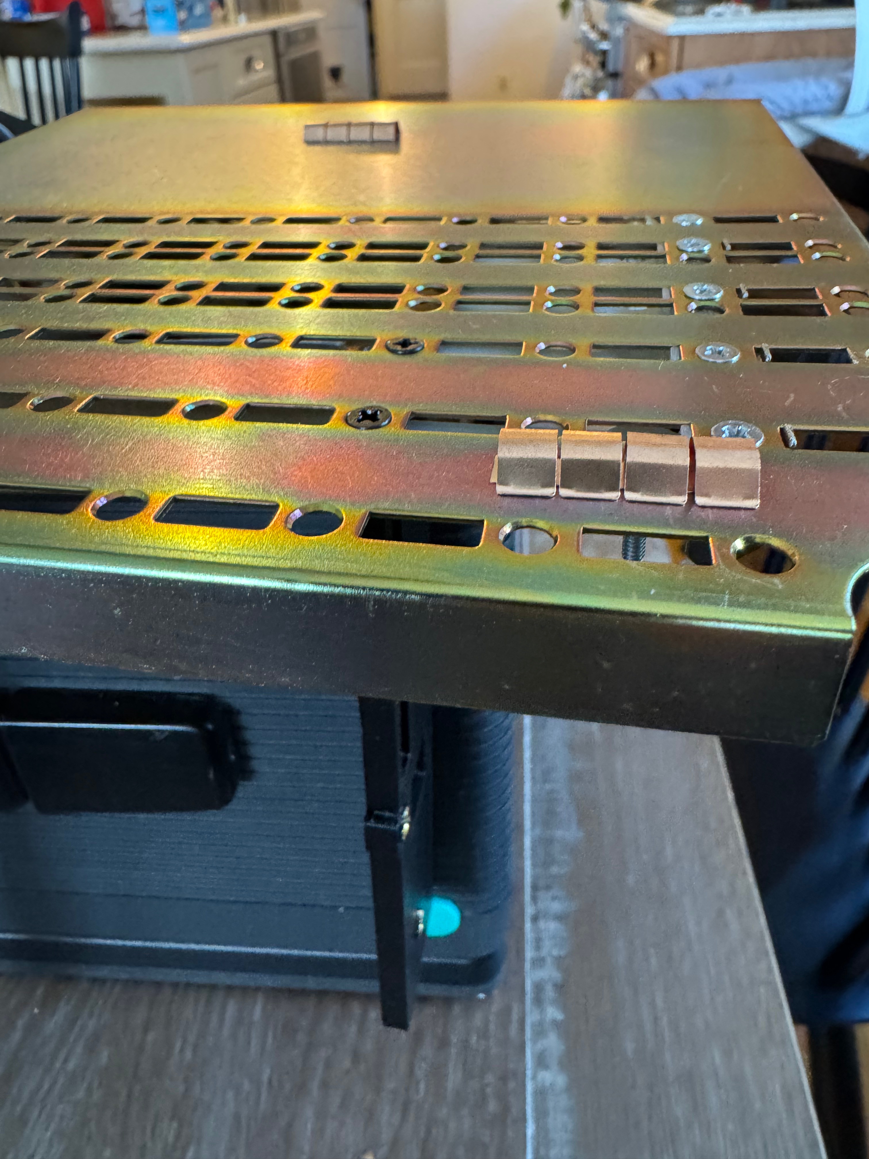
Then I got a slim fit IDE DVD-ROM, and a laptop floppy drive. That let me burn Windows 98 SE to a blank CD and start installation. I also ran memory tests and stress tests on it just to be sure the system in “unknown” condition was doing OK. Now that I had those external drives, I had to start making some brackets. The original hard drive bracket and the optical/floppy bracket were missing when I got the system.

I pondered which operating system to put on the machine. With a 400MHz Pentium II, Windows 95 and 98 were the more obvious choices. The spring-loaded enclosure and optical drive make installing a new operating system not too difficult. To begin its new life (with me) I decided to go with Windows 98 SE. I get USB support right away, FAT32 for more storage, and generally better driver support. There are a lot of community patch kits, Windows Service Packs – PHILSCOMPUTERLAB.COM, that help fix rough edges. Eventually I may install OS/2 for fun, or an older flavor of Linux.

The brackets turned out to be the hardest part of the whole restoration project. The actual system came together so easily that this is where a majority of the time went: dialing in the models for all the brackets.

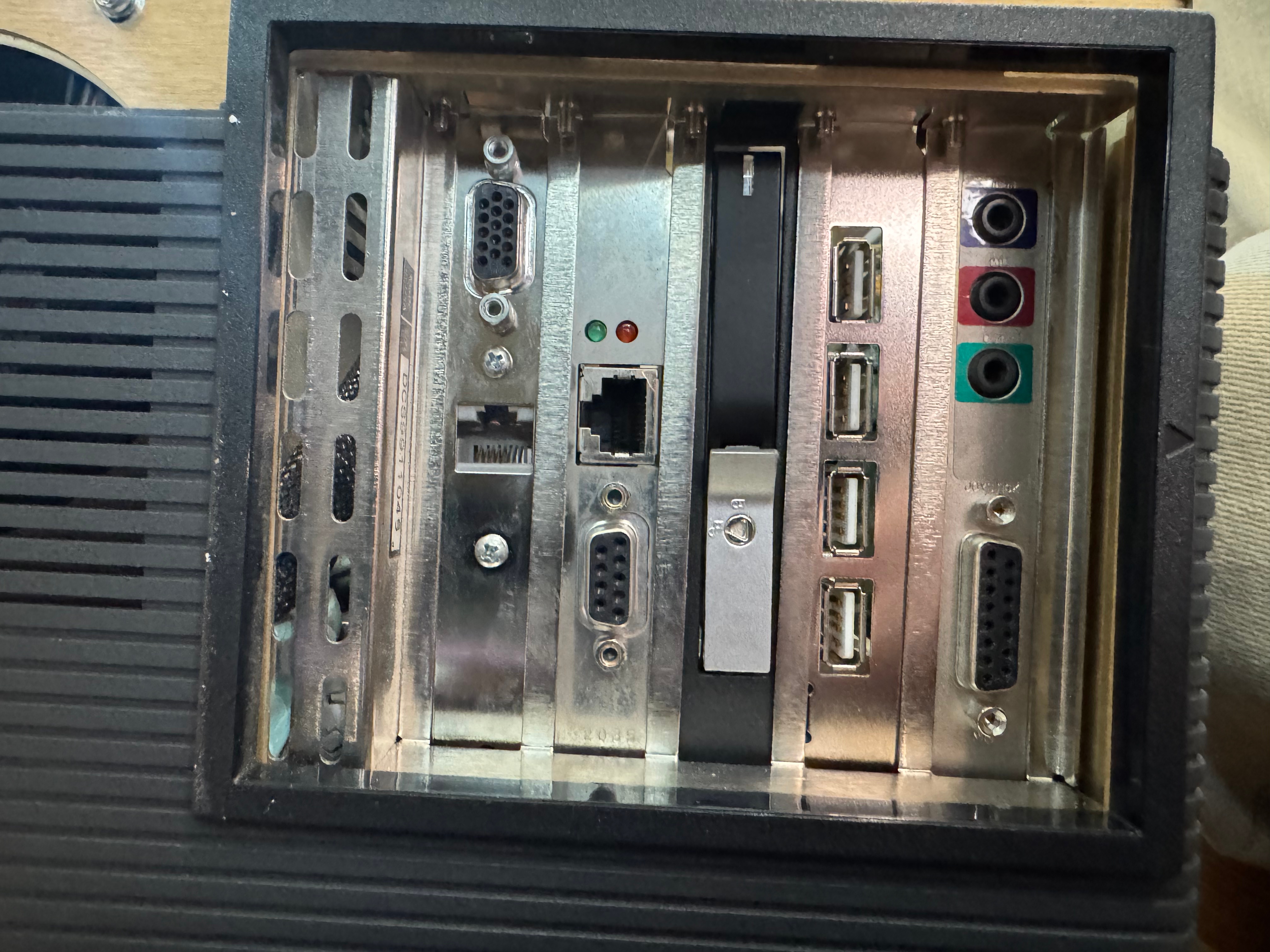
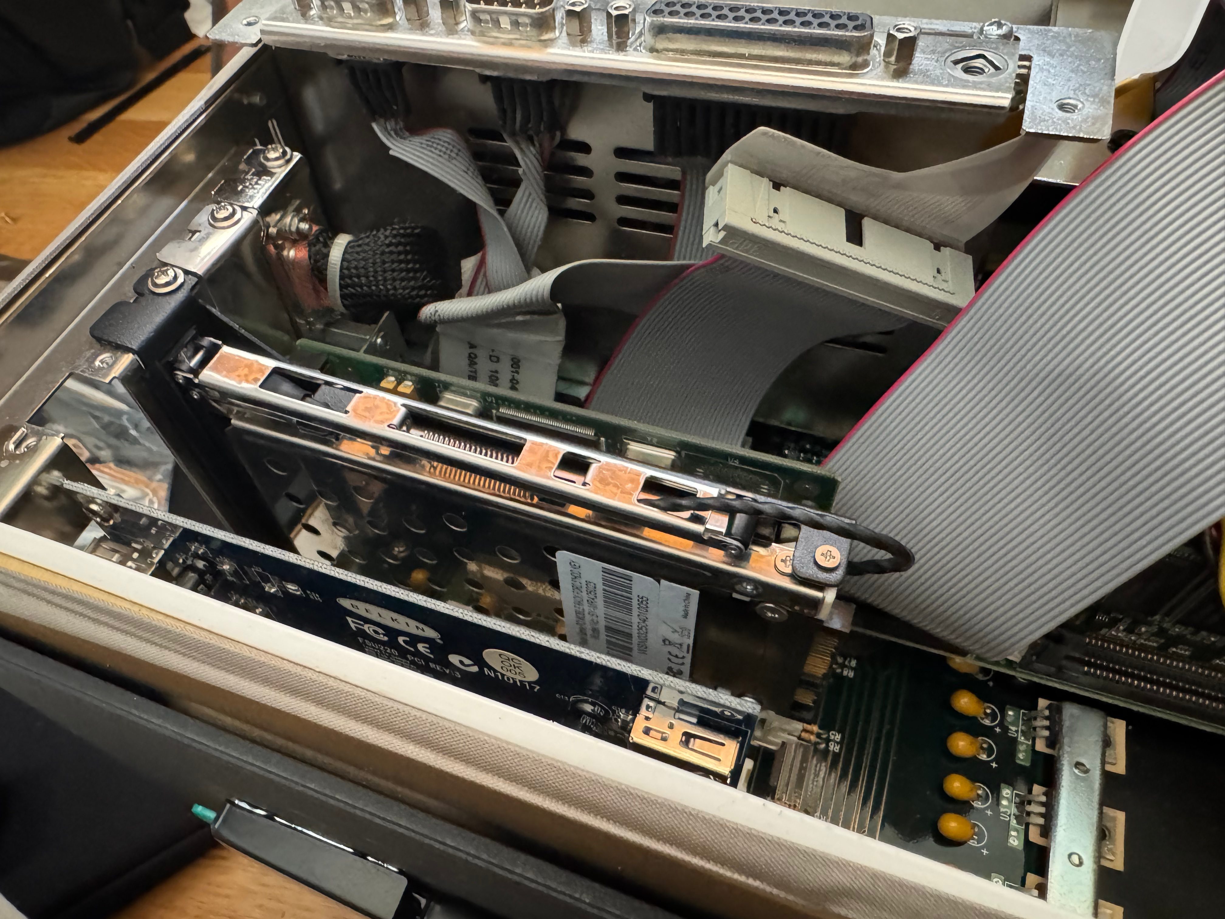
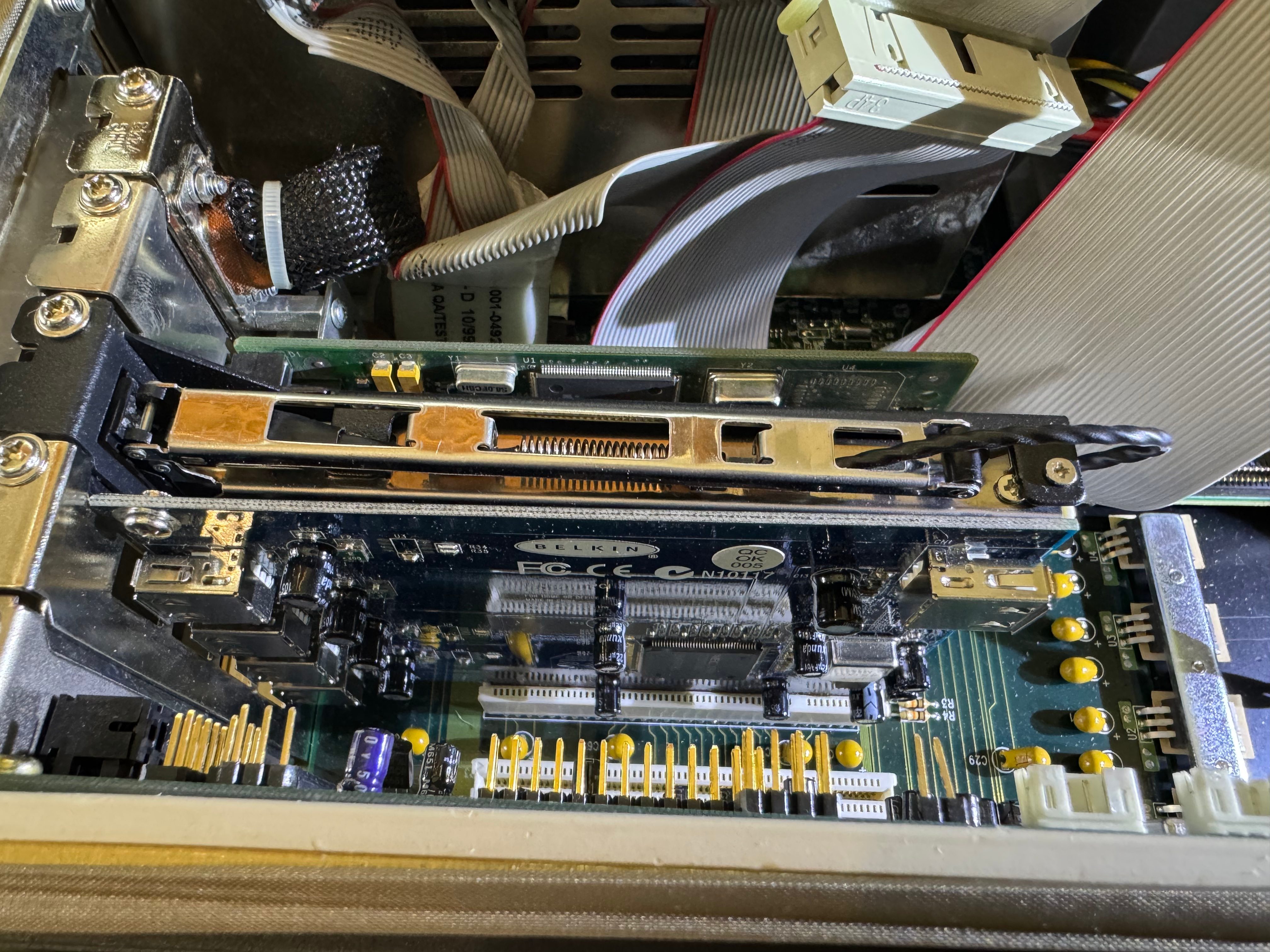
I then went to find some additional expansion cards to make my life easier, starting with a Belkin F5U220 USB 2.0. With USB mouse and storage support added, working within Windows 98 would be much easier. The little nub mouse works on the keyboard, but it’s not the most comfortable thing to use.

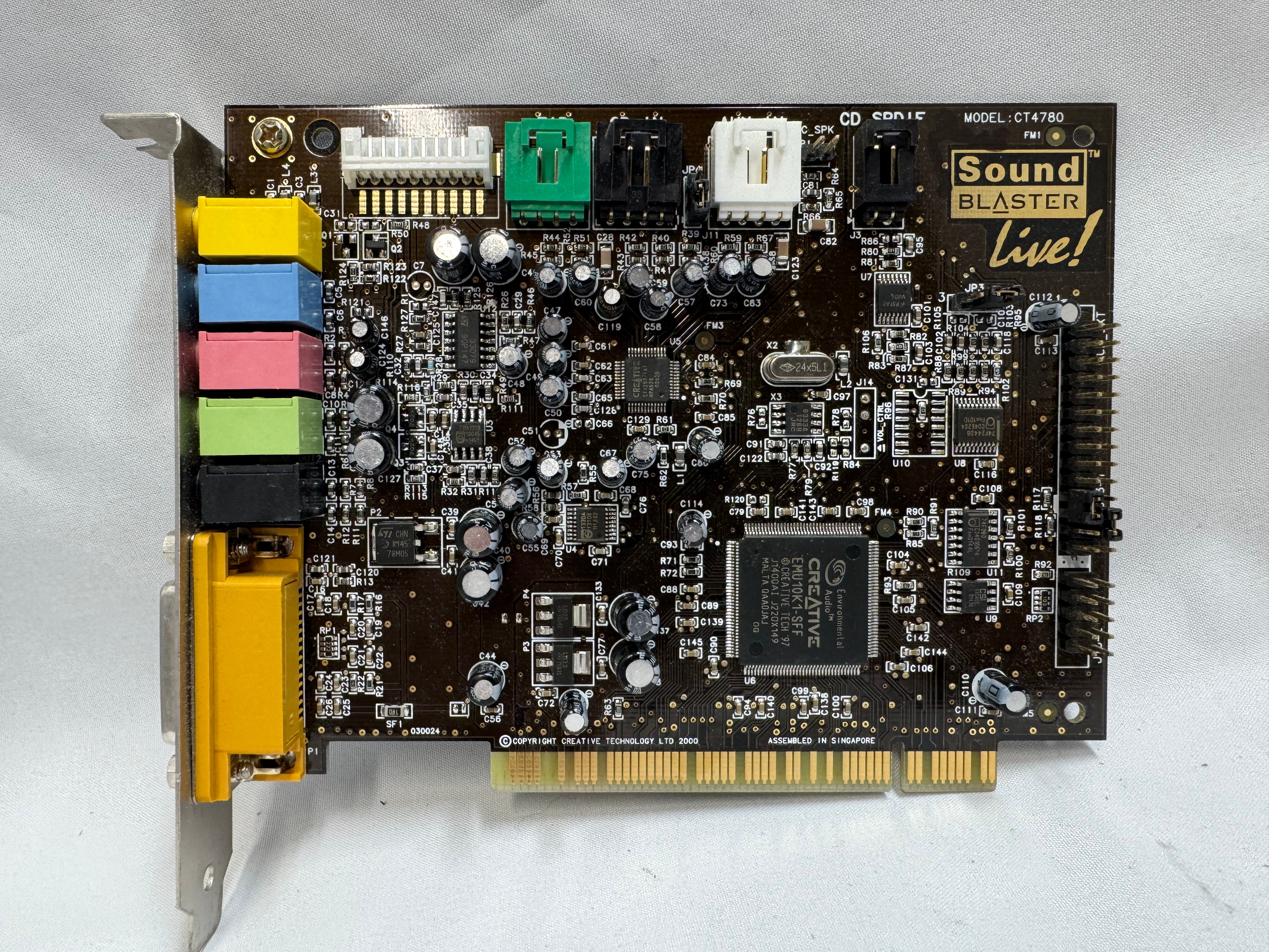
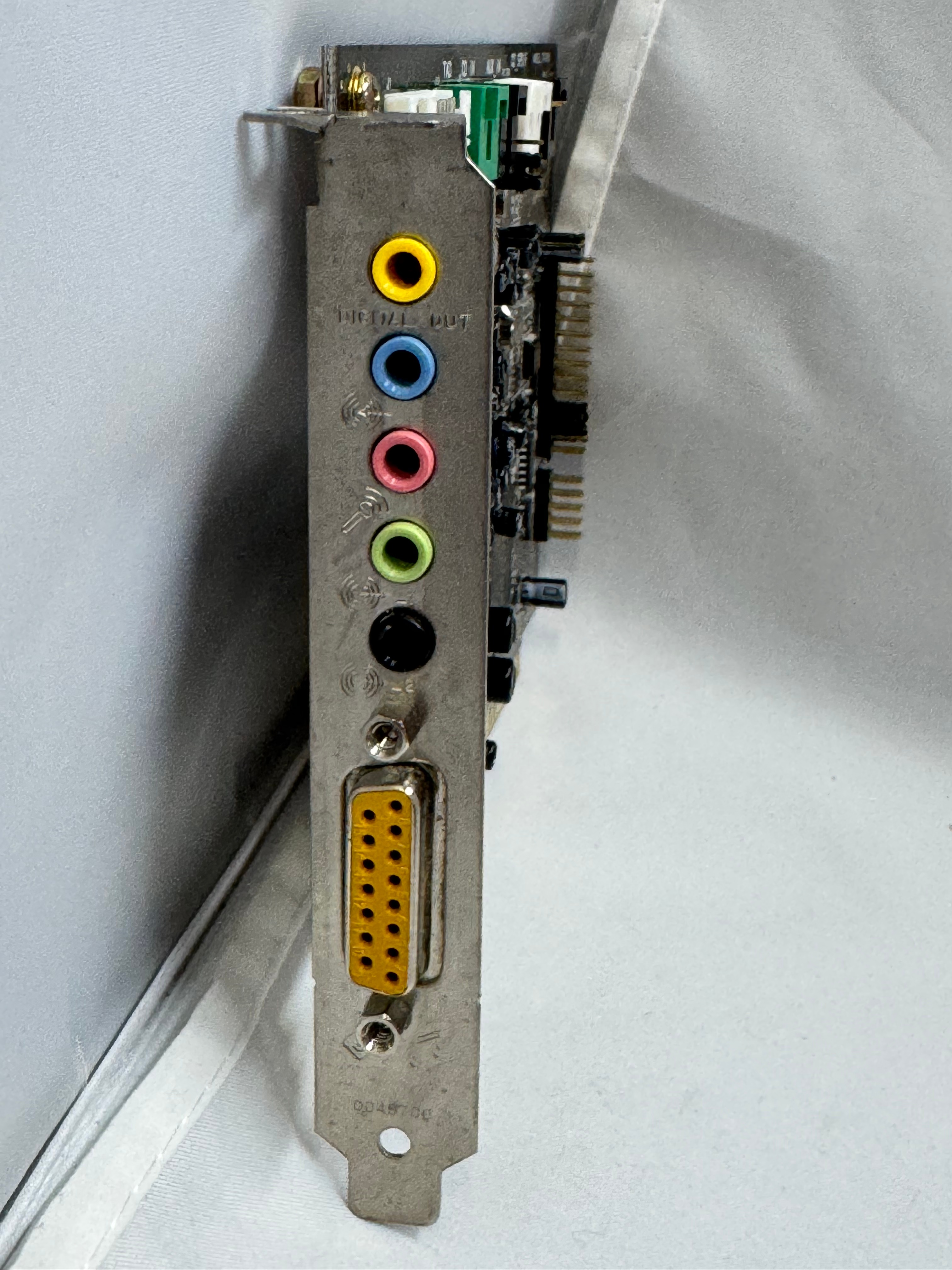
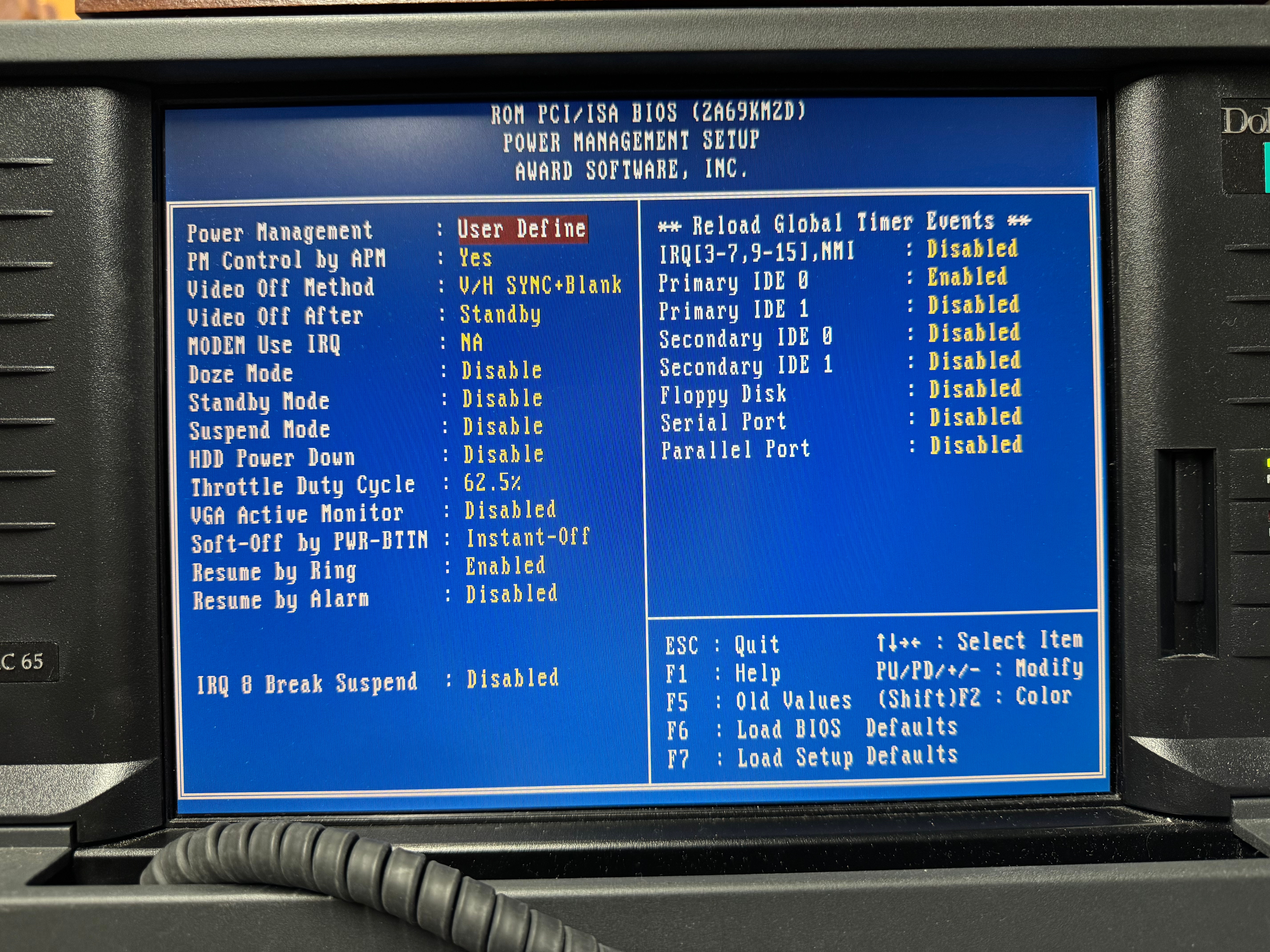
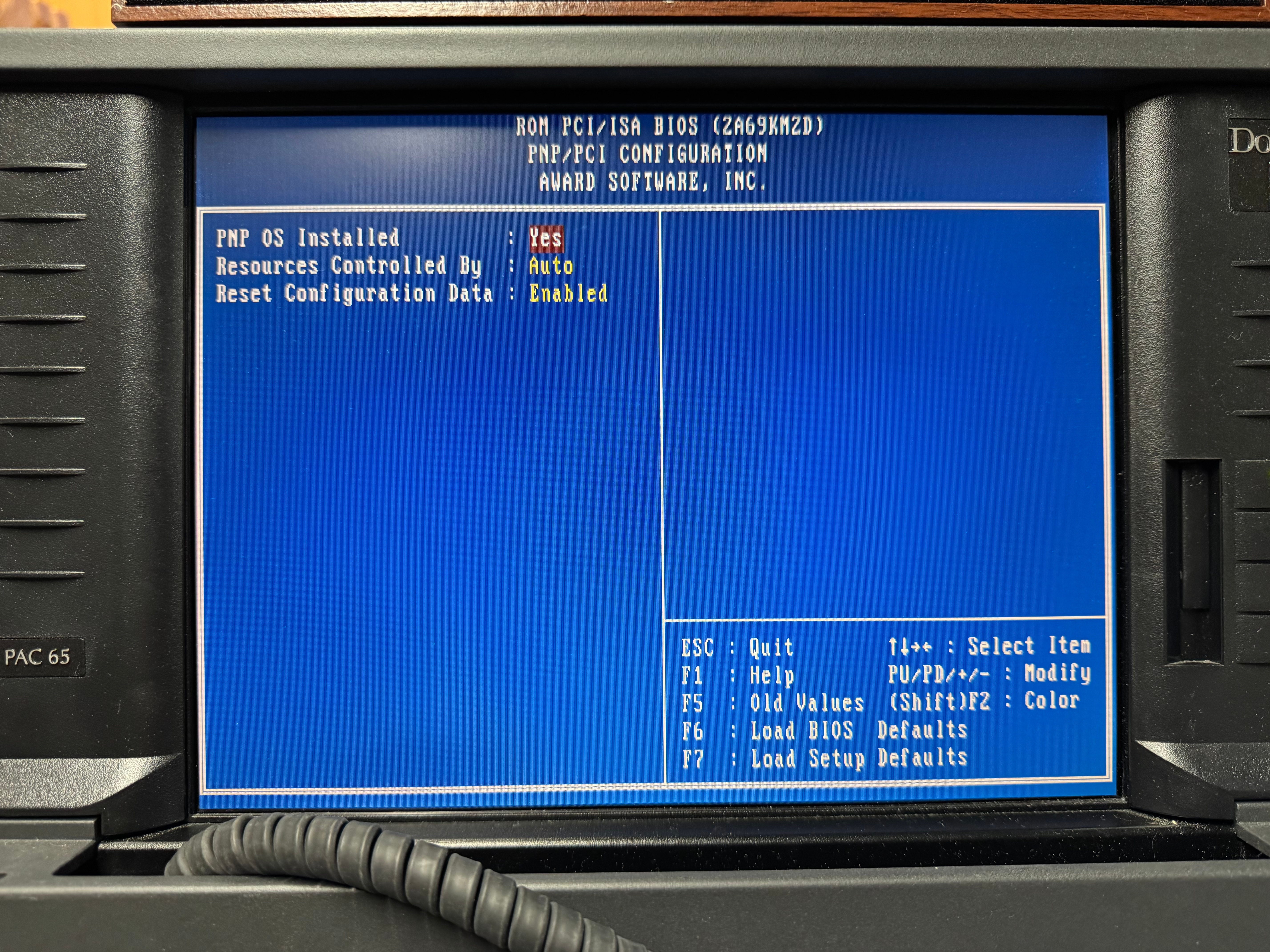
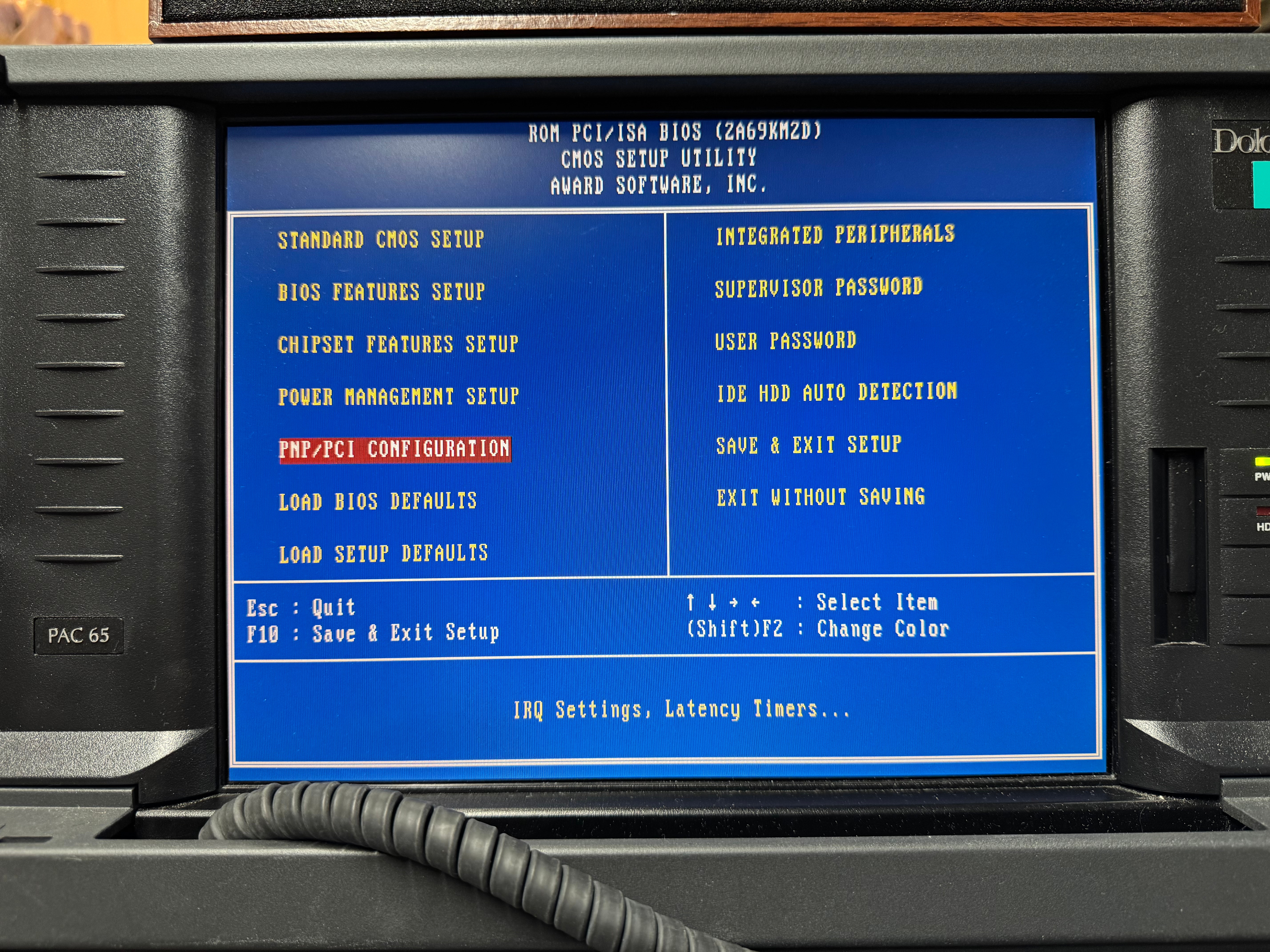
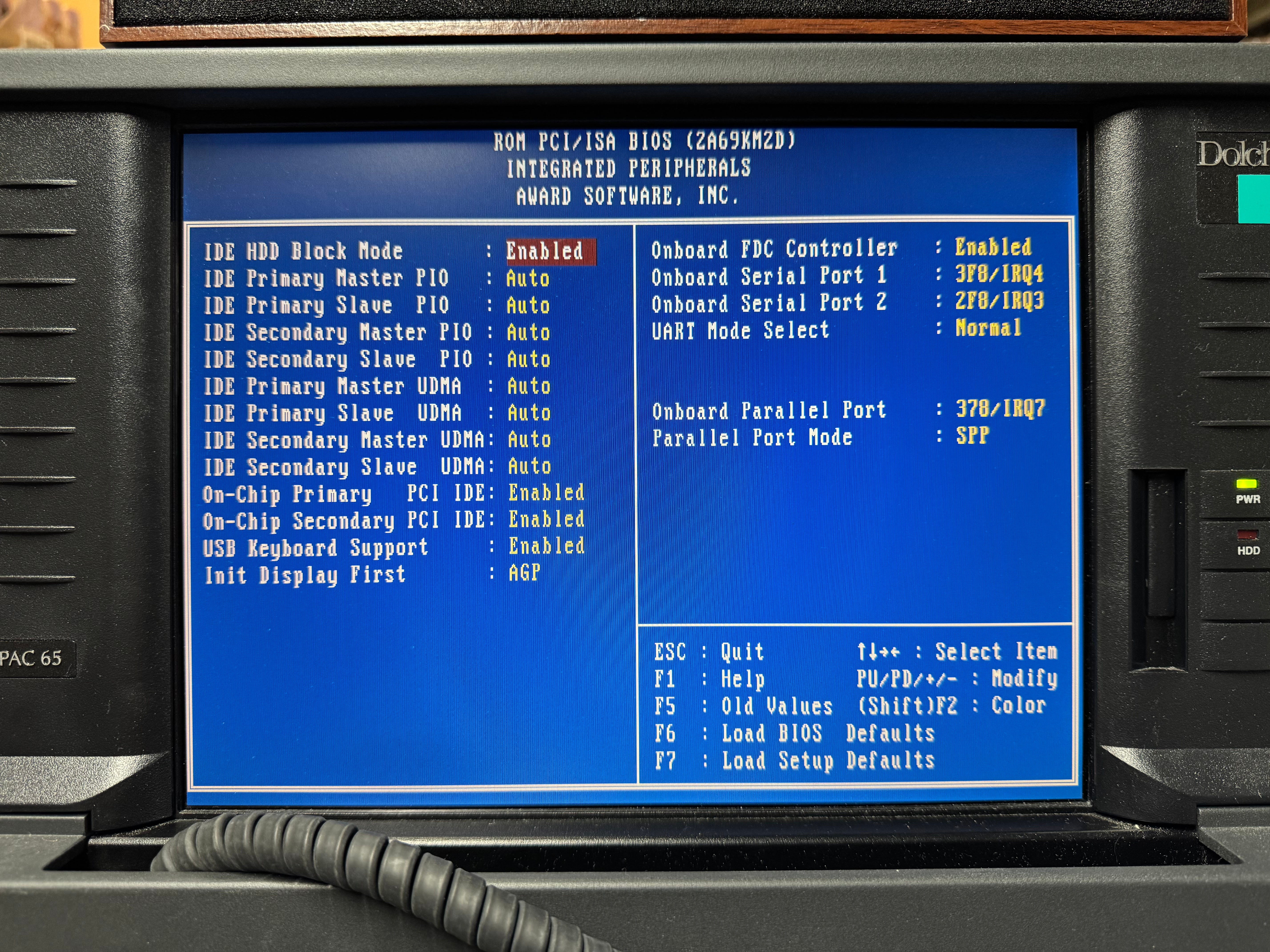
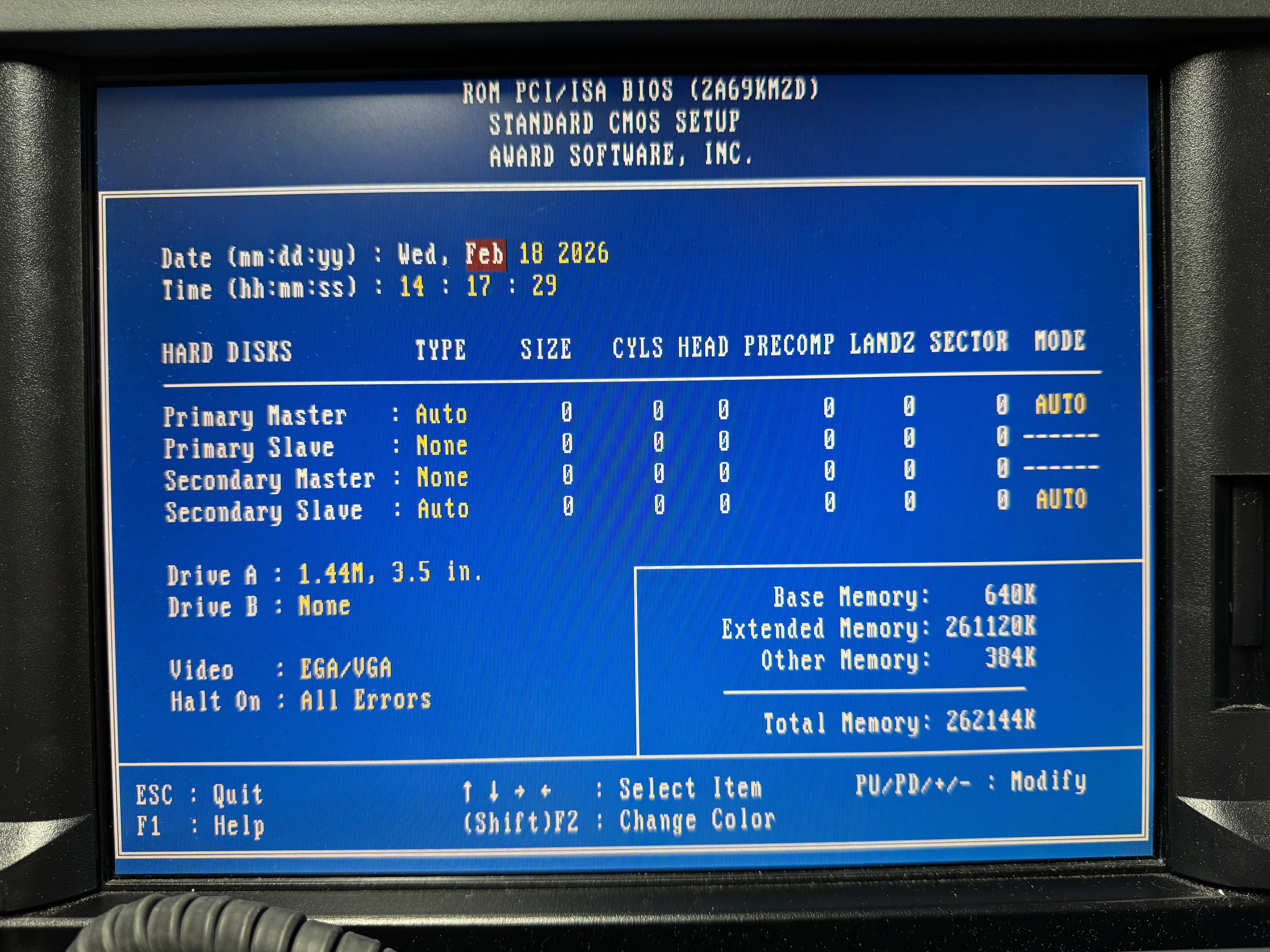
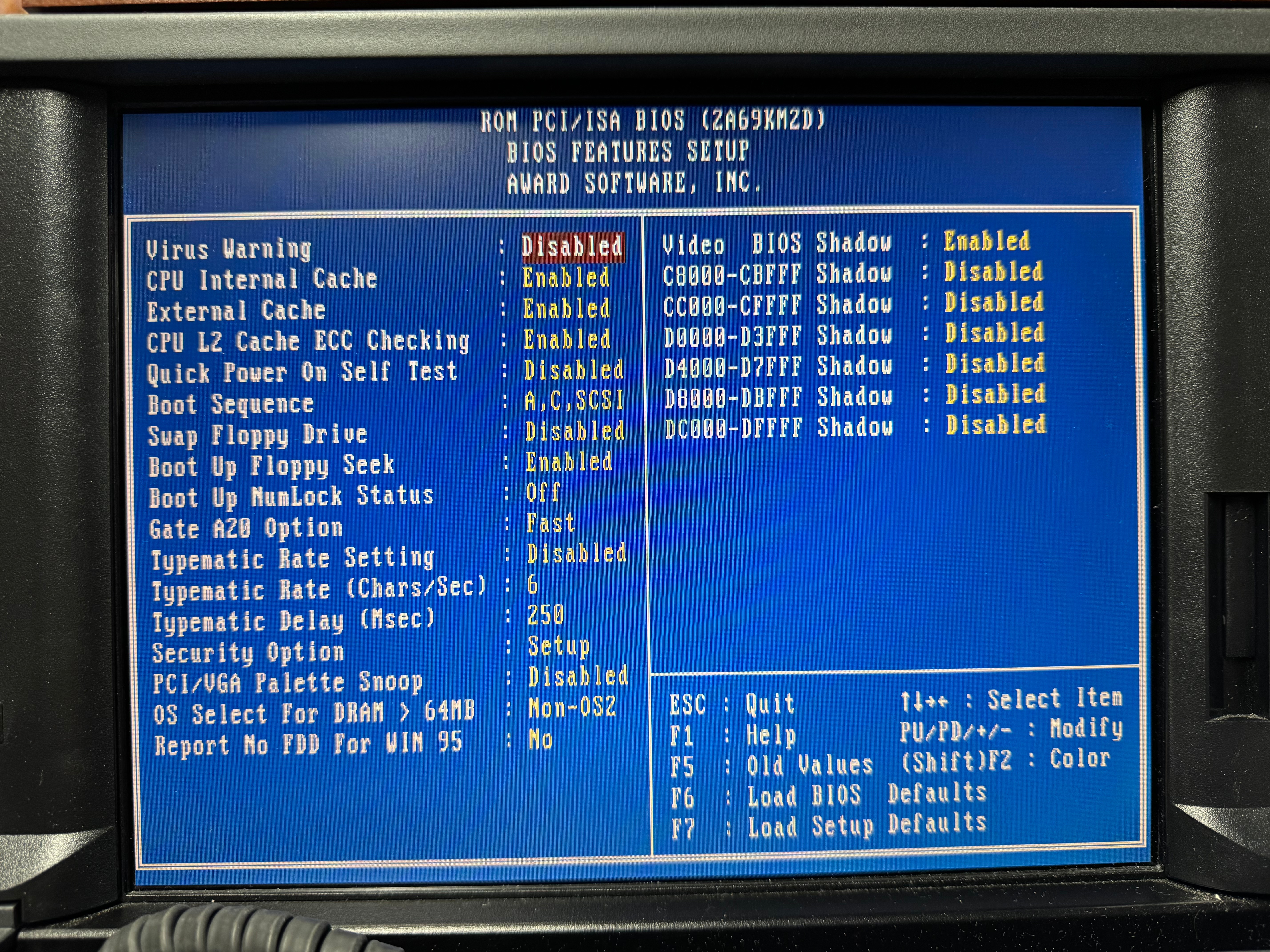
I wanted to get a Creative Sound Blaster, and I did off eBay. It was an authentic, old, ISA one that would work perfectly with all my DOS games. The issue I ran into was the ISA slot did not want to work. I am not sure if this is a later model, or maybe there is a jumper I couldn’t find on the motherboard that needs to be set for the ISA slot to work. There are many BIOS screens (screenshots below). I tried manually setting IRQ, automatic, no matter what Windows didn’t even see the card existed. After battling that for a little while, I gave in and got a PCI Sound Blaster. Using Windows 98 made this easier than older operating systems would have. That one worked immediately when plugged in.

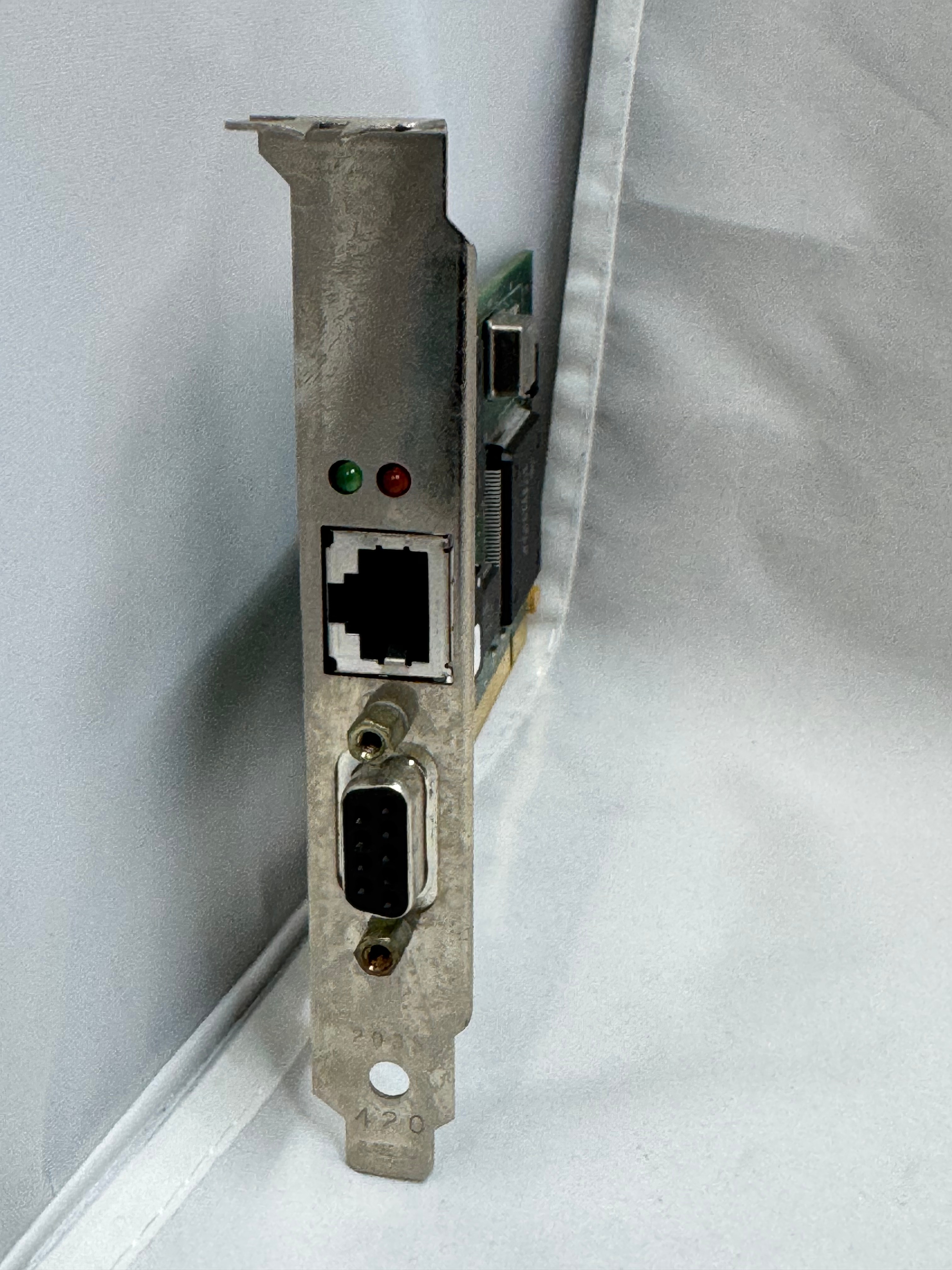
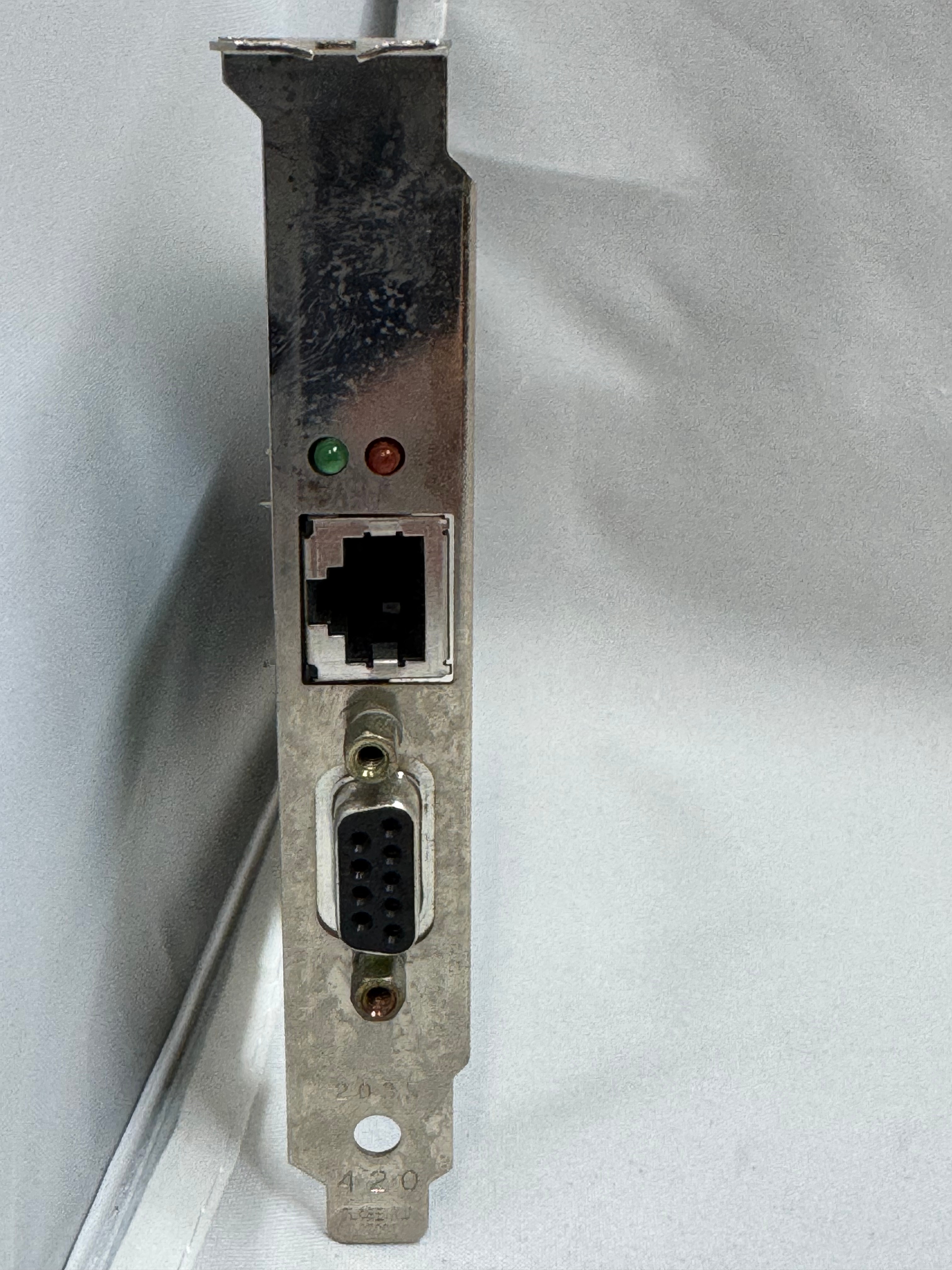
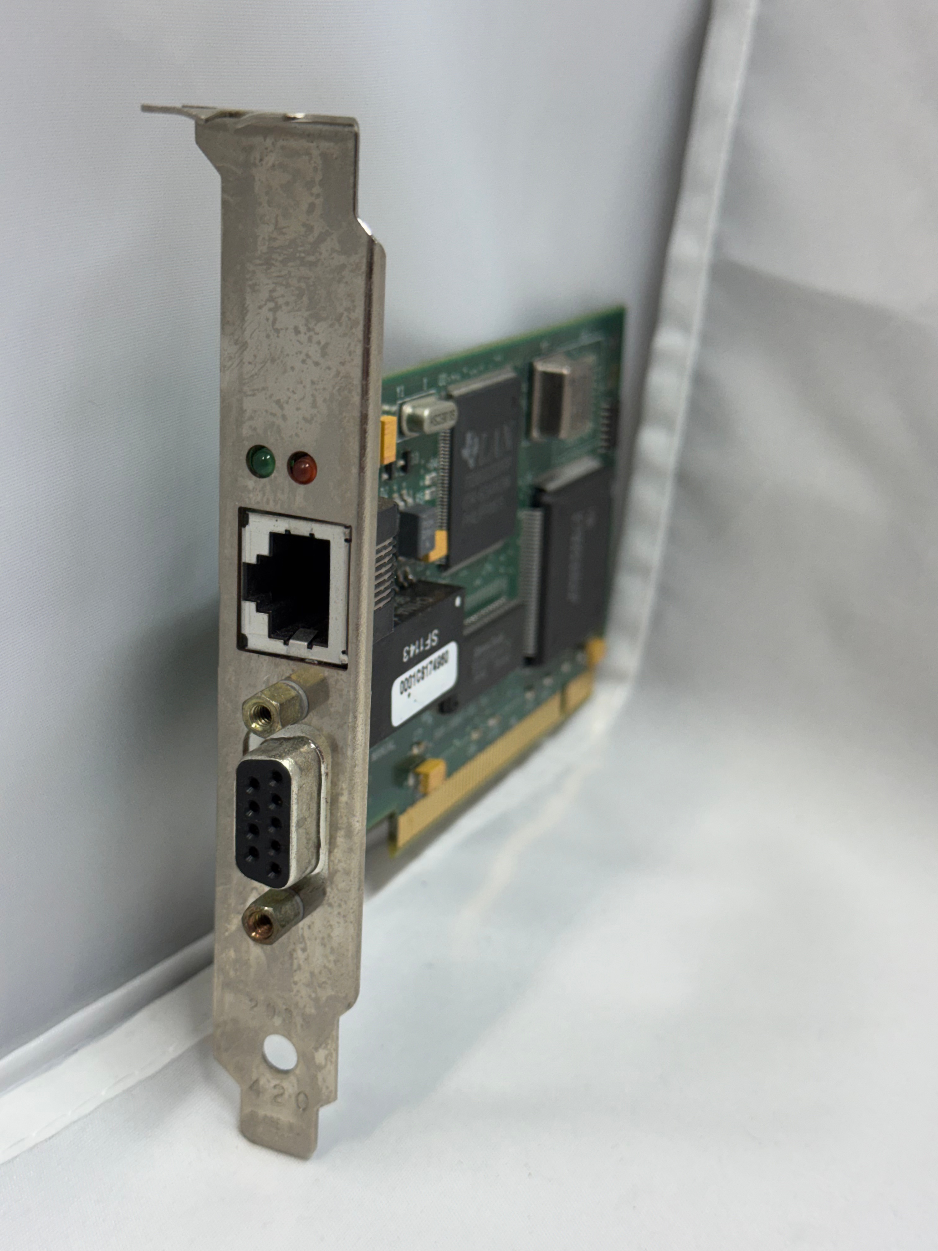
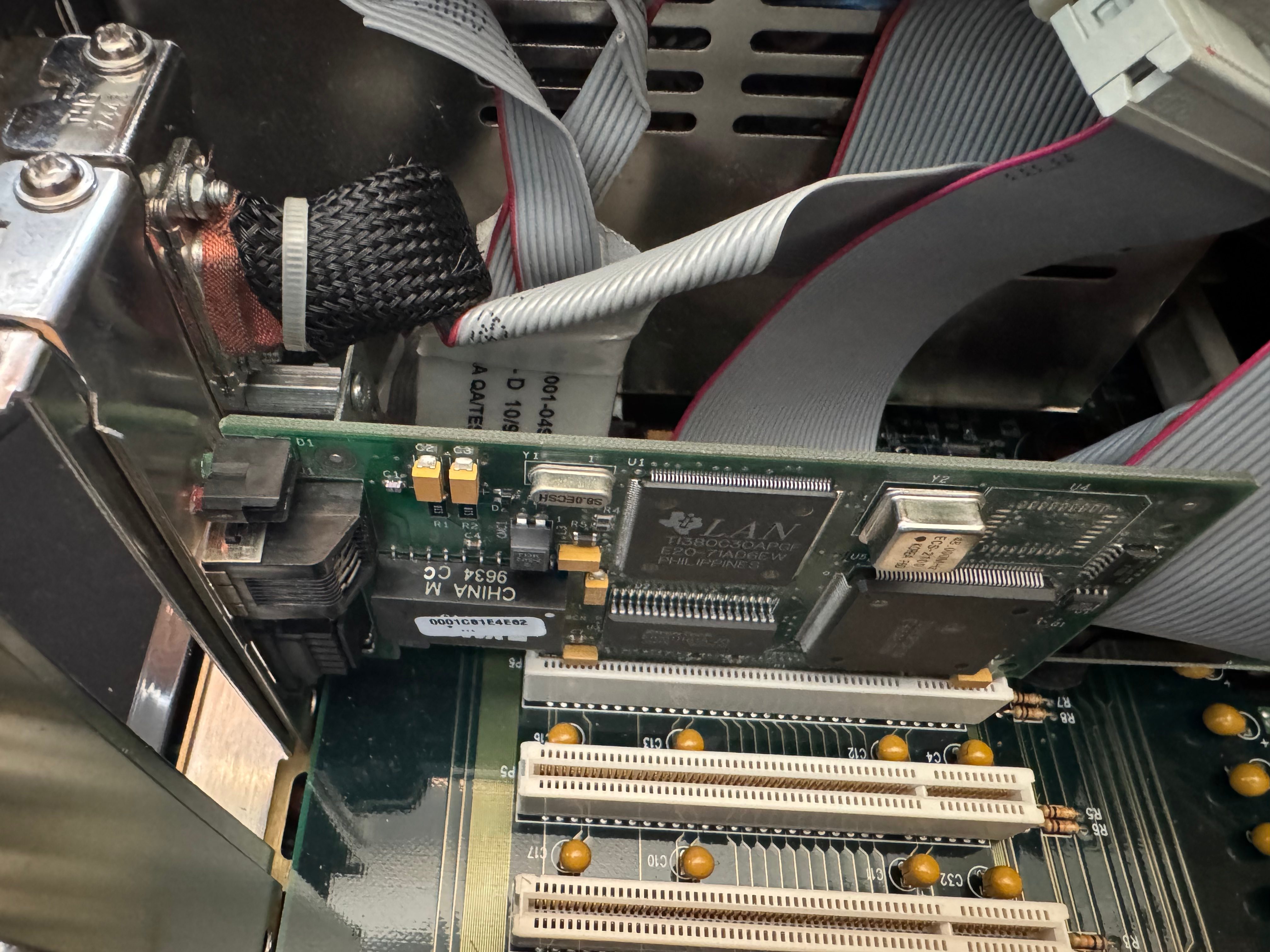
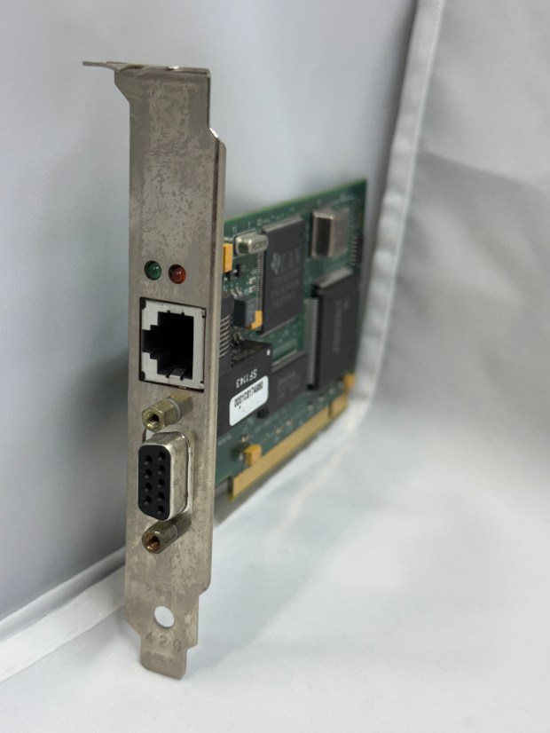
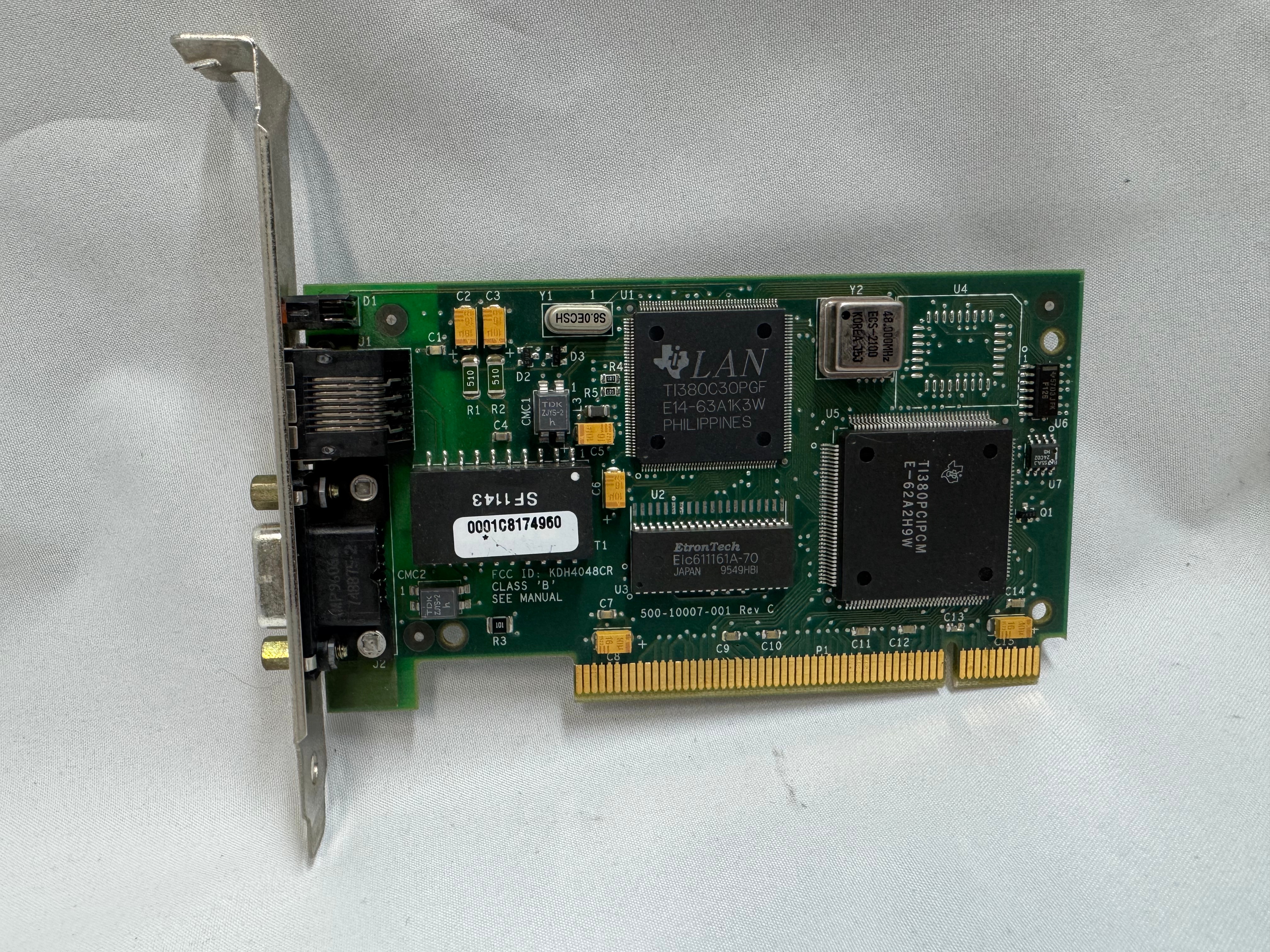
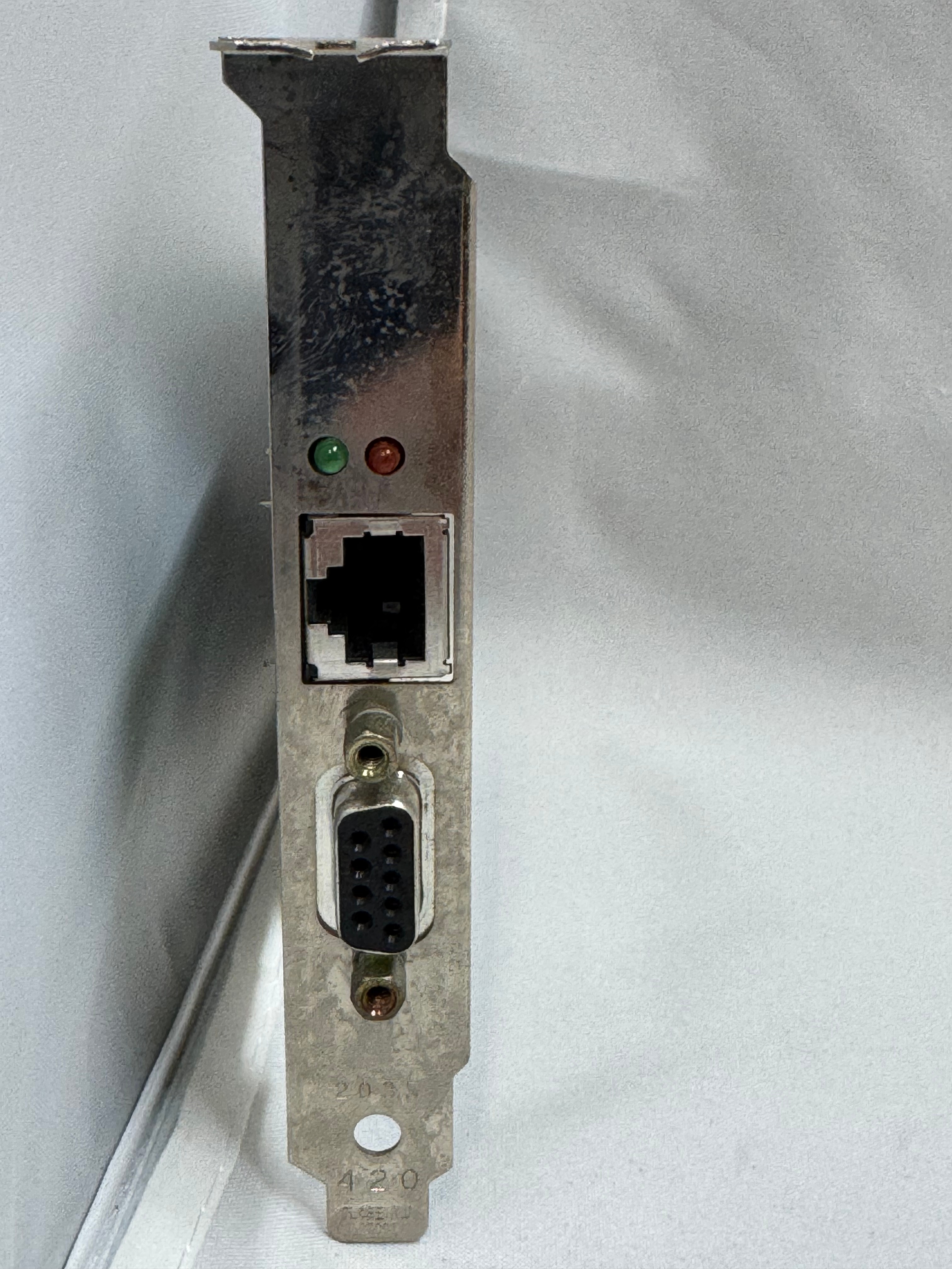
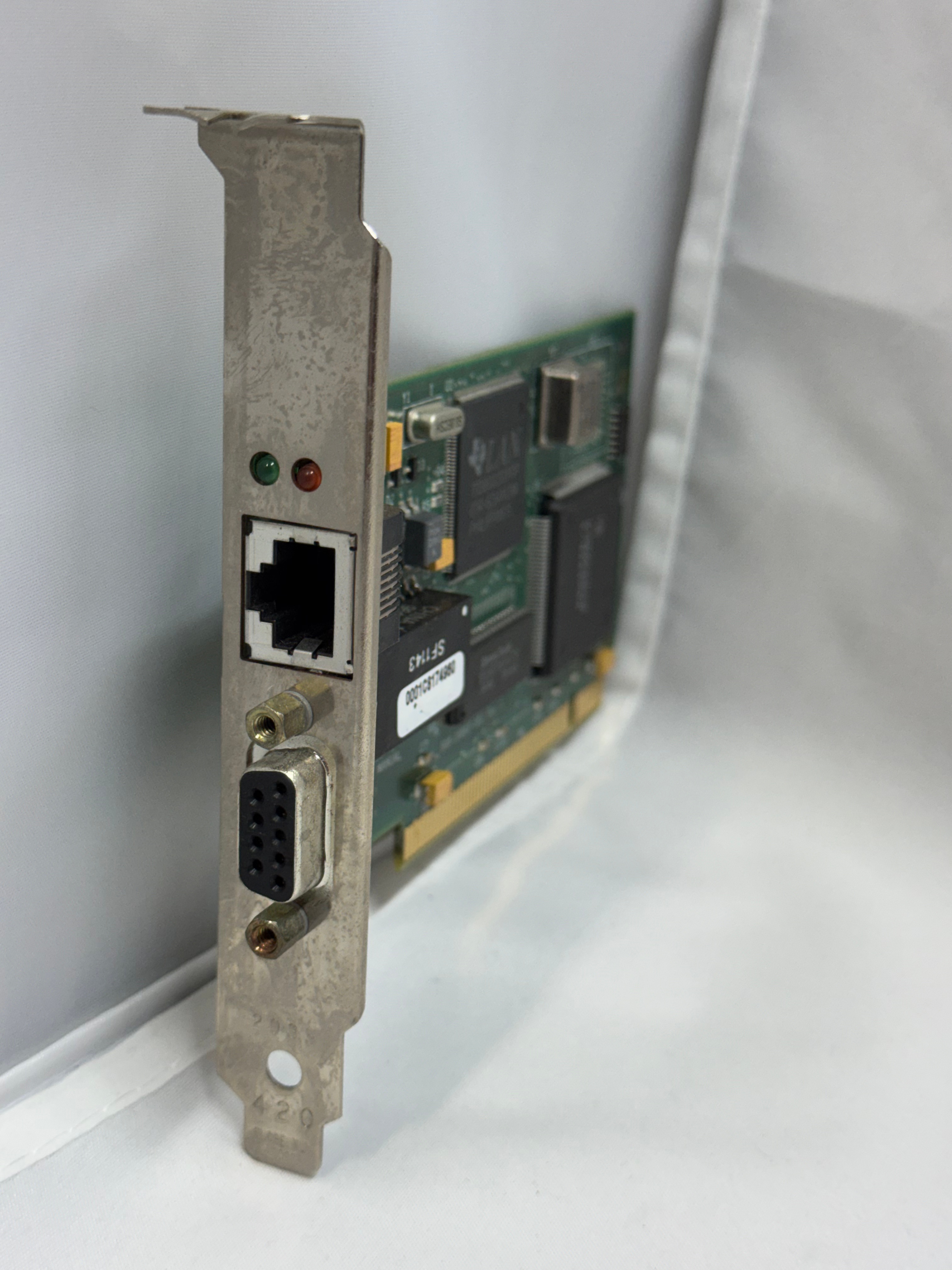
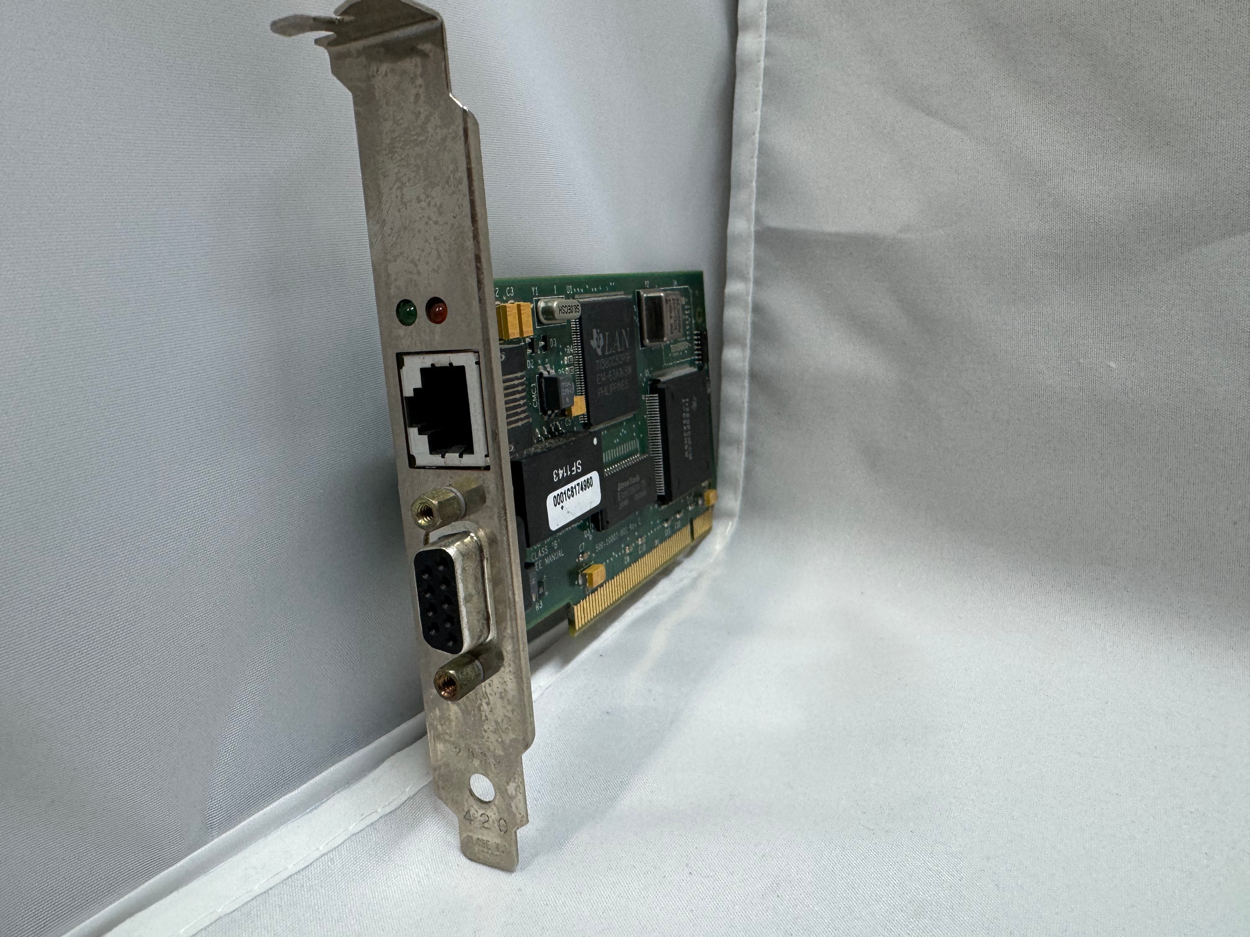
Last, but not least, I got a Thomas Conrad PCI Token Ring card for the system. It has 10/100Mb ethernet on the motherboard and in a breakout slot. But for the true retro rack road warrior, I needed the Token Ring to go with the rest of my Token Ring gear. There was one downside to this card, the same issue others have mentioned with Token Ring cards… The driver attempts to join the ring when the system boots; if it can’t, you get a 30-second or so delay, then an error message. Every. Boot. But that’s the price to be awesome and have Token Ring.

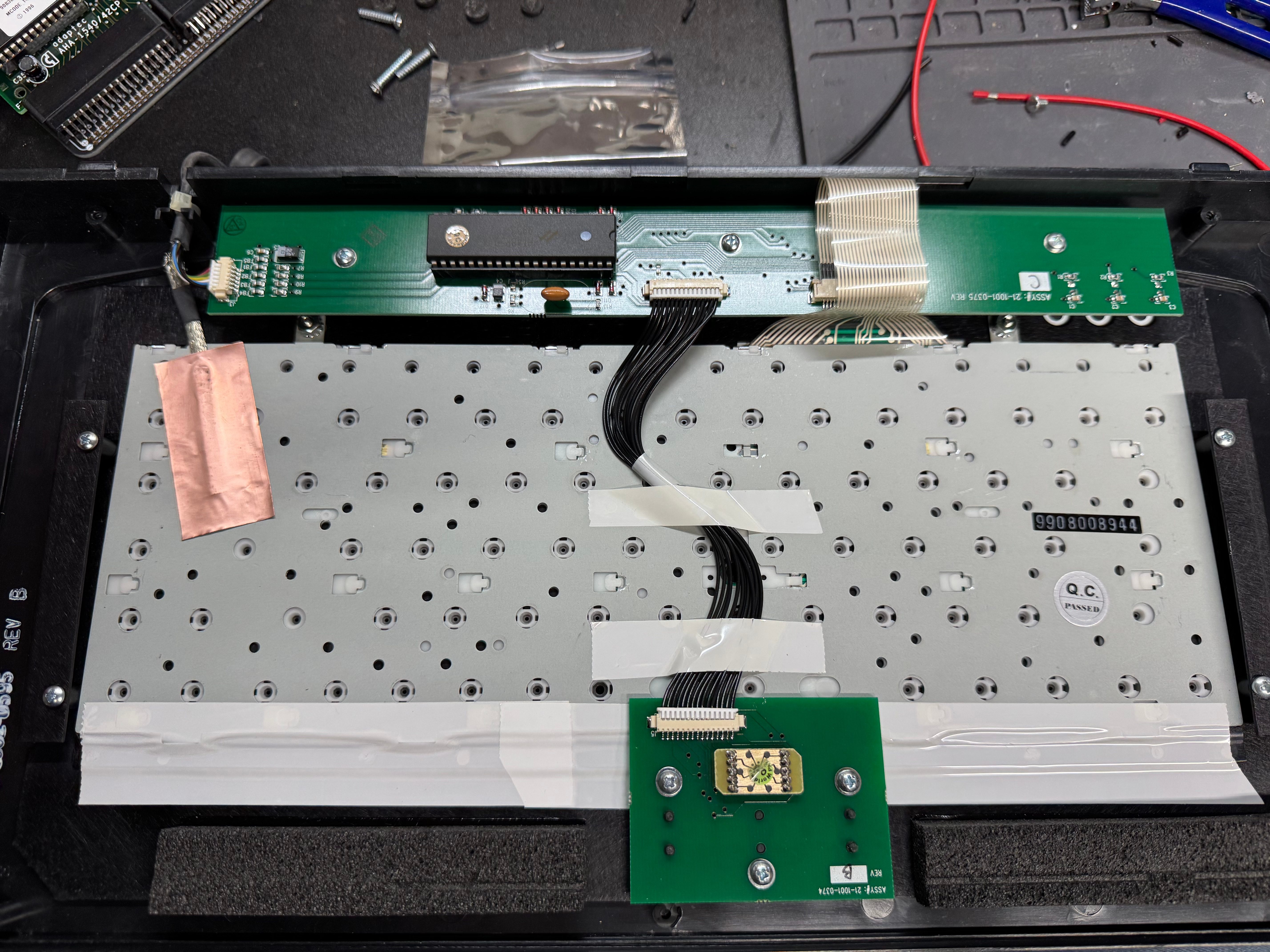
I had been using the system for a little while, and the keyboard had some sticking keys, so I took it apart and gave it a good cleaning. I think it still needs some work, but overall, it does what it needs to do. I can always use a USB keyboard now.

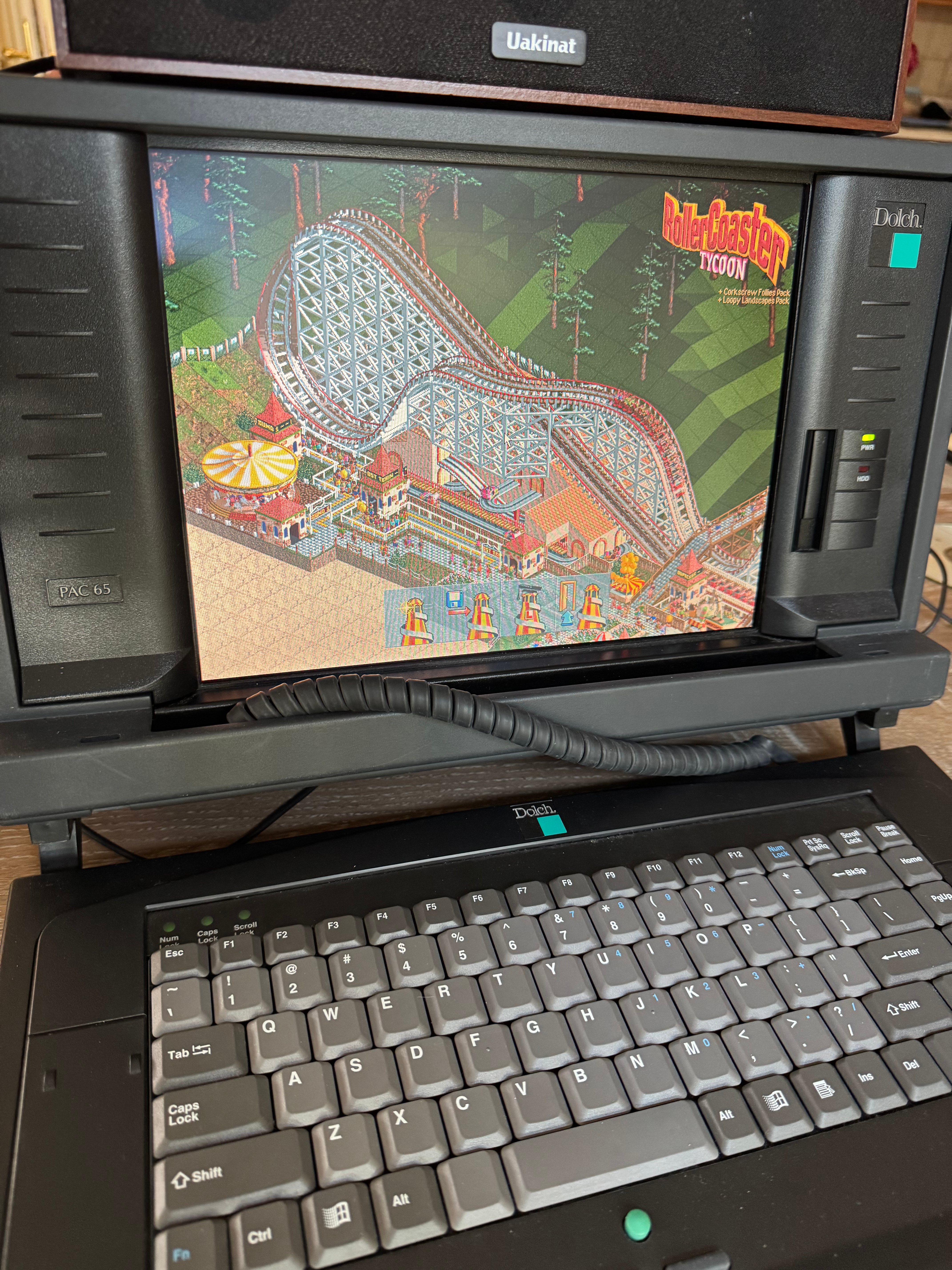
It’s a fun machine, I’m glad I got it. The nice part about portable systems is I can fold it up and put it in the corner. It’s my new go-to retro system. When I want it, I just pick it up, plug in a power cable, and I am back in business. There are some outstanding items: the power supply hasn’t been serviced and could explode at some point, the motherboard capacitors are 30 years old, and the ISA slot won’t recognize cards. We are going to ignore those for now and play RollerCoaster Tycoon instead!

ONB-Classic

Repo: https://github.com/palantir/onb-classic Docs: https://palantir.github.io/onb-classic/

Background

I have been on a slow mission to open source some of the projects I have worked on over the years. The next project after the IsoFileReader actually predates that other project. ONB-Classic has the ability to serve files directly from an ISO without extracting the ISO, to do this we utilize IsoFileReader. That feature required me to open source IsoFileReader first. ONB-Classic is a fork of the OpenNetBoot project I started around 12 years ago. The project originated with having to PXE (Preboot Execution Environment) boot systems via the network, and I wanted to be able to use Proxy-DHCP (more on that in a second) to boot anywhere no matter the infrastructure. This allowed any sysadmin to pop up a PXE server, quickly image systems, and then tear it down.

When I started this project we were imaging Windows 7 machines with Symantec Ghost (what a time to be alive). It wasn’t new at that time, but it had a built in utility from 3Com which allowed us to do Proxy-DHCP, and PXE boot systems. Proxy-DHCP is when you have an authoritative DHCP server giving out addresses on a layer 2 segment, but then have a secondary DHCP server which jumps in after the Server -> Client offer broadcast and offers up boot information (PXE data) which the client then combines to boot. This has its own RFC as part of DHCP, and works on all (with some difficulty) PXE roms.

Concept

The main concept of OpenNetBoot was to bring PXE, TFTP, and HTTP services together into a simple app, allowing someone to stand up an imaging system or Linux installation system anywhere. I also always hoped to open source it, hence the name. The program started as what you see in the repo. It became classic when I had the idea to make it into a web app, and that web app became more of a platform with plugins that could allow different types of system installation. That greater platform was more work specific and I may write about it later, but was very mission focused for building servers at work. It hooked into different systems like server ordering and customer delivery.

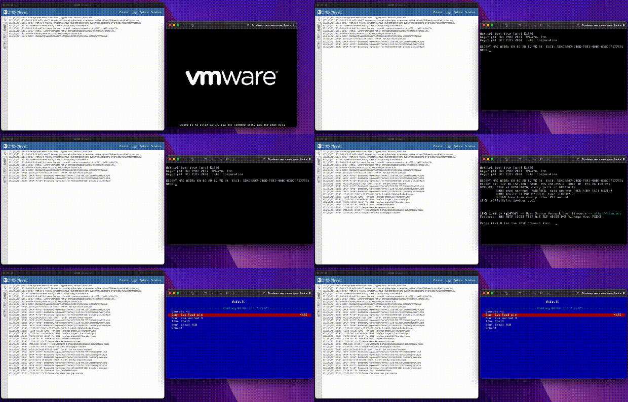
This project was where I really started loving lower level programming, and the things you could do if you owned the whole stack. This allows you to have greater insight into the boot process, in addition to doing some fun tricks with the protocols because we control them. I can send the client to different images depending on data I get at different stages in the pipeline, watching the client progress through the boot stages.

Development / Boot Flow

There were bumps along the way. The system would be able to boot one system, and then not work on the next. Some of this came down to vendors **cough** Realtek **cough**, not following the RFC and requiring extra bytes where there are not supposed to be any. We later moved from shipping all BIOS systems to UEFI, which proved to be a new generation of PXE roms that were more picky. The project was also written in Java, this allowed me to run it on any operating system, but this also led to issues where different systems would treat sending to a broadcast address (255.255.255.255) differently.

At this point it may be worth going through the boot flow, and how I always used ONB. A server boots, asks for DHCP, your local network gives you an IP and ONB comes in and gives boot information based on the headers in your original DHCP request. Are you x86? ARM? Are you a BIOS system, or UEFI? Then we return the address to a boot server (ourselves) and a file to load, usually iPXE.

I have been using iPXE for the whole life of this project, it’s a great boot rom except it never was SecureBoot signed, forcing us to disable SecureBoot for PXE operations. That is until recently! iPXE project after a decade got their rom signed by Microsoft! I have been very excited.

Now that iPXE’s address is given, the client reaches out over TFTP to the server to pull the rom. TFTP is very slow; the client requests bytes of a file over UDP, we send bytes, the client acknowledges and requests next bytes. There is no windowing, and if the link is full because let’s say 100 servers are booting, some UDP packets are dropped, forcing a restart. That makes our goal to leave TFTP as quickly as we can. Once iPXE is loaded, it does a new DHCP request, and gets Proxy DHCP information again, but this time with an iPXE system id. Now we serve them a menu file instead of a boot rom. From now on, we can send them data in HTTP format, which is much, much faster and unlocks things like loading large kernel roms before the heat death of the universe. Loading 100MB Linux kernels at 500kb/s is not feasible for a production environment.

As mentioned, the application is written in Java, this allows it to load anywhere, and the JavaFX UI to work on any of them. Over the years things have changed; JavaFX used to be included in Oracle Java, and as we all moved to open source Java it became its own package. The application back end became heavily multi-threaded with threads dispatched when clients connect. Multi-threading dispatch allows the DHCP and TFTP servers to handle 100+ clients at a time. When a client reaches out, we get their request, and pass it to a new worker thread to respond. Then we can immediately free up the original server process to handle the next client. There are several core threads and the goal is always to get work off them as quickly as possible and hand it to a sub-worker.

I have gone on to update this application, and write other ones using JavaFX. It’s another one of those – devil you know – situations, where I do not love programming in it, but I know how it works. The SceneBuilder allows you to create the XML GUI templates fairly easily. One of the more complicated parts of the application is actually the logging system. It has to be able to pass log messages to the GUI, or the CLI; and then pass some of them to a text log file. This system also has to take logs from different threads as they fire, and try not to block. It naturally grew over time, and has shown to work well.

While I was deep in the protocols, I went off on a weird tangent: I added a ‘virtual NIC’ option to the command line of the app. It allows you to simulate a client on the network. It generates a new MAC address and reaches out to see how the authoritative DHCP server responds. That was fun because it was the first time I acted as the PXE client instead of server, simulating a full network card.

That is all ONB-Classic does. Brings those different parts together to help iPXE get through the process. You load your own menu and images to boot whatever systems you have. The application supports running as a console app, a daemon, or a full GUI app with a tray icon. It works on Windows, Mac, and Linux; over the years has been in production on all three.

UI Design

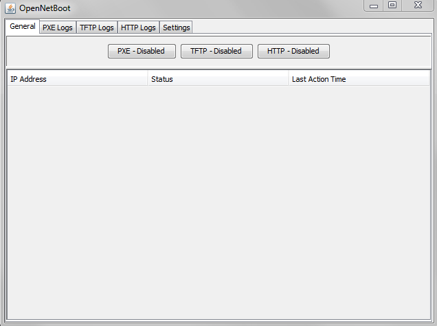
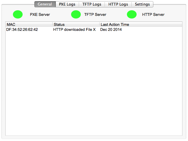
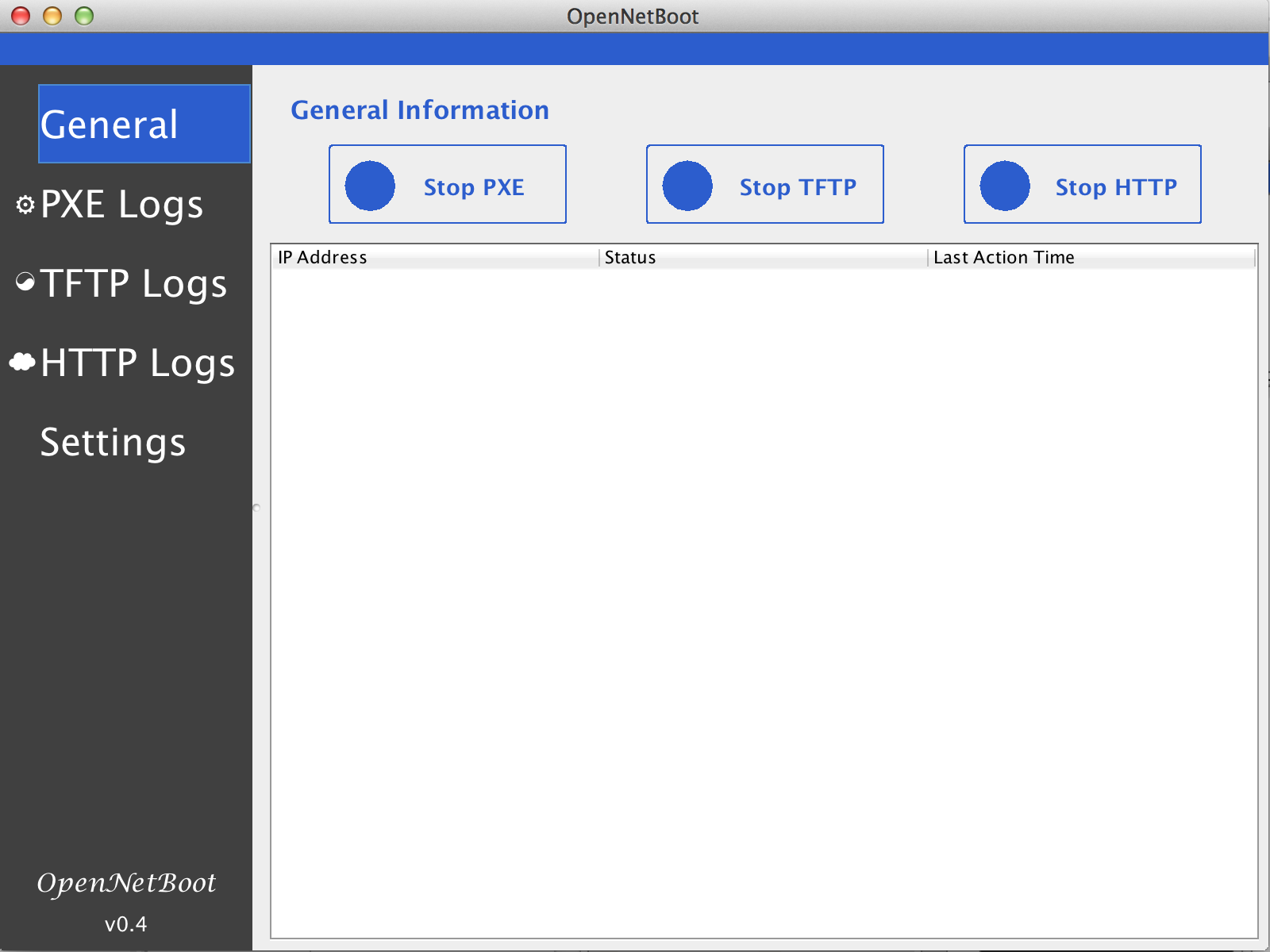
The app went through several designs and mock-ups. Not altering too much until it became a web platform.

I also tried making different logos. This is before generative AI, I had to sit there in Gimp or Inkscape myself and draw ideas. Here are a few for fun.

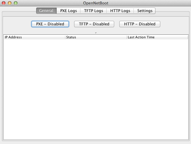
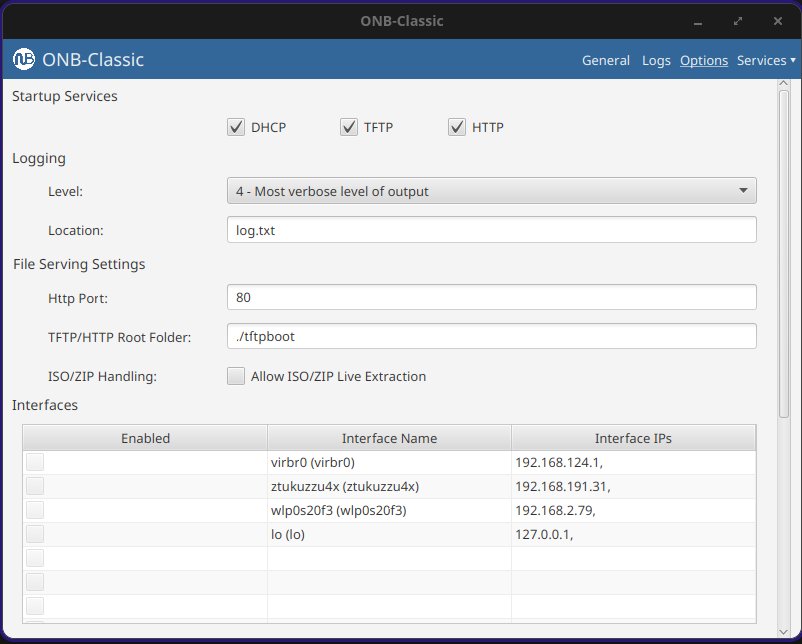
ONB-Classic Settings Page
ONB-Classic Final App Settings page and look

Wrapping Up

I have maintained this app for over a decade now. It ran the heart of our server shipments for years, shipping thousands of servers. It helped launch my career. And gave me a love of lower level programming down to RFC. I am excited to share it with the world, and I hope it helps a sysadmin out there to boot systems. The system is Apache 2.0 licensed, and I am always happy to get pull requests or feedback!

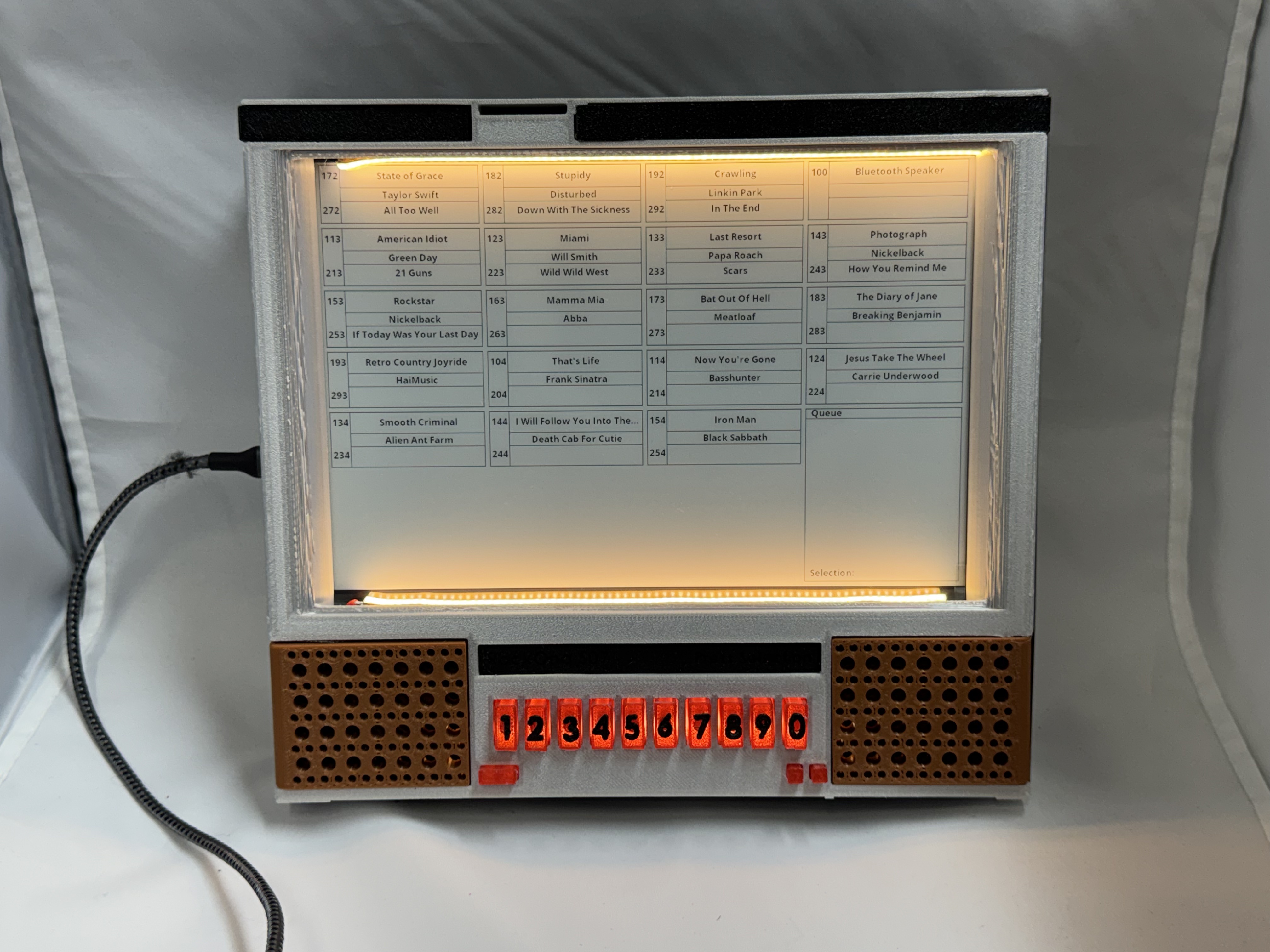
Rock-Ona 507

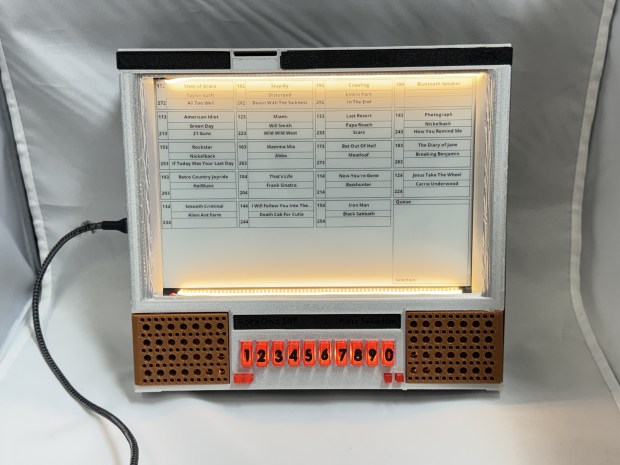
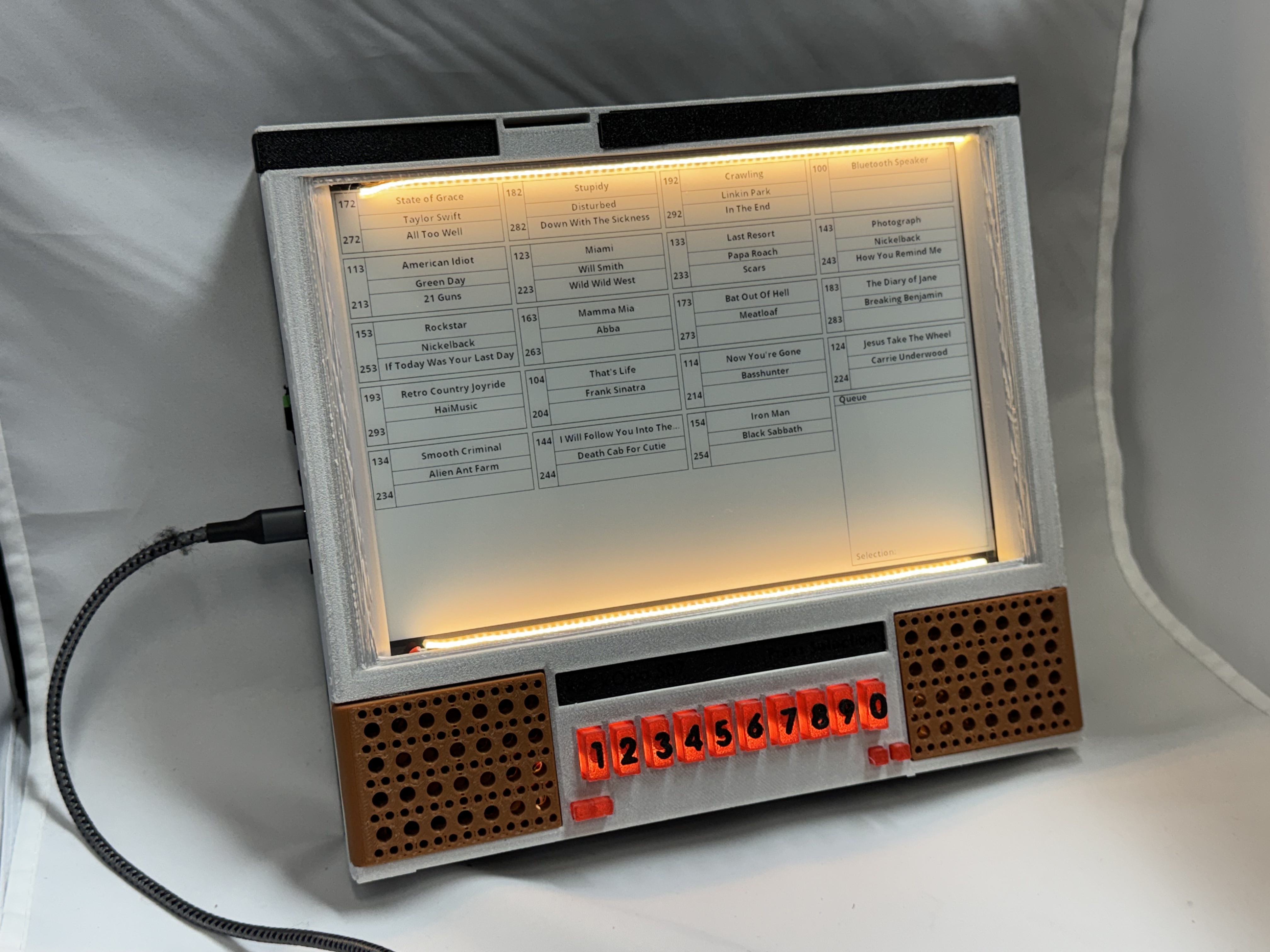
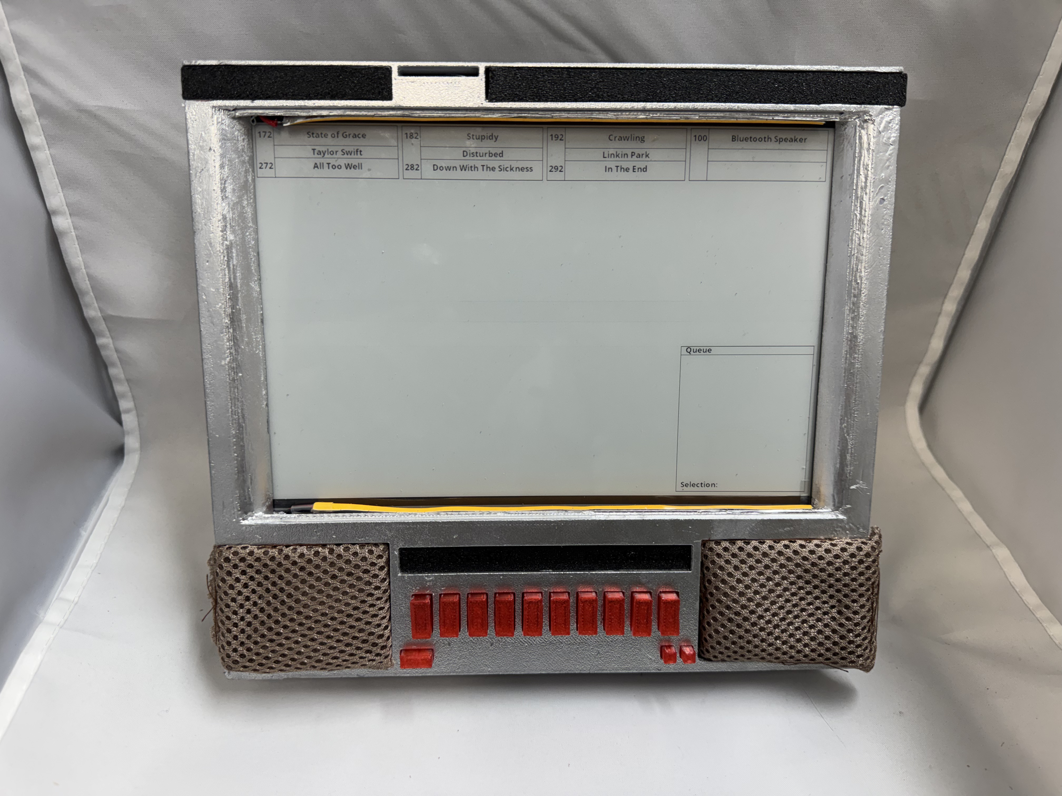
I have always loved audio as a medium, I don’t know why. Starting with playing around with an old stack stereo growing up; learning I can record a record onto a tape blew my young mind. I have done several projects around audio. Continuing on that, I love the classic Jukeboxes. They come from an era before microprocessors. Before you could just put a chip in something. When real mechanical and electrical engineering made things work. To pay homage to that I have been working on a similar looking device to an old Rock-Ola 507, but… I just put a microprocessor in it…

All 3D Models and ESP32 code is on Github.

Design

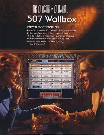
The Rock-Ola 507 was a table side music player for diners and restaurants. Rock-Ola had many models of “wallboxes” that connected to jukeboxes. I always liked the older 1548 models, but those have a lot of moving parts and many buttons. Instead, I opted for the simpler 507. I called mine the Rock-Ona 507.

The idea is you could walk up to it, see a list of songs, and type in the numbers to queue it up. I could have my favorite songs available, and then also have a Bluetooth option for when you just want to stream from your phone.

(Photo from Rock-Ola 507 wallbox jukebox flyer | #102562020)

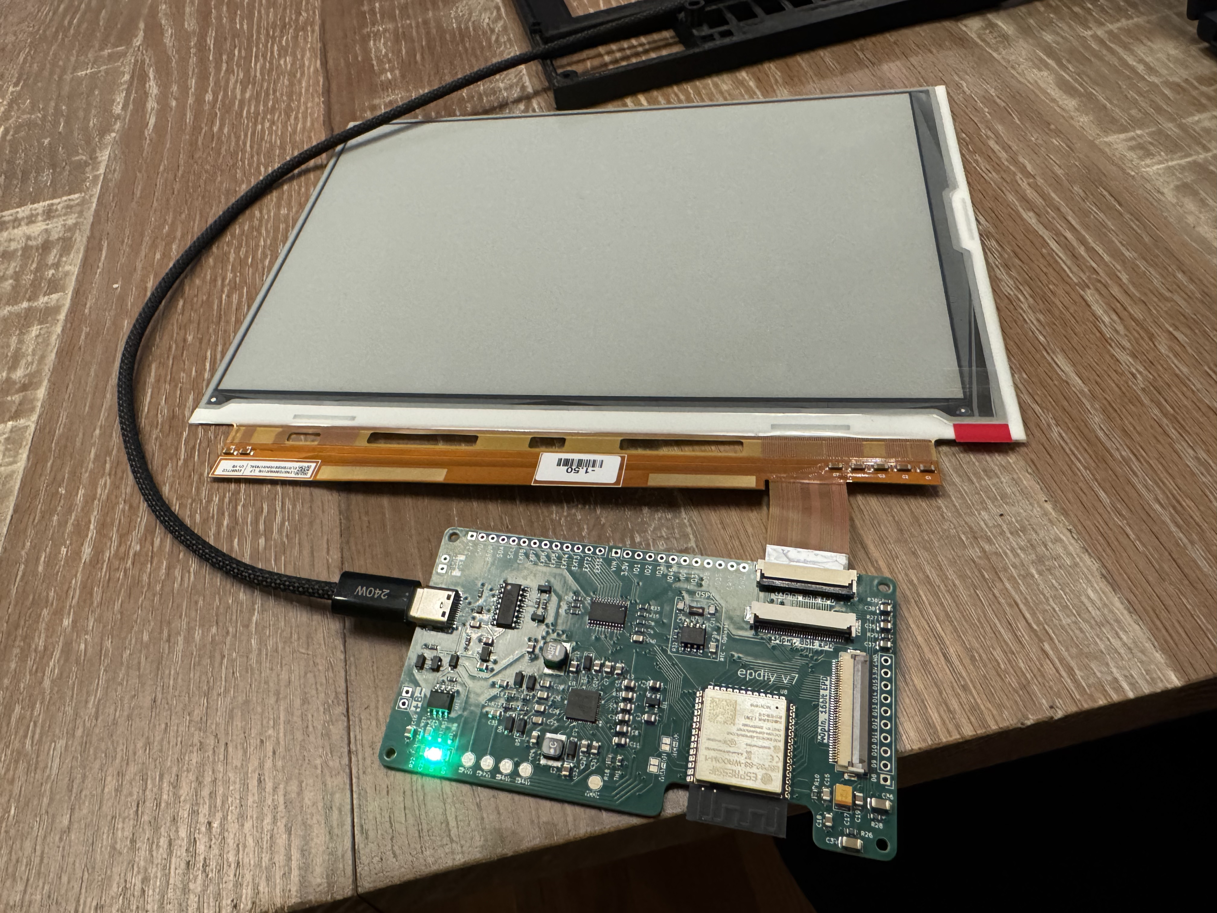
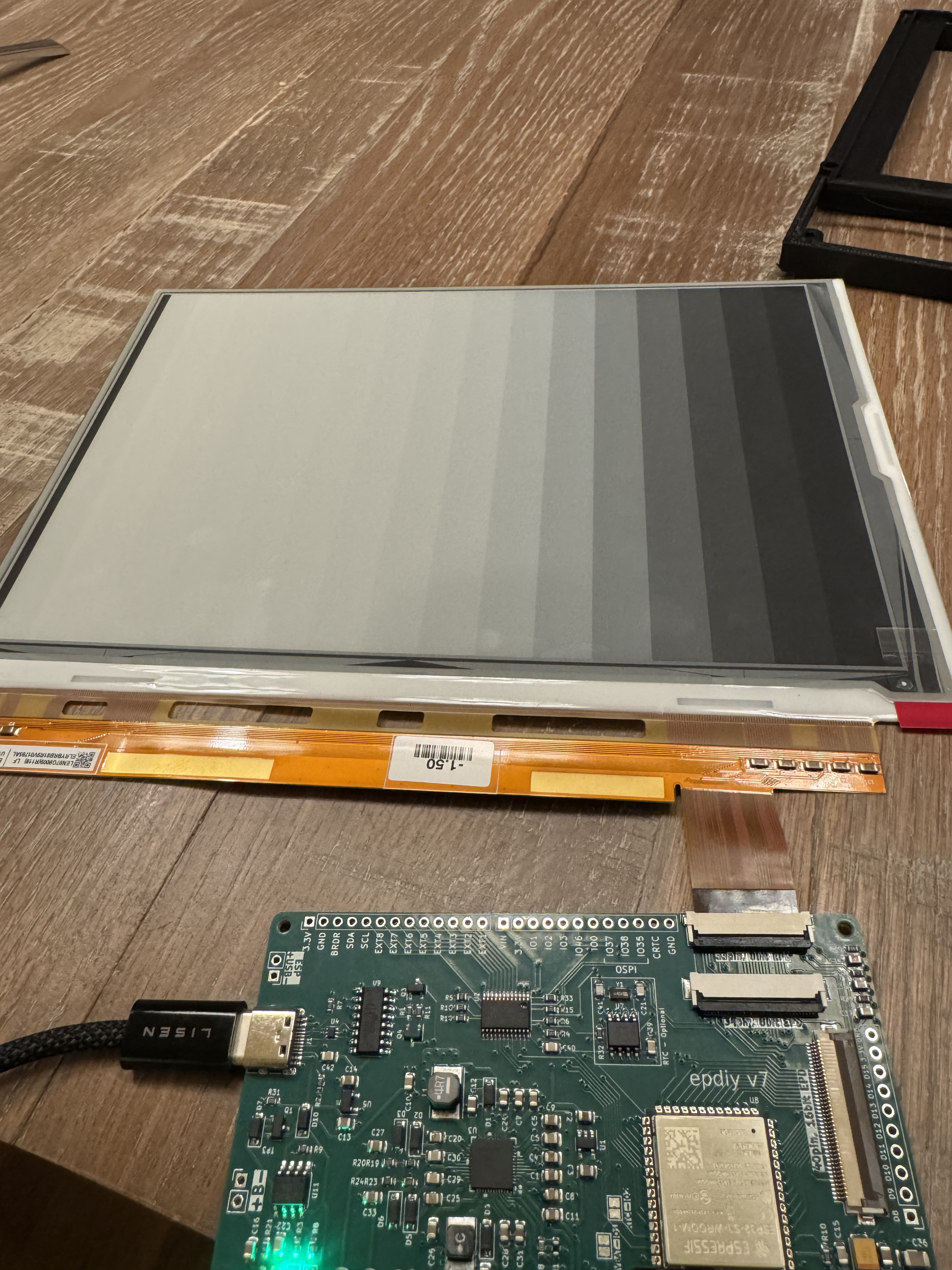
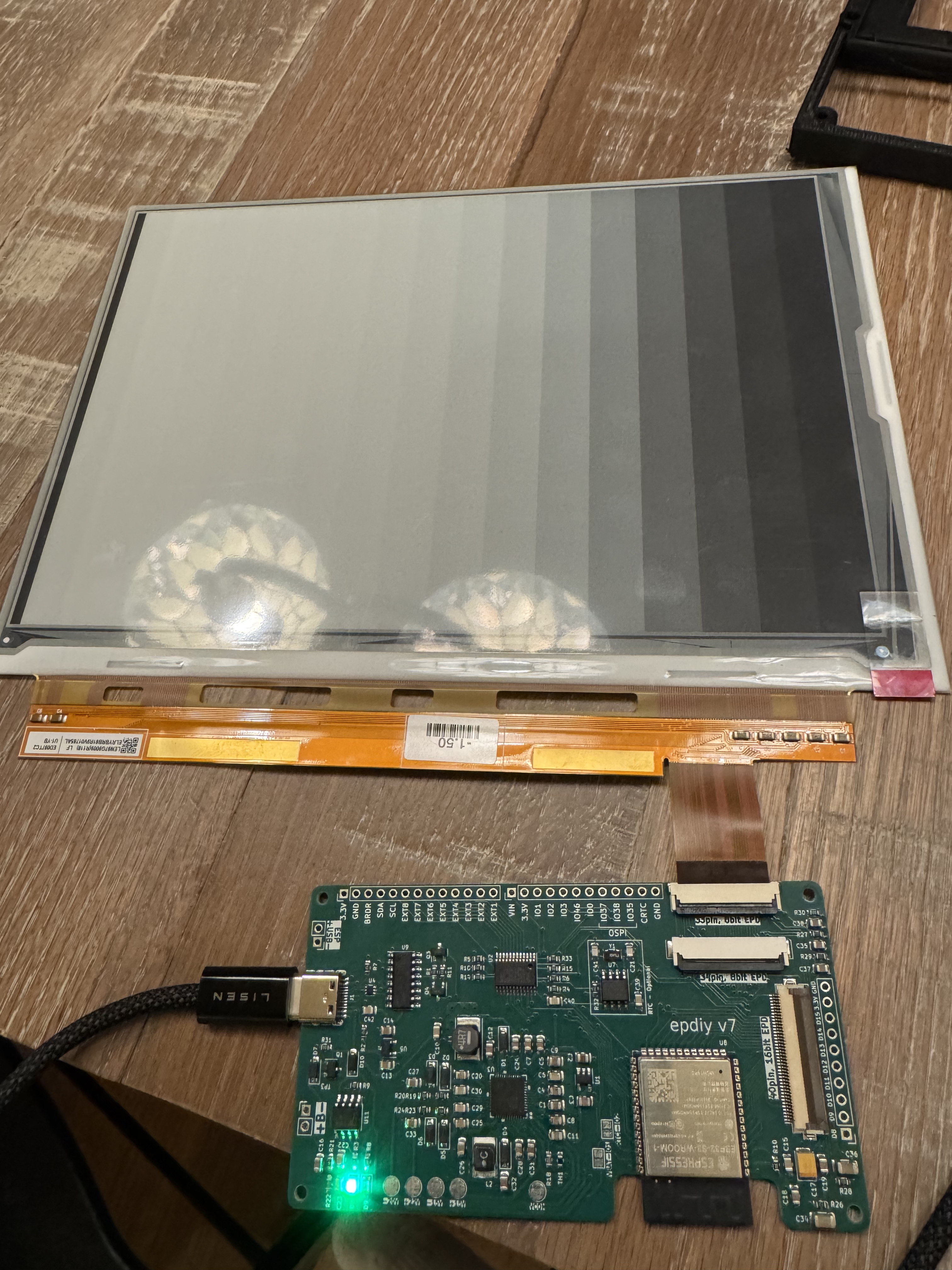
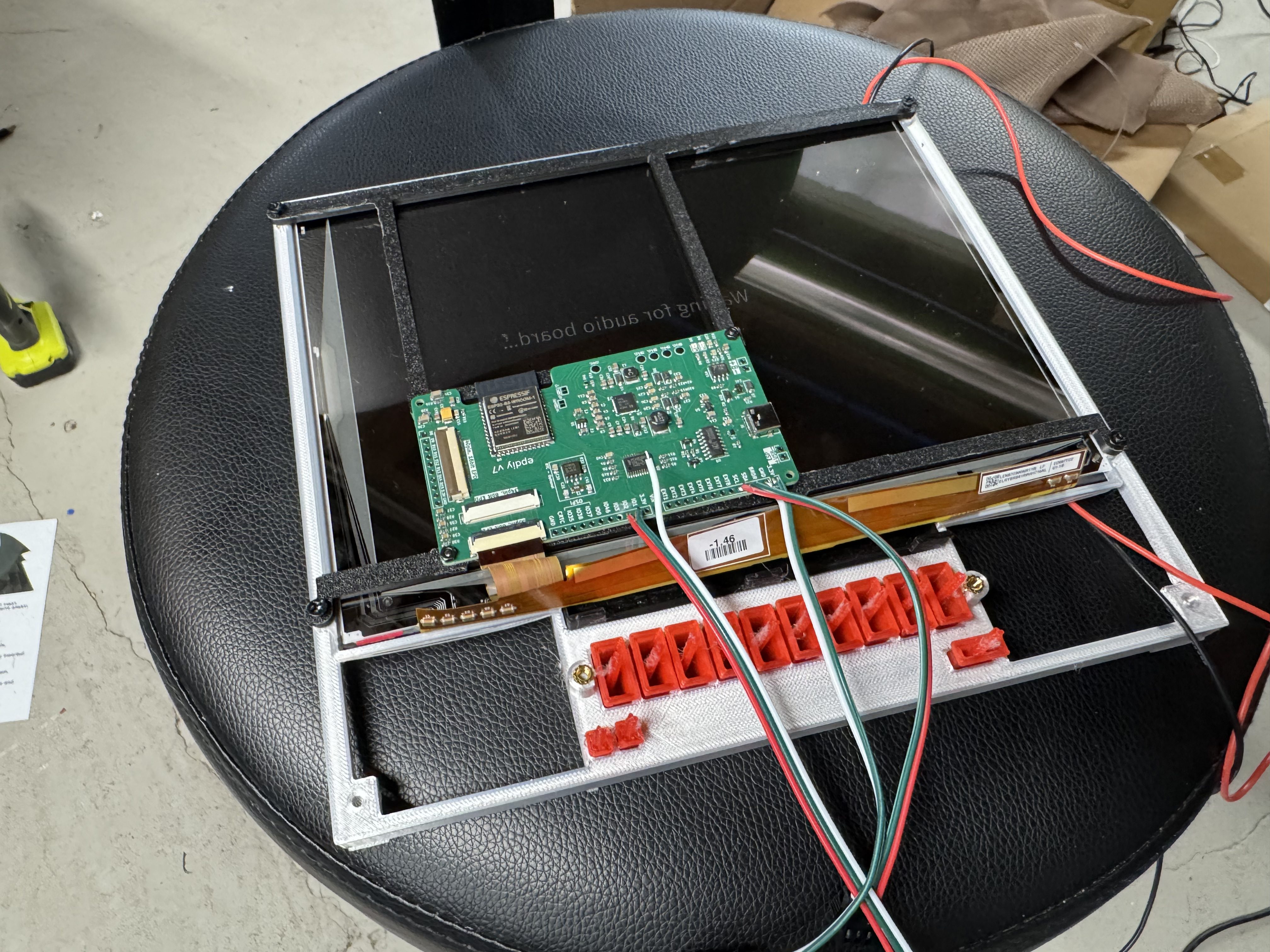
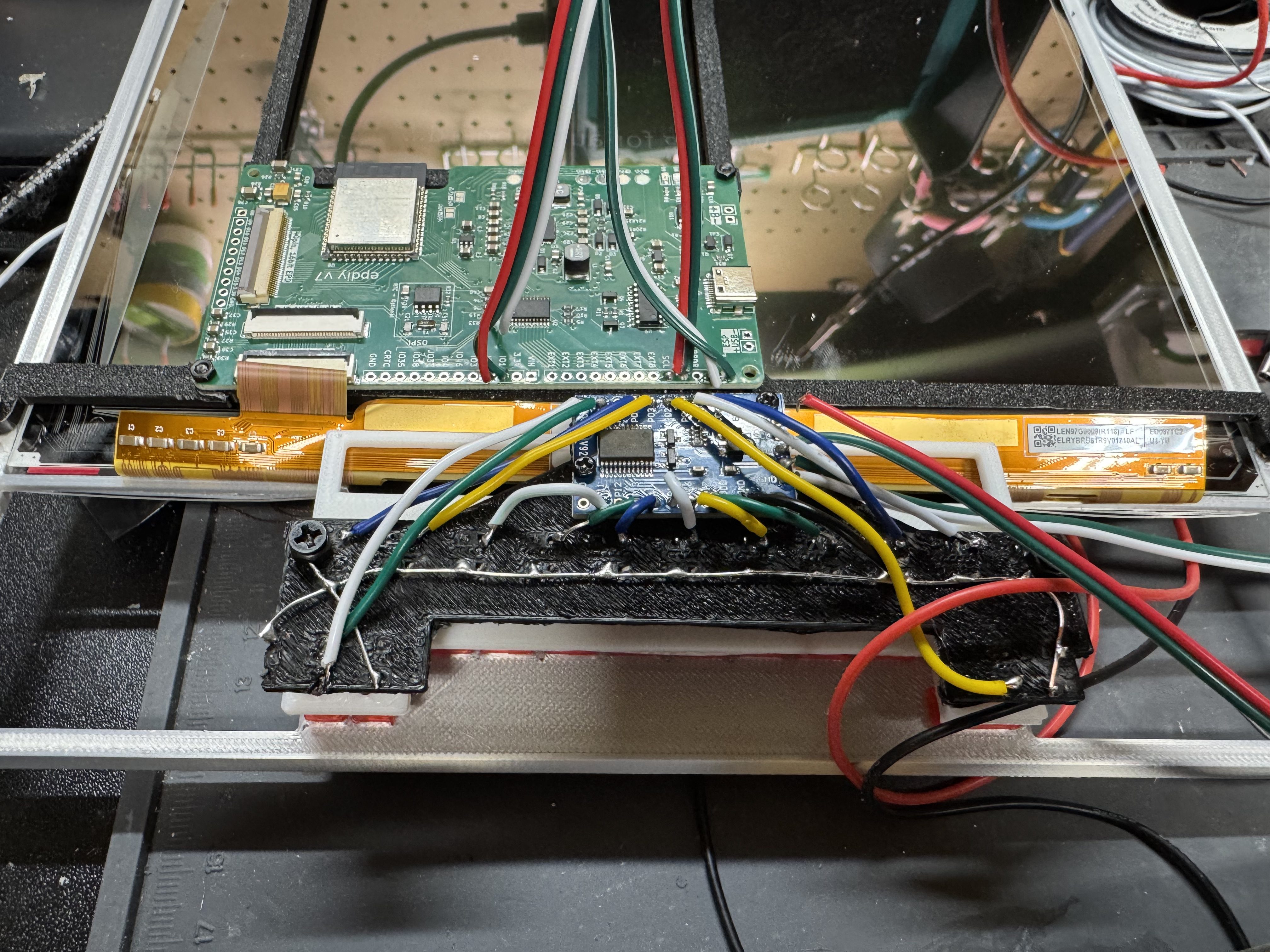
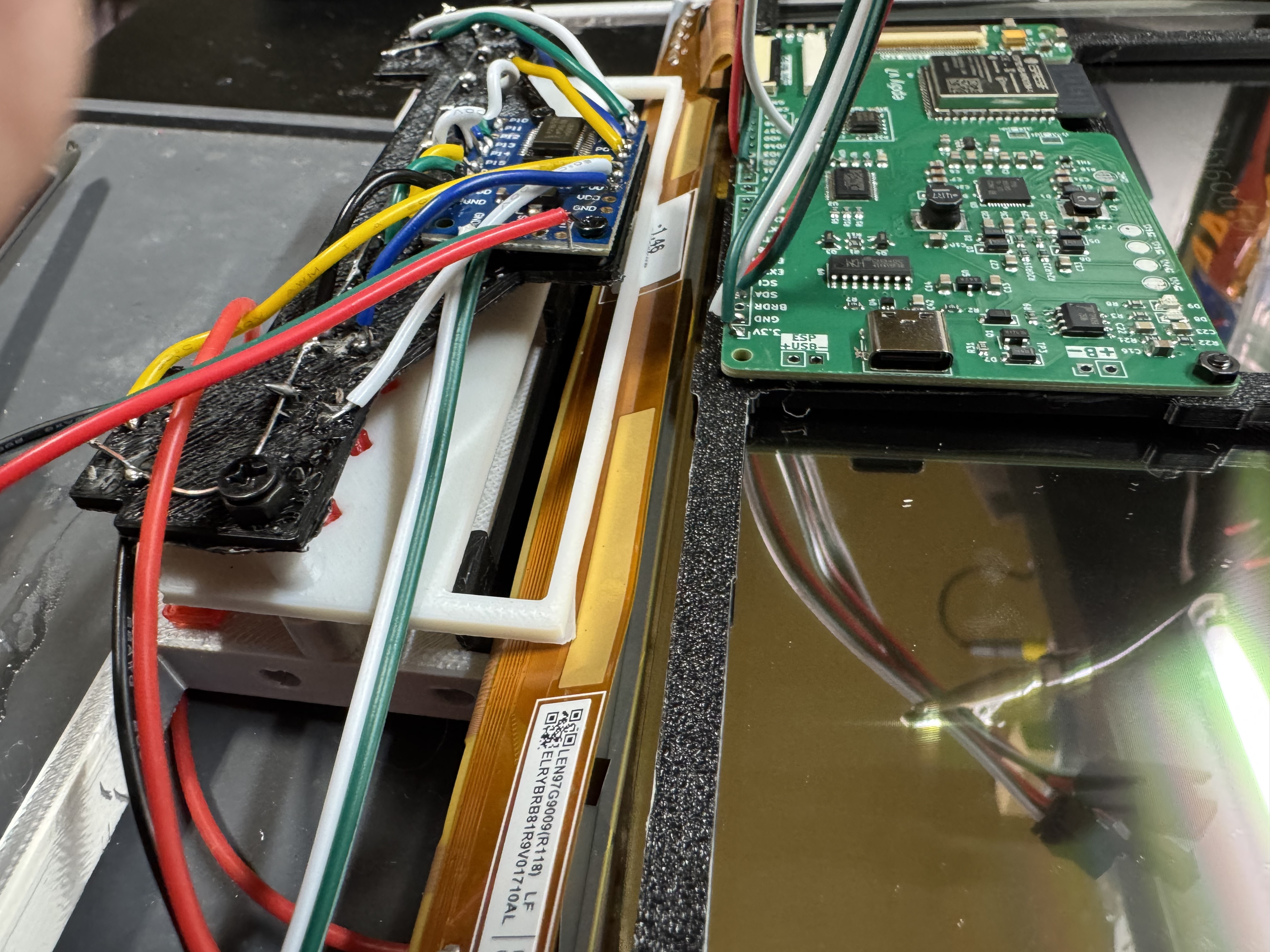
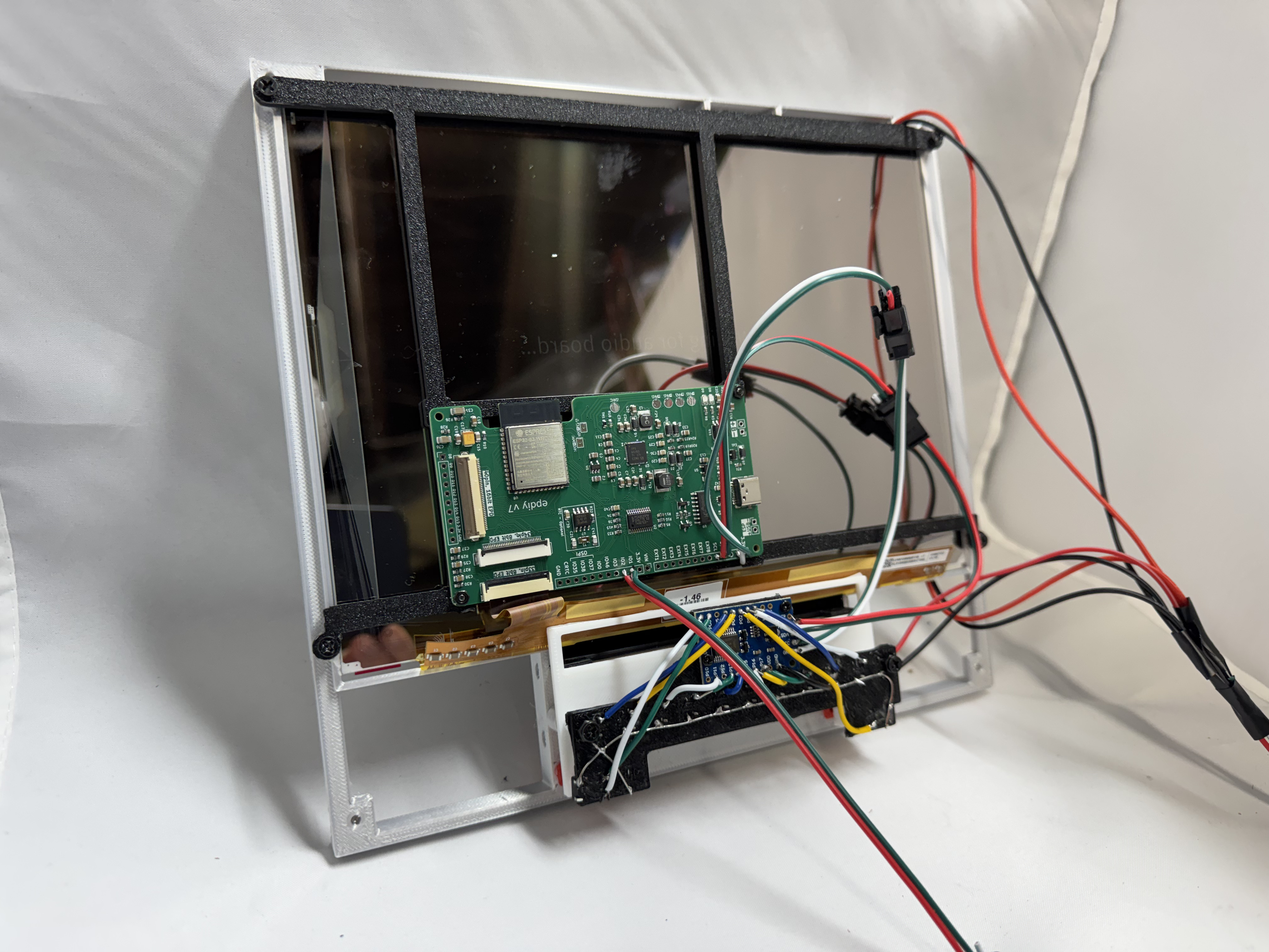
With this project I wanted to expand working with the ESP32 Audio board I did in the History Phone project. But also wanted a bit more of an old school vibe. To make the system feel more retro, one idea was to have the song list be an E-Ink screen. I thought that gave the system a softer feeling than an LCD screen. I have not used E-Ink in a project before; it turns out E-Ink panels need a special driver board. E-Ink is also not cheap, a 9.7″ panel will be $70, then you need the driver board. There are not standard boards out there to do what I wanted to, then I found an awesome open-source project!

Circuit Board Ordering with PCBWay

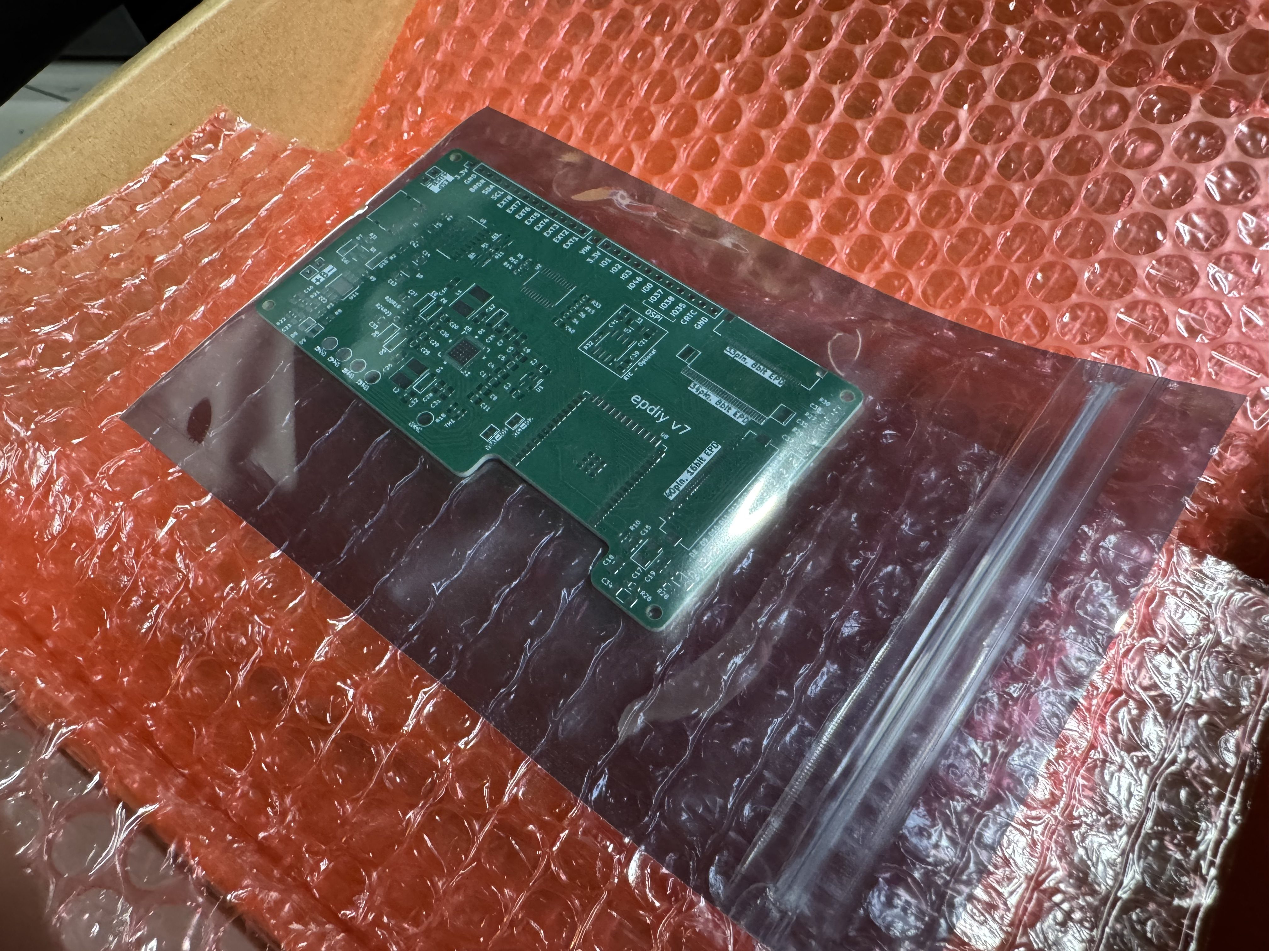
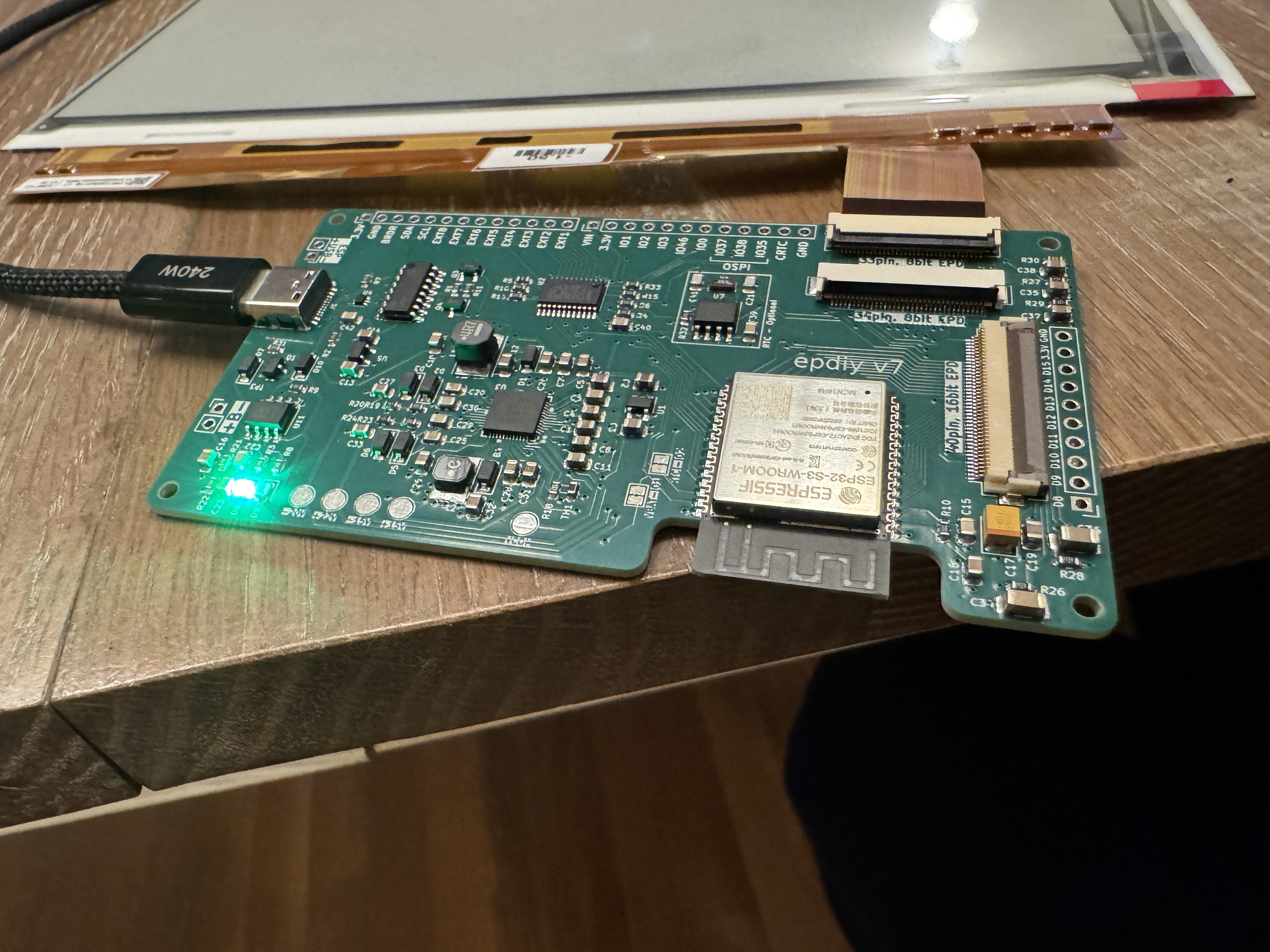
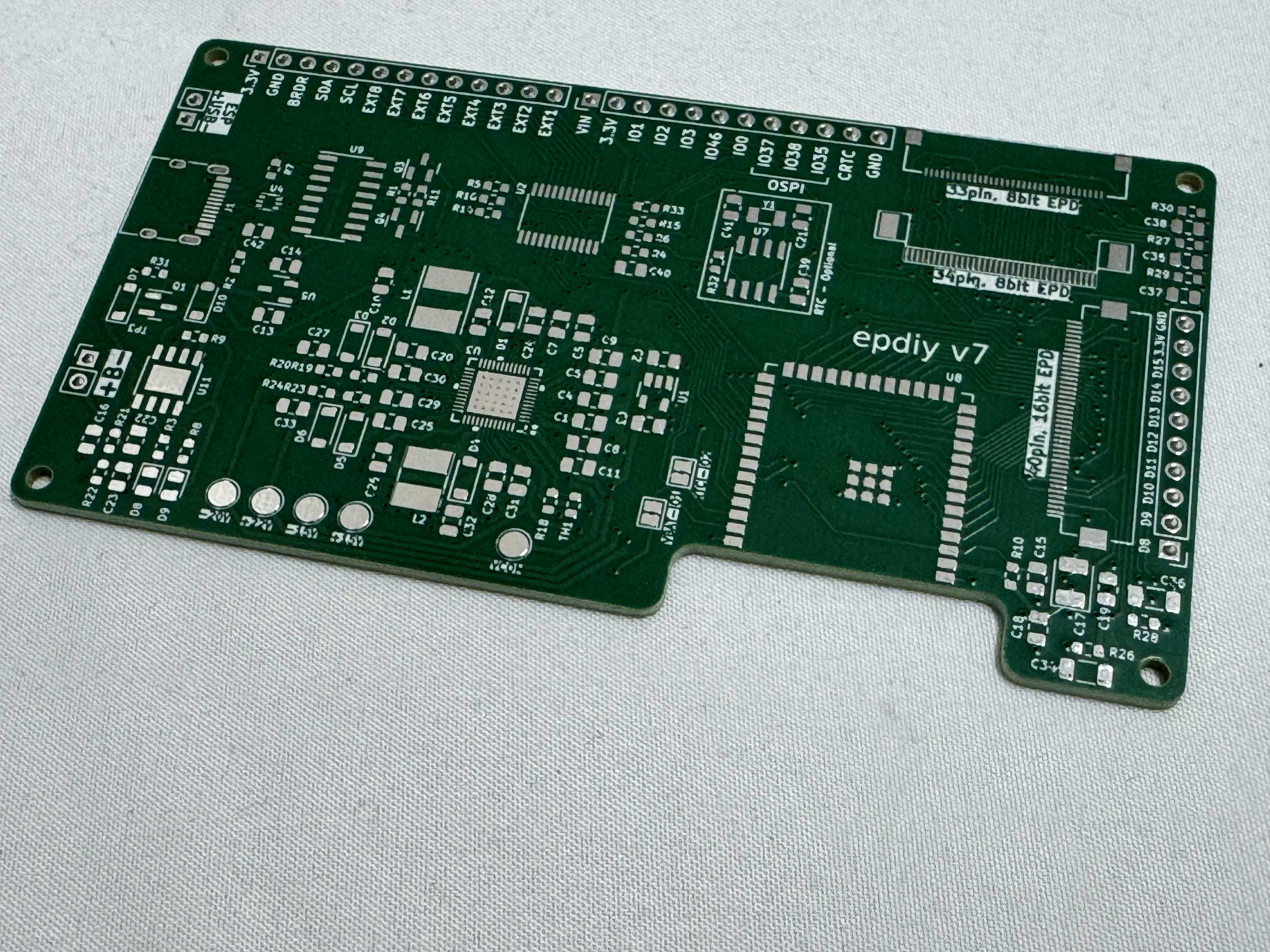
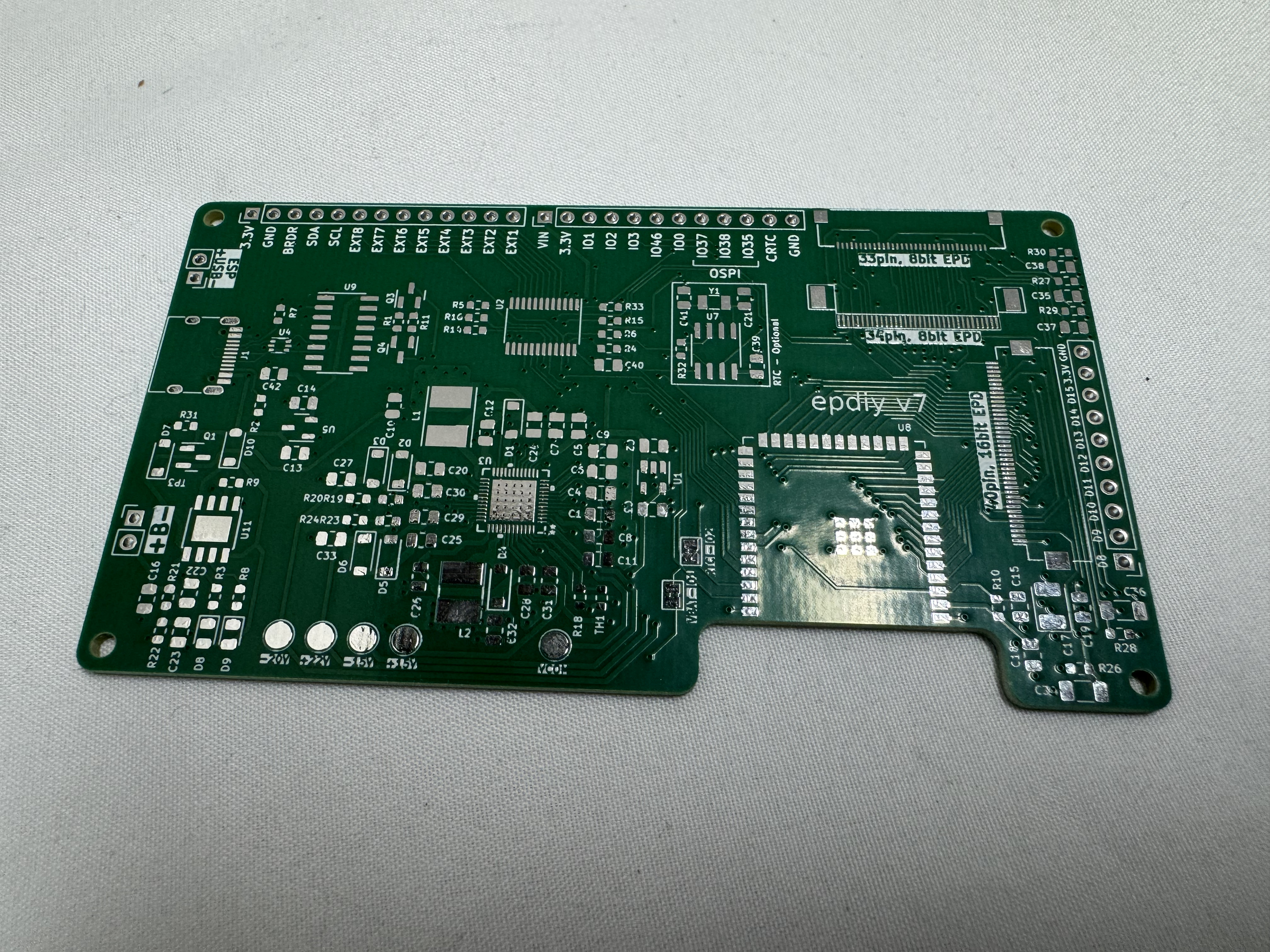
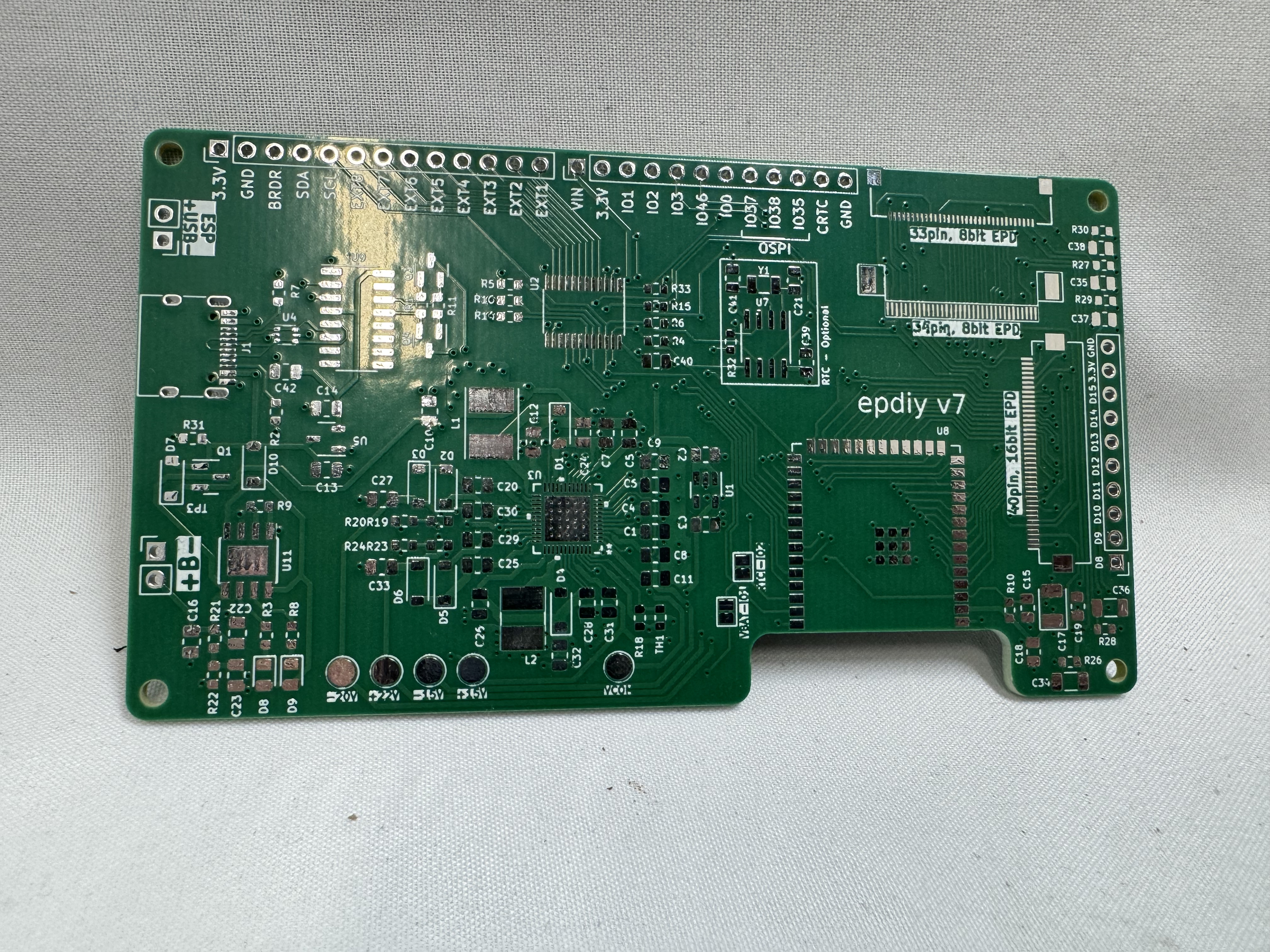
EPDiy (e-paper diy) is an open-source project on its 7th version of a universal E-Ink driver board! This introduced a new challenge for me; how do I get the boards made. I have not made circuit boards before, and while I have thought about making boards before, it seemed like an uphill battle. I had heard about PCBWay from Youtube videos and podcasts. I knew they had a shared projects area and hoped someone had done the heavy lifting here. Turns out someone had already uploaded the design and had it ready to go! I was not ready to push forward with the project yet and shelved the project for a bit. A few weeks later, PCBWay reached out after seeing the blog and asked if they could help pay for some of the boards to be made if I spoke about the process. It was a great match!

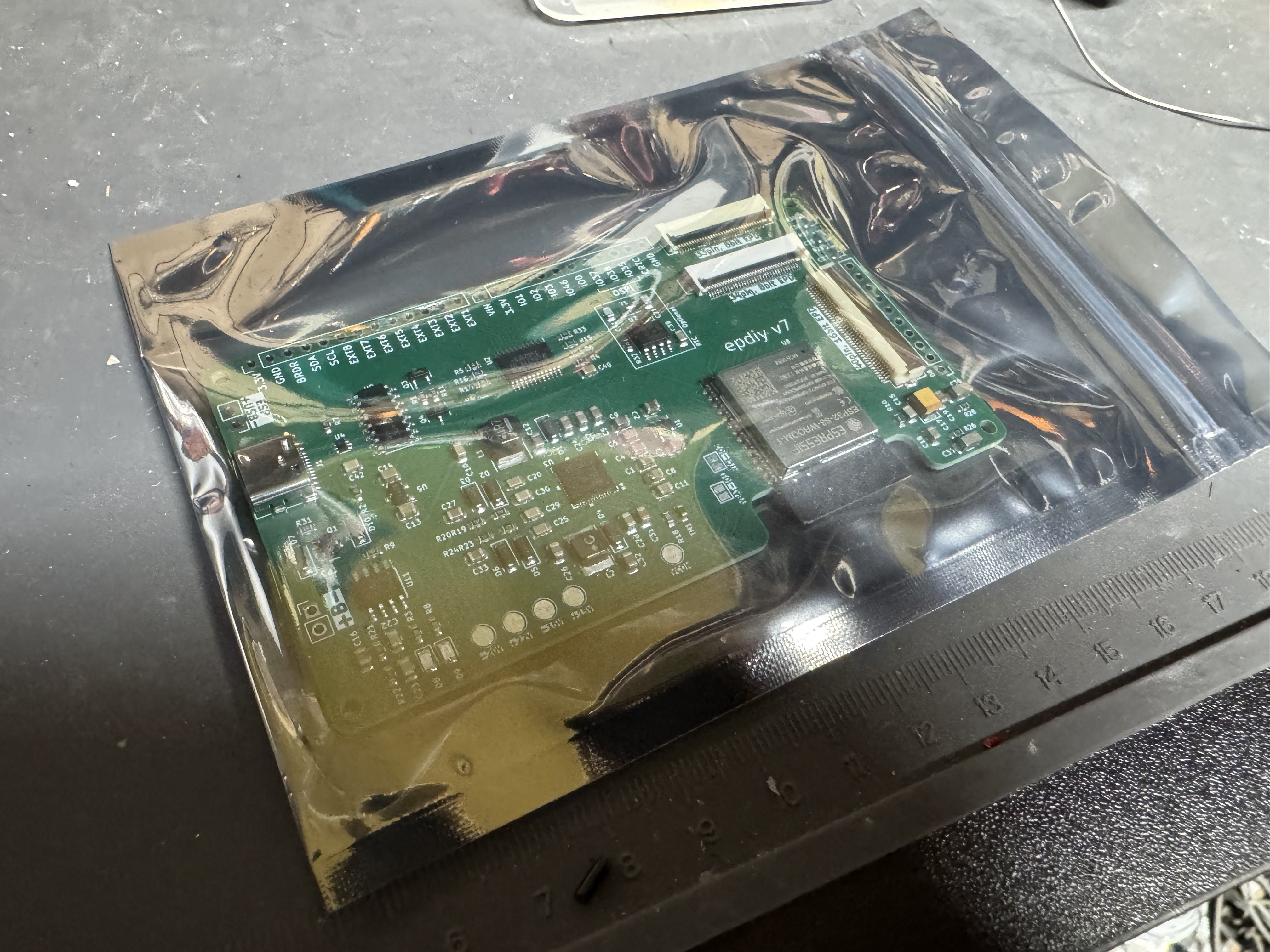
I went back to the shared project and added it to my cart. With the board needing a bunch of small capacitors and the ESP32 soldered to the board, I opted to also have them do full assembly. I submitted the order. A few hours later I got a message on the website and email. The shared project hadn’t set the PCB layer count, and I had accepted whatever was default (incorrect). I flagged https://vroland.github.io/epdiy-hardware/ as the source of the project and said I wasn’t sure how many layers it was. They came back quickly saying the board was a 4-layer board with 1oz for each copper layer, and it was resubmitted for approval. I was very glad someone who knew what they were doing was reviewing the board before sending it off. Later, I got another message from someone double checking the polarity of a LED on the board, and I was able to look up from the design and verify it with them.

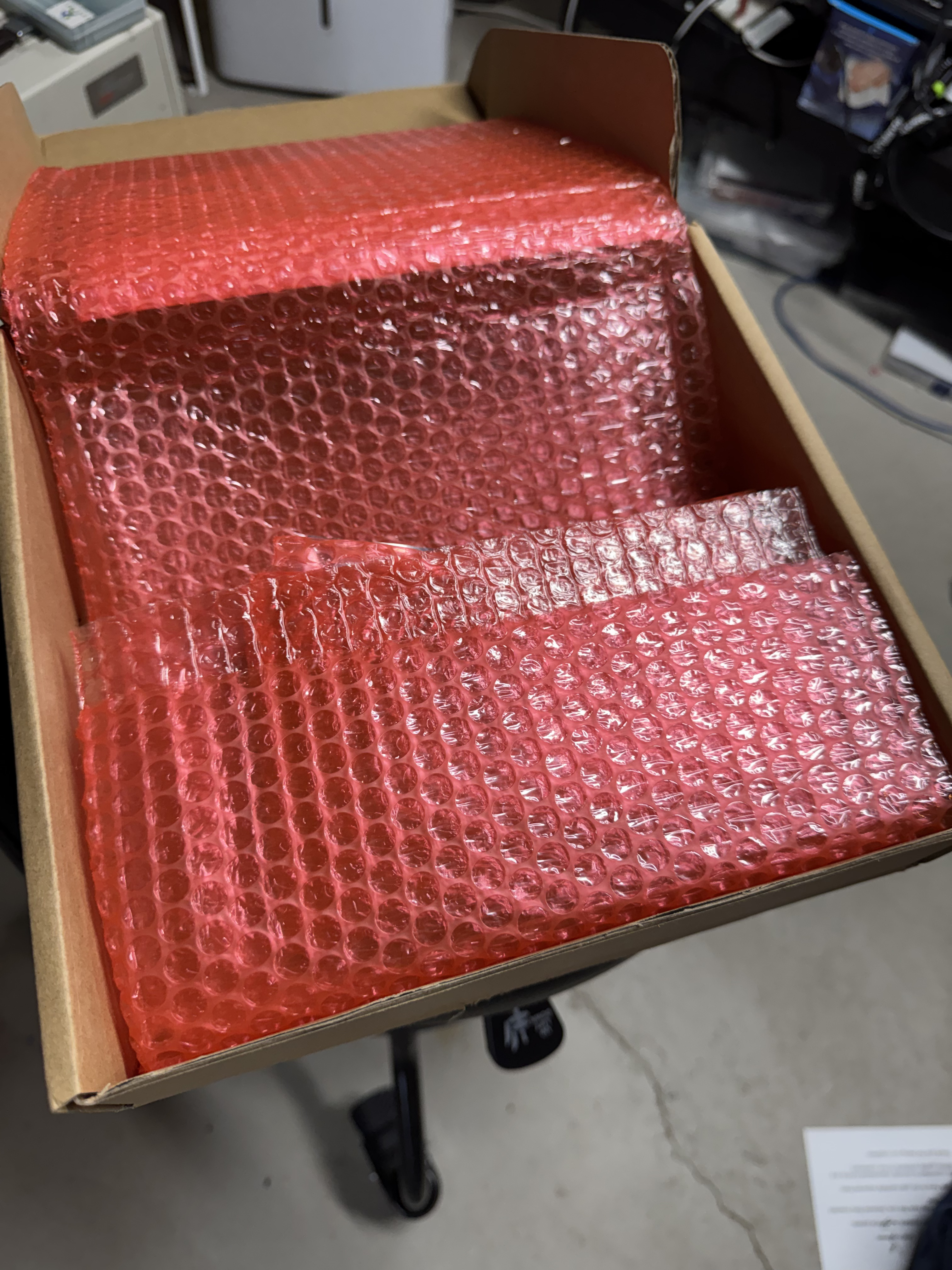
Boards have to be ordered in sets of at least 5, I got 5. I planned to pay to have 4 assembled; I would have extras and would be able to use them in future projects. 5 boards were $25.97 + shipping and took 4 days or so to build. Then 4 boards, assembly and parts all came to $110.59, that part took about 20 days. Most of that cost was the parts (which they handle). Then shipping was around $50 at the time. All together this put each PCB at around $40. I got updates along the way, and this let me work on other aspects of the project while I followed the boards’ progress.

I plan to use PCBWay again in the future for circuit boards I may need created since 5 for ~$26 seemed like a great deal on these complicated ones. I am also curious about using them for CNC on some future projects where parts may need to be made out of metal. 3D printing works for a lot of my needs but a few parts may need to be metal.

Controller Design

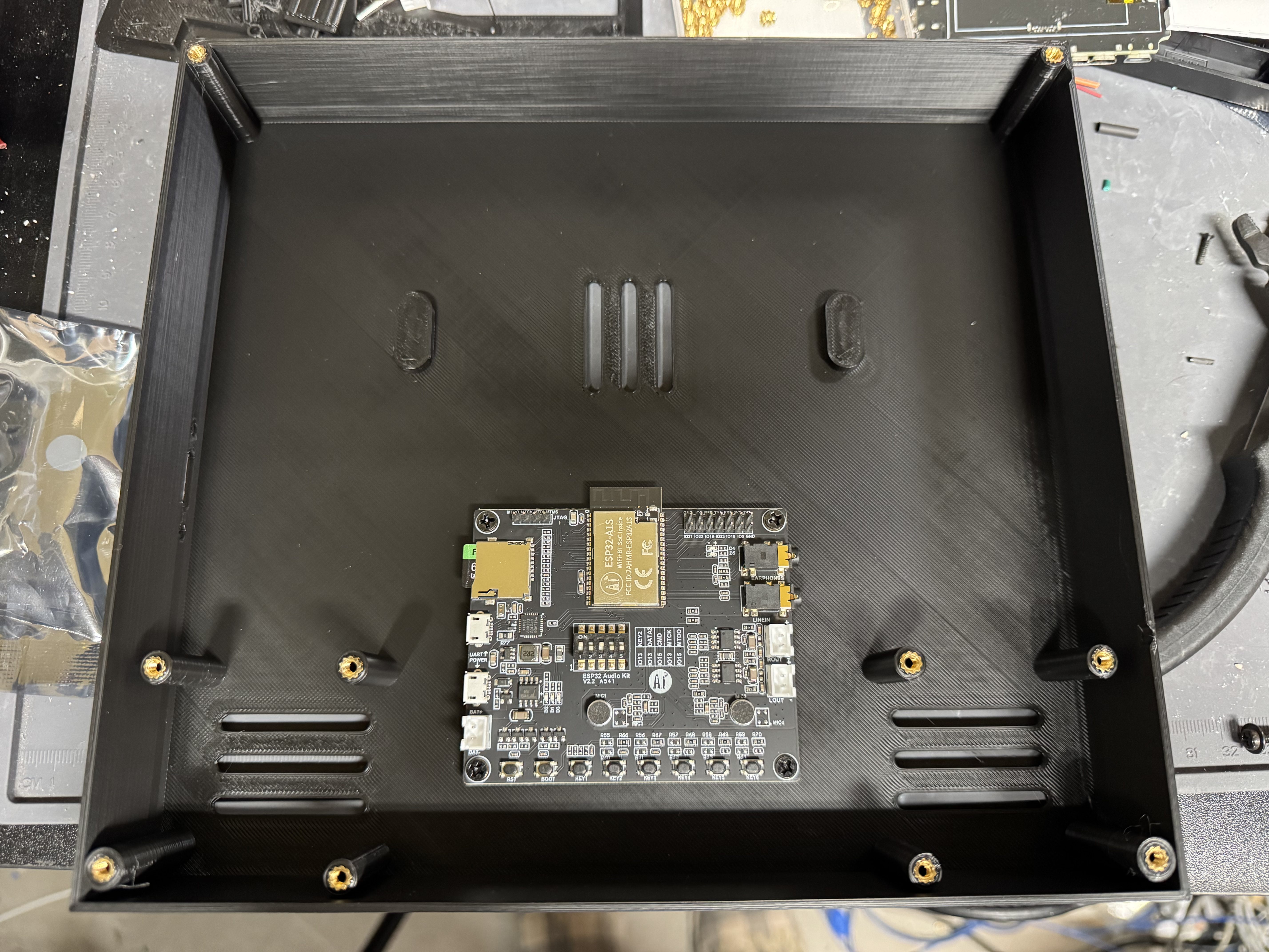
The EPDiy was great for handling the E-Ink screen and uses an ESP32 that I knew how to program for; the issue was it doesn’t have enough ports for everything I need, and I need something to drive the audio as well. I returned to the ESP32 Audio board I used in the History Phone project. As I said before, its documentation is bad, but I now know how it works… so the devil you know…

The idea was to connect these two controllers, EPDiy in charge of user input and output, I called this one the IO Board; then the audio board in charge of SD card full of music, organizing the music, and playback, I called this the jukebox board. They share a serial link. The audio board comes online, checks an index of audio on an SD card. Then after reading the table of contents, sends over what to display to the IO Board. The IO Board sends back button presses as they occur. I haven’t done a project with two ESP32s working together yet, but Claude helped me get the code set up.

Quick Rust Interlude: I was interested in trying to use Rust as the ESP32 controller language instead of C, except when I looked all the libraries that make the audio board work are C, and then the EPDiy libraries are C. I either would need to do a ton of inter-language linking, or I could just do the project in C; which I did instead. Also to use Rust, I couldn’t easily use Platformio which I have been using for ESP32 projects. Platformio allows you to use Visual Studio Code to build out your Arduino / ESP32 projects, and I like it much more than the Arduino IDE or other command line tools.

This was a project I was playing with Claude Code to throw together some of the C. The code is straight forward, and Claude put together a python script which let me manage the songs I was loading on the SD card, setting up the metadata correctly for the audio board to parse. I also was able to add Bluetooth audio support. I set one of the song selections to a special setting, and that puts the device into Bluetooth pairing mode! Once a song is selected, that mode disables itself.

3D Model

I have been trying several different 3D modeling systems recently. For years now I have used Solidworks, and it works well other than it’s a giant Windows app that periodically gets hours of patching done to it. I tried OnShape, a web-based 3D modeling tool, after I ran into someone from the company and they recommended it. You get to use all their standard tools for free, as long as your designs are public. I gave it a spin. It worked decently well. My normal keyboard shortcuts didn’t all work, but that is from years of using Solidworks, not their fault. The main issue I kept having was the mating system. Theirs is MUCH different from what I am used to (again from years of Solidworks) and I kept stumbling.

This holiday season Solidworks for hobbyists was on sale, including the standard Desktop version AND the web version. I had to pay twice but got a year of each for the normal $49 price. I want to love the web version. My models aren’t that complex, and honestly Solidworks is one of the last things that keeps my desktop computer on Windows. I will keep experimenting with it, but I did find it slower and more cumbersome than the desktop version of Solidworks. In the end I made an early render in each but did the majority of the work in Solidworks Professional, the desktop version.

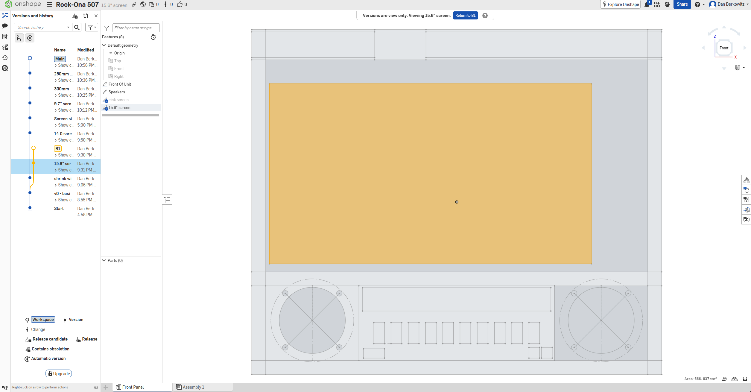
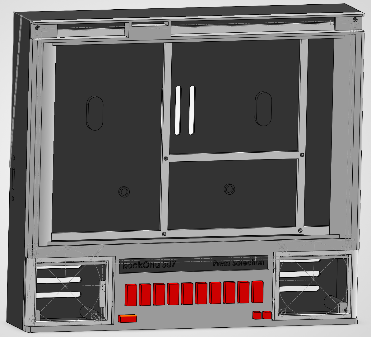
The original version of the Rock-Ola 507 was large, larger than a photo may let on. It was 18 inches wide, by 15 inches tall, and 6 inches deep. It was also 30 pounds… It was BIG. Here is a screenshot of OnShape with a 15.6″ screen put into a version where I had already shrunk down 2 inches.

Quick aside: One neat feature of OnShape is git-like versioning of your models. You can see on the left I tried different sizes and different screen ideas.

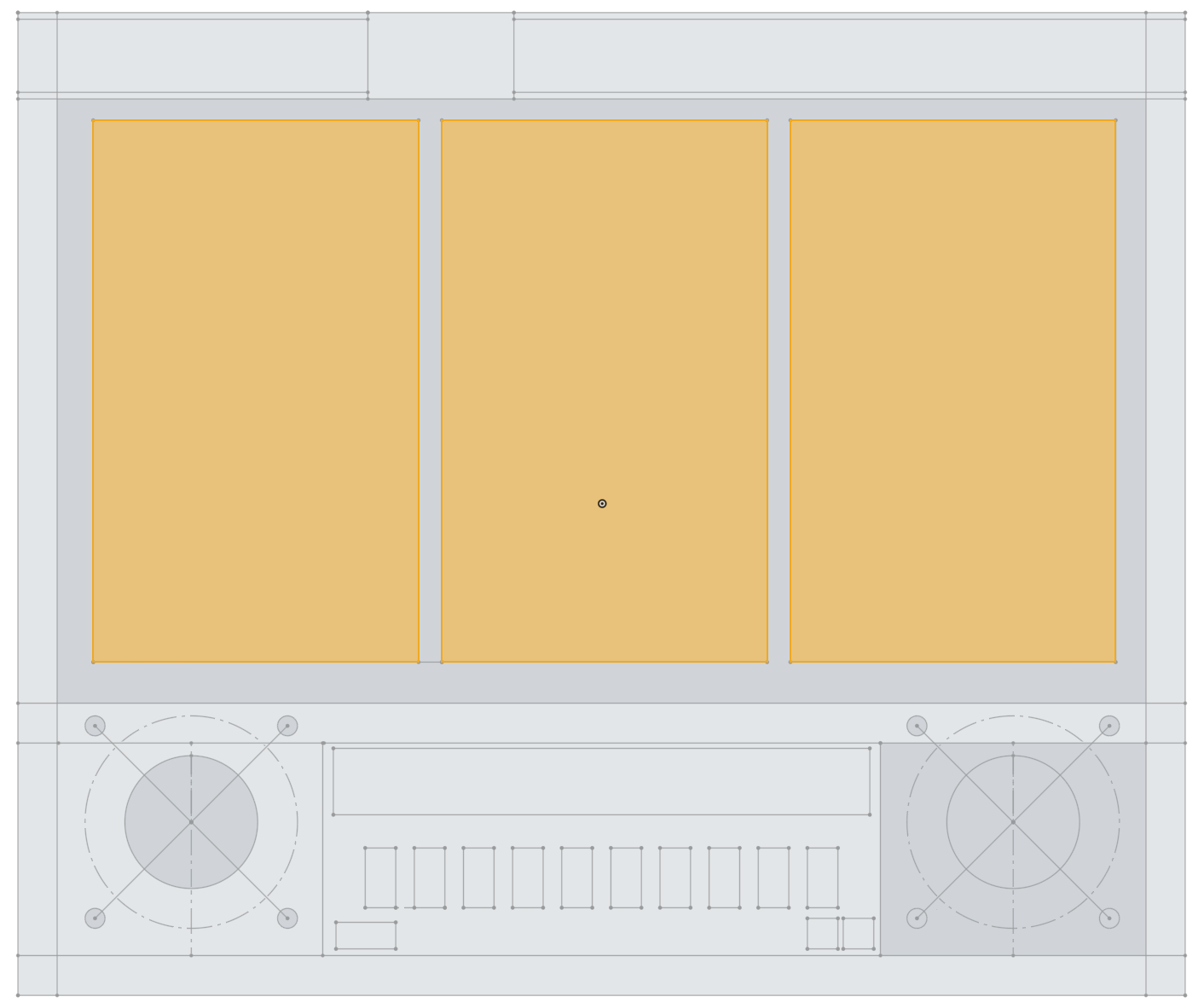
Here was another attempt at fitting different screens, this time I had 3 x 7.5″ (kindle like) screens in the device. Still way too big and would require 3 EPDiy boards working together (I did get 4 in case I went that route) greatly increasing the cost. This would be good for hanging in a garage or basement, but I wanted something a bit more compact.

I ended up shrinking the whole thing to ~9 inch across, about 50% the original one. This also allowed me to easily fit in on my 3D printer in one piece. I got a Sovol SV08 a bit ago, its 350mm by 350mm print bed made easy work of this.

This is a closer to finished Solidworks model. I am not showing the screen. I had an idea of using cloth for the speakers to give it a more warm feeling. I did try this on the first unit I made of two, sewing is not my thing.

I got a 9.7″ E-Ink screen off amazon, that turned out to be around the same price I saw at places like eBay and could come quickly. At $68.99, this was the largest expense of the project for one item.

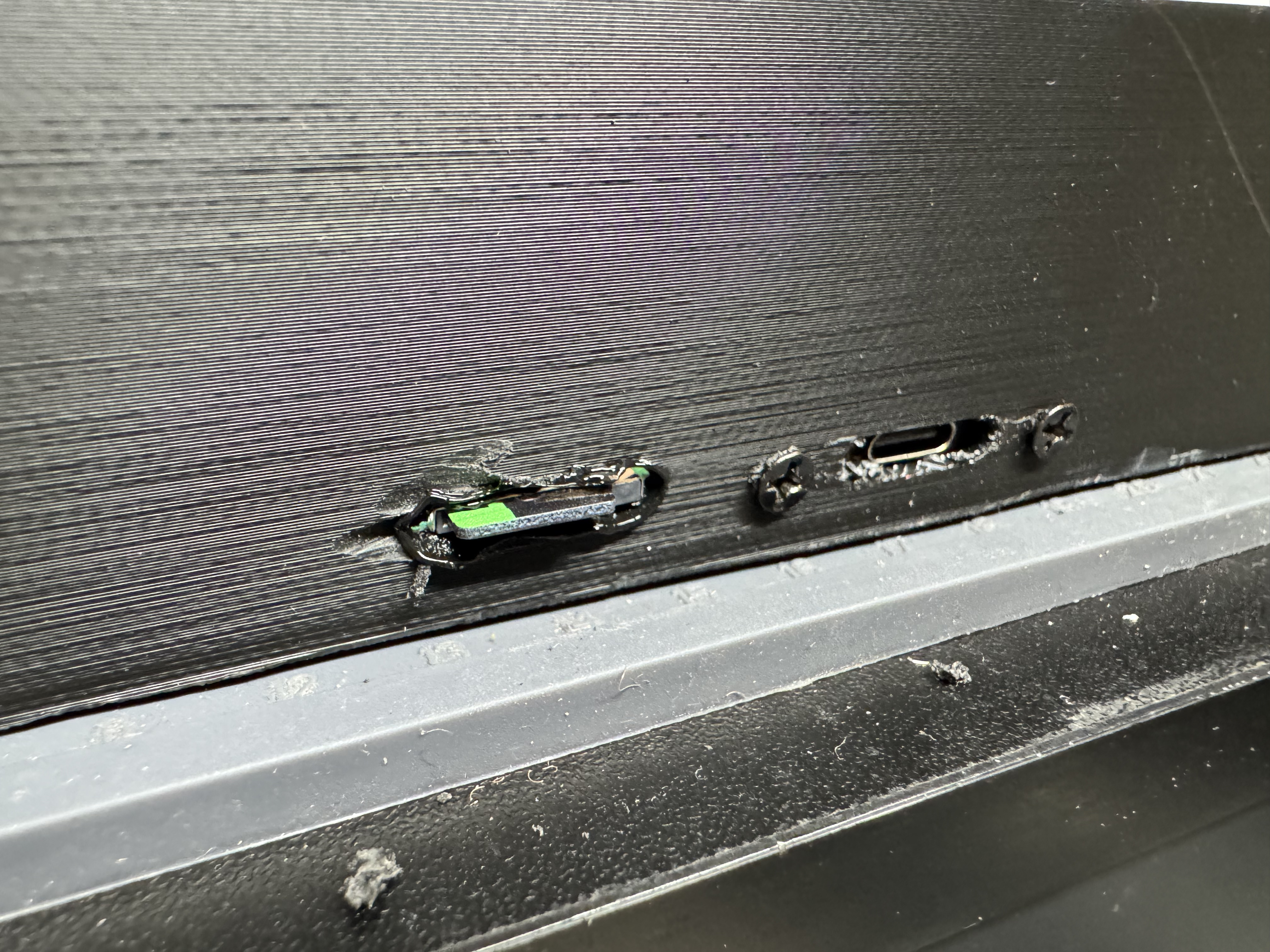
Much later I realized I had one place for the USB C power to go into the side of the case, but I didn’t have anywhere for the SD card. This would mean I had to open the unit every time I wanted to change the songs on it. I got a SD card extension cable, and already had a Dremel… so I made another hole in the side…

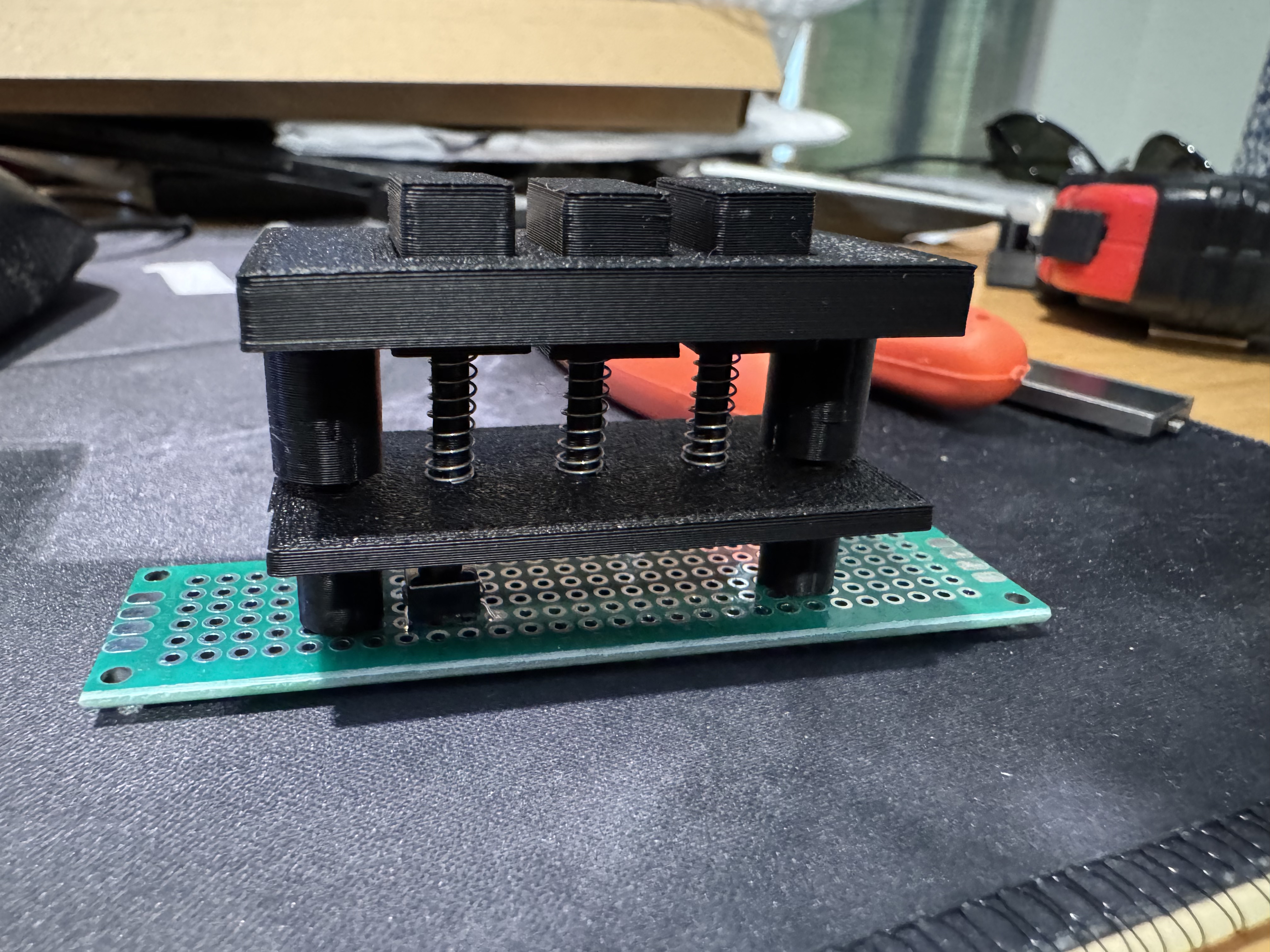
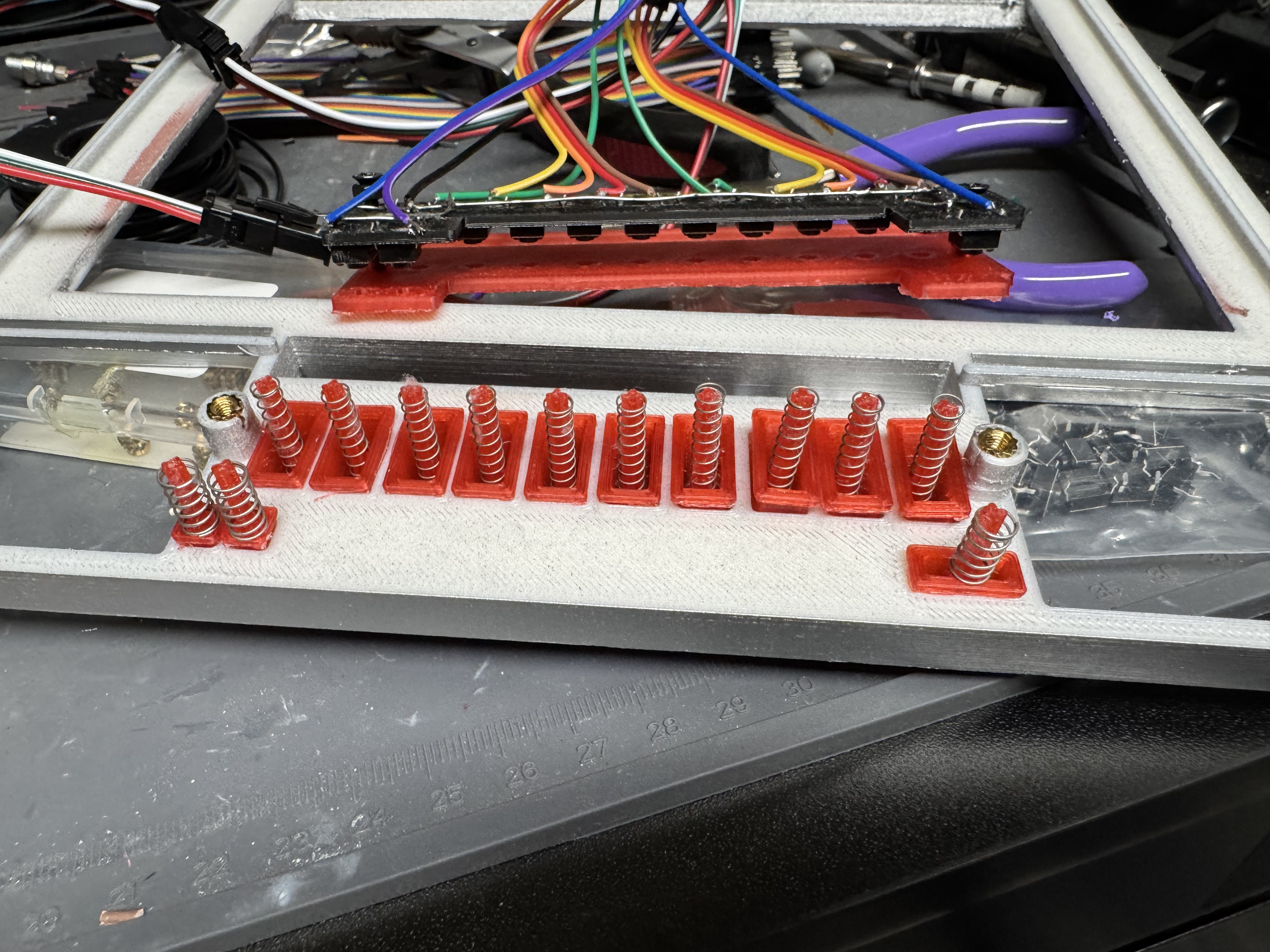
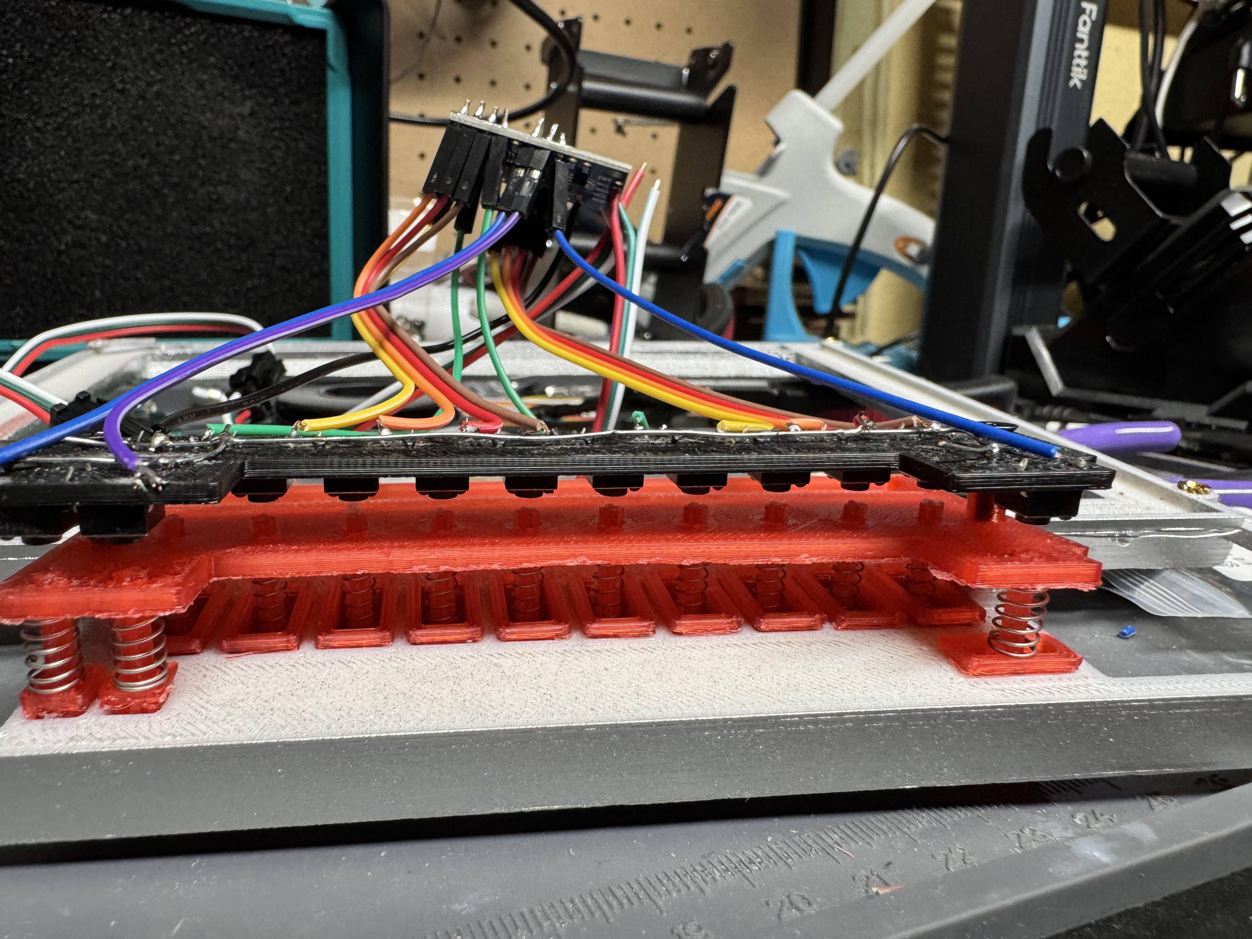
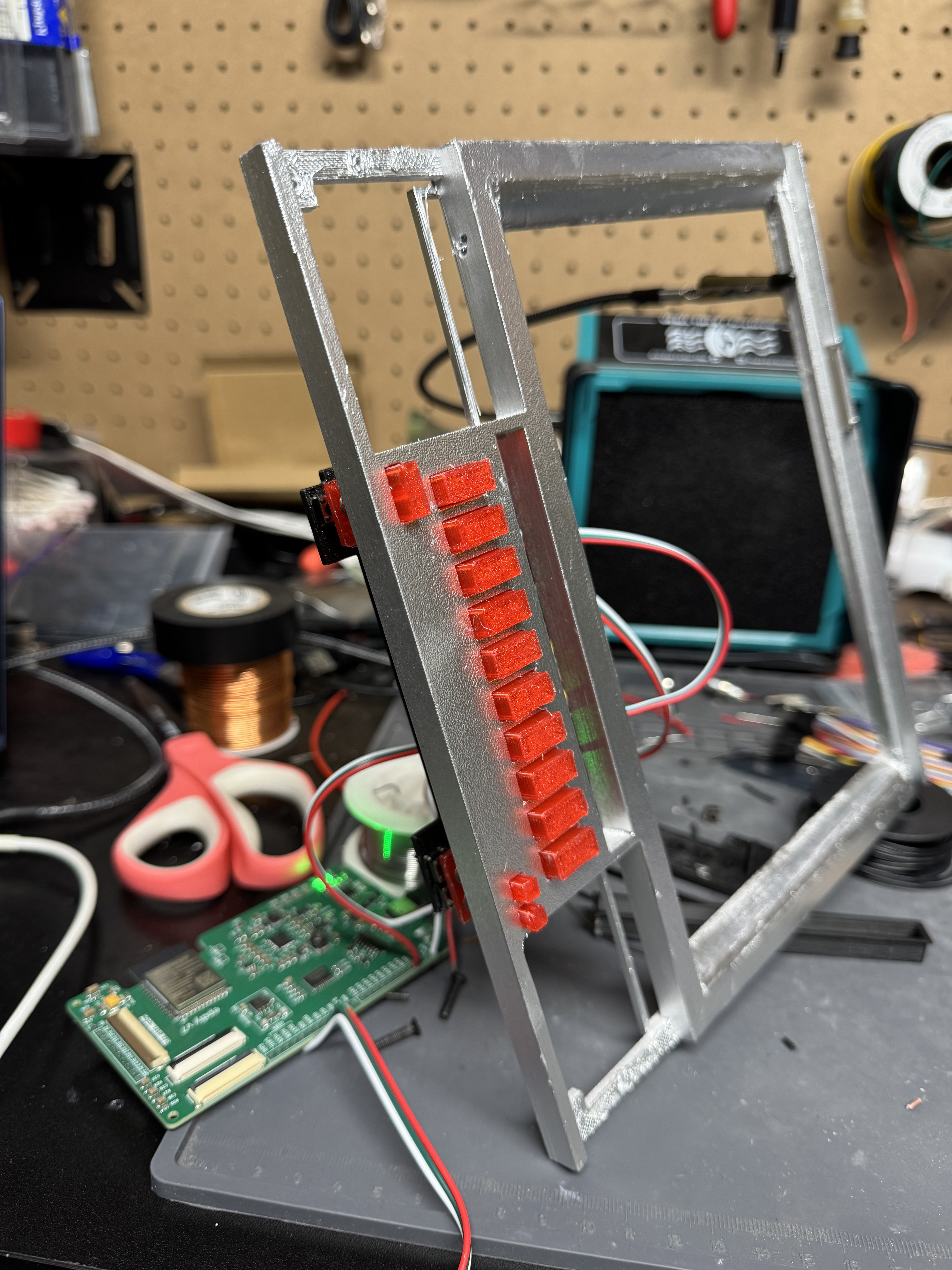
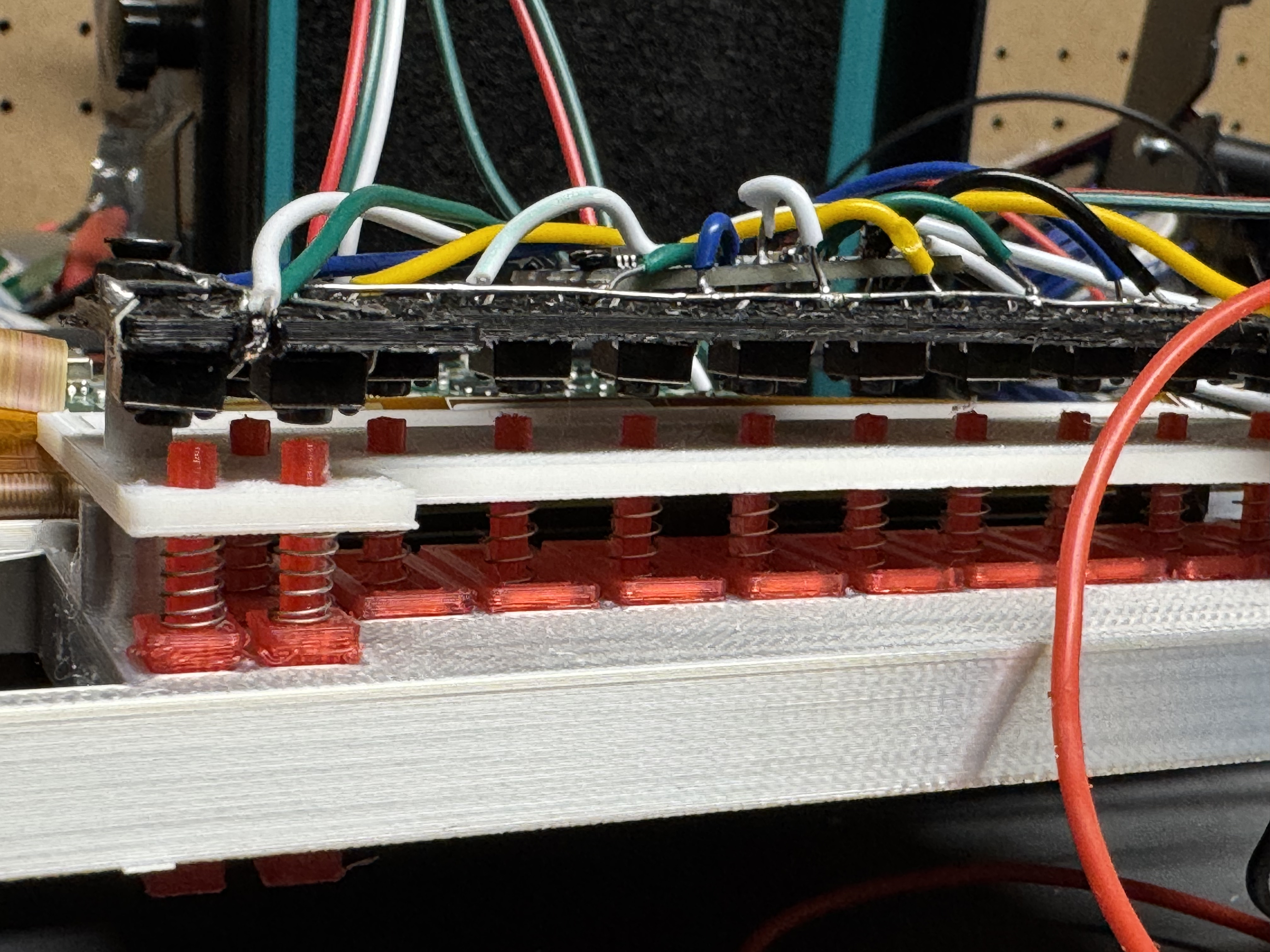
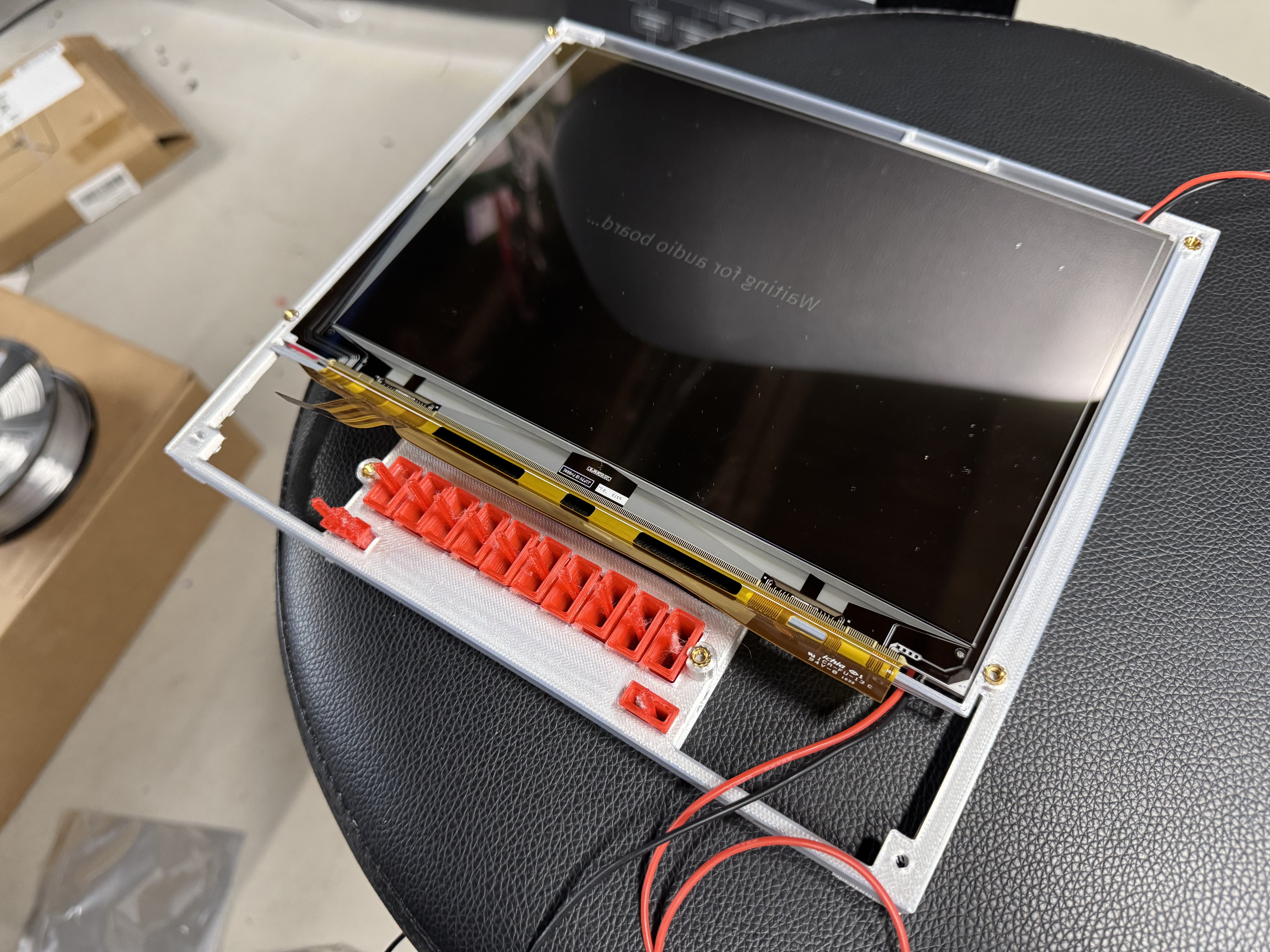
Part of this build was figuring out a way to make the buttons feel nice. I tried several iterations and different designs. I wanted a longer throw, but something electrically simple, and could fit in the case.

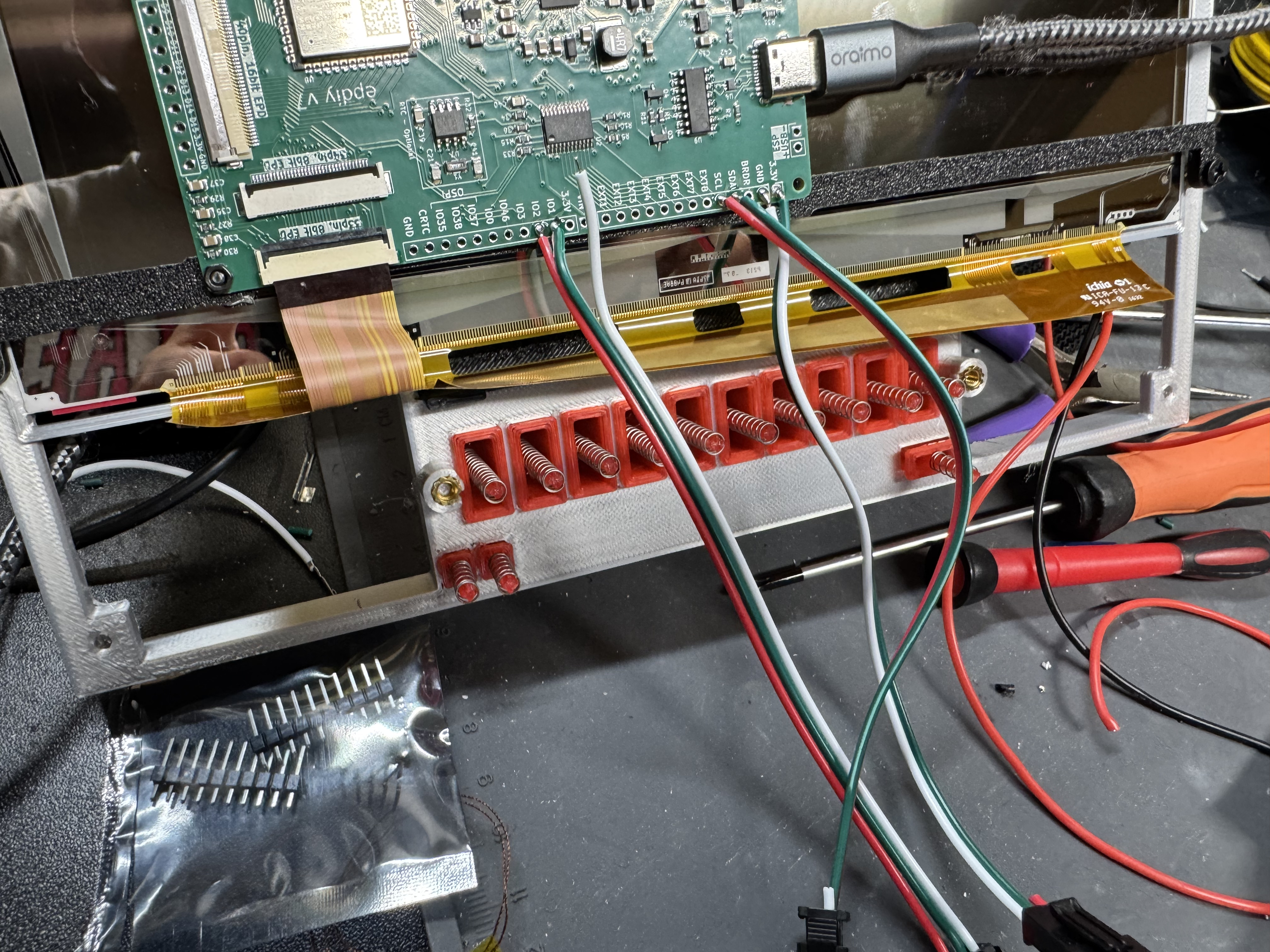
I ended up with this 3-layer design. Big button with a stem, that goes through a guide that has a spring, that clicks a little push button. You get the nice throw of the switch, a good click, then it bounces back.

Part Selection

I have mentioned selecting the audio board, selecting the screen, selecting the buttons. One important thing I haven’t mentioned for an audio system is selecting the speakers. The documentation for this board mentions that it can drive 3W, 4Ohm speakers. I tried 3 different ones in different sizes thinking how different could 3W speakers’ sound. Apparently very different. The small ones had a very hollow sound. I went with the bigger speakers. The audio board needed JST-XH 2.54mm connectors in male, which I couldn’t find documented anywhere.

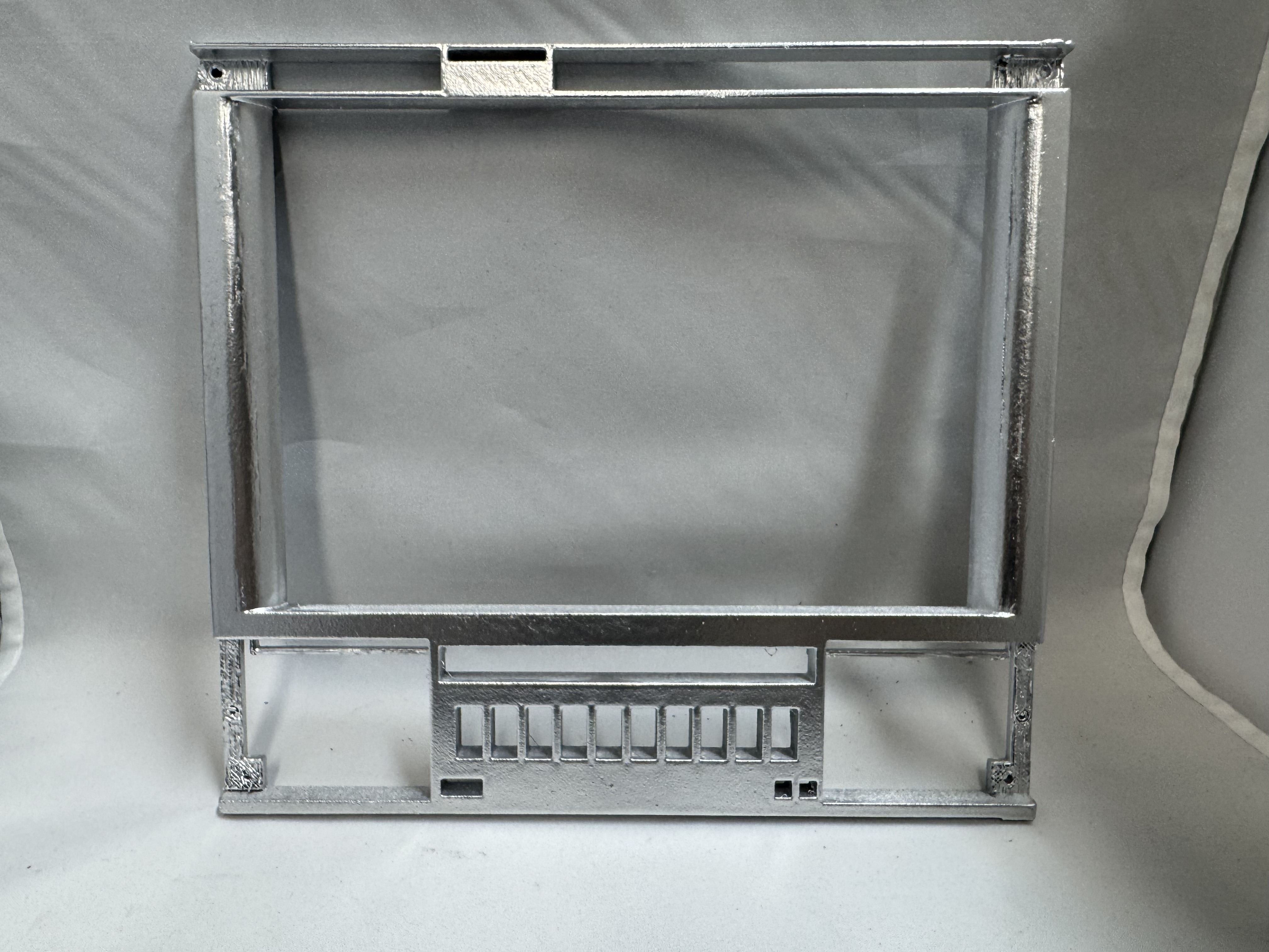
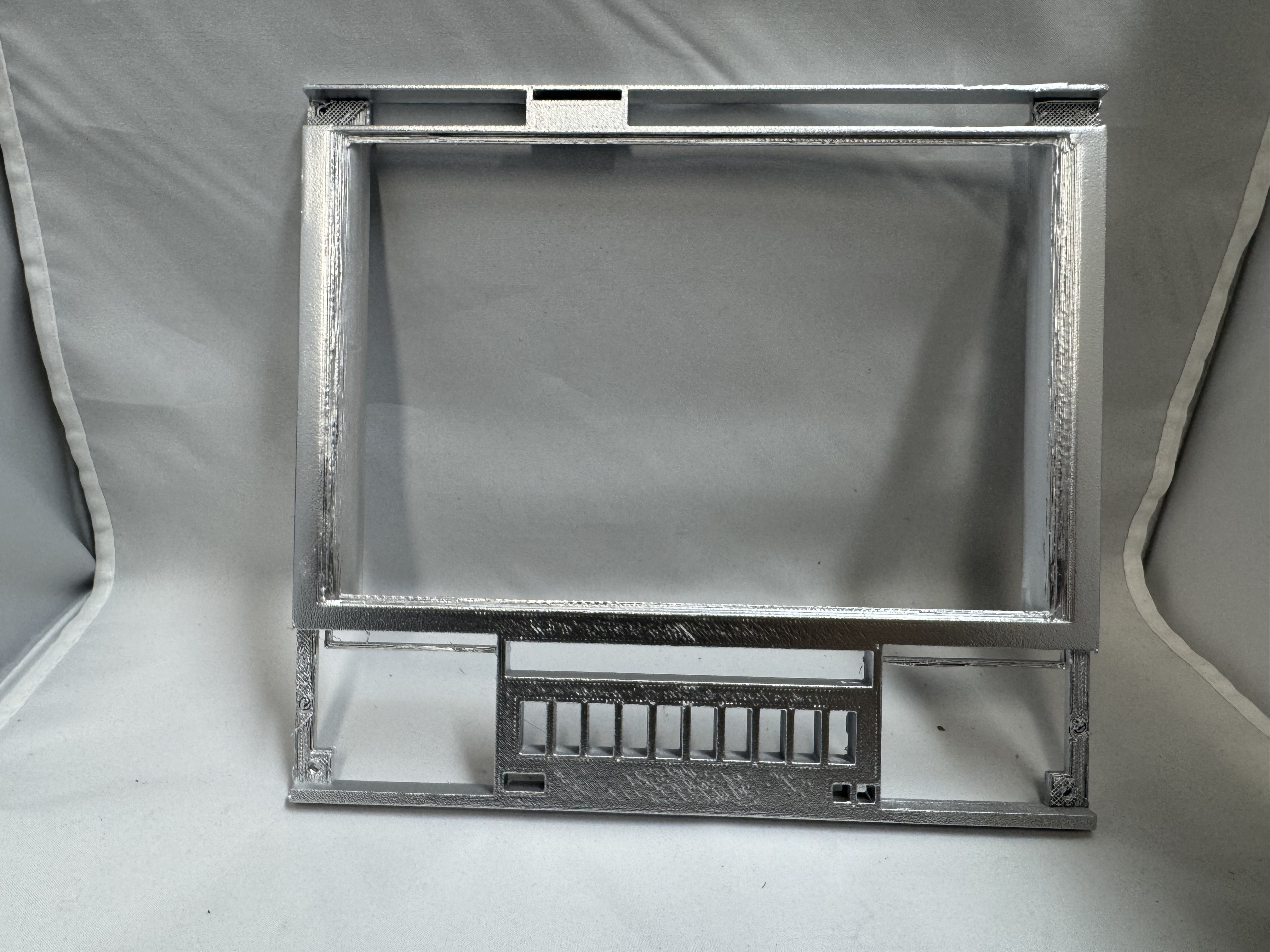
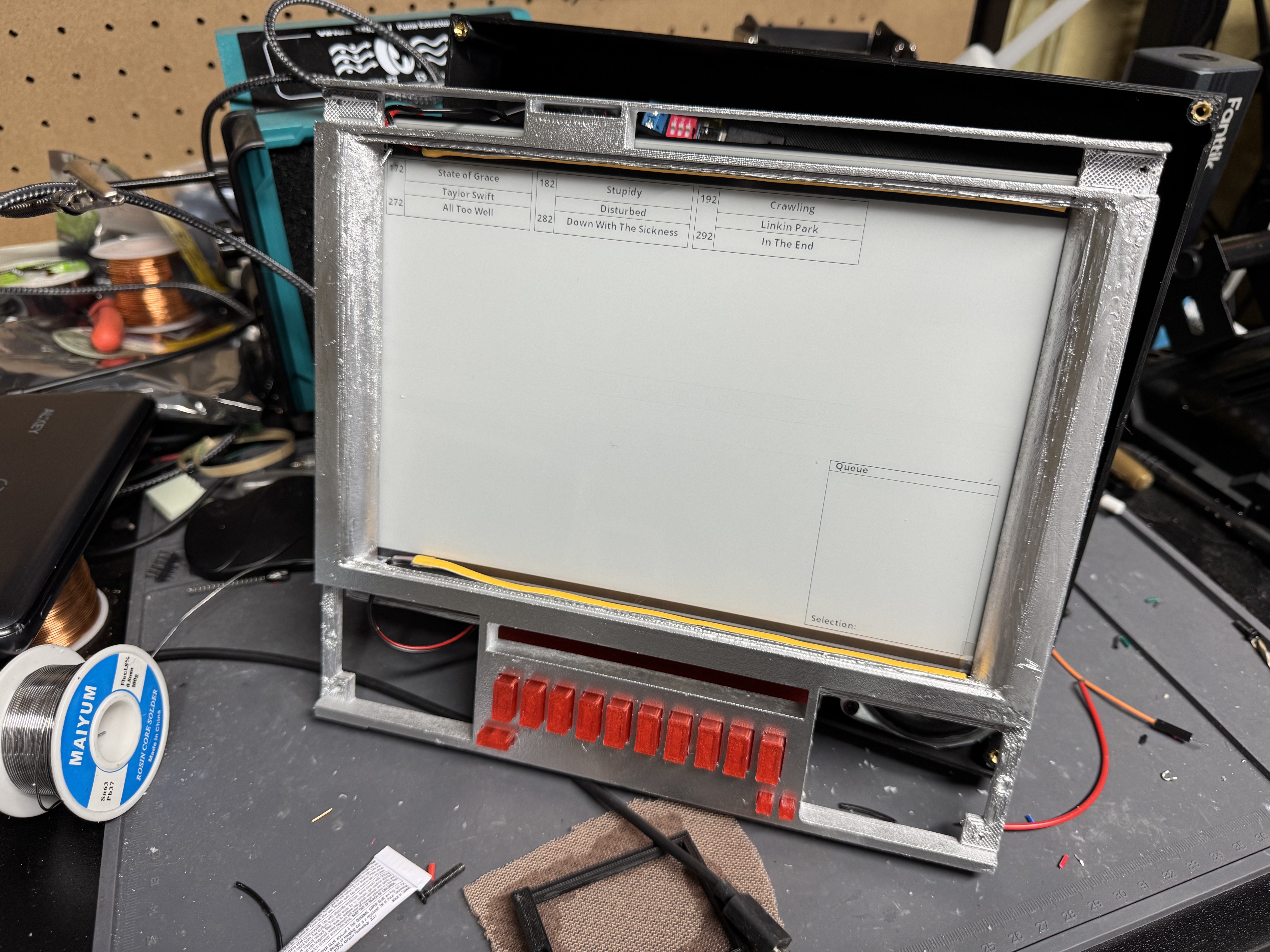
For filament, I did most of the prototypes parts in black. I knew I wanted a silver front from the start, and that led me to trying silver spray paint, more on that in a second. The second big personality piece is the glowing red front buttons. I got transparent PLA filament and put a strip of lights behind the buttons. This worked well. I may have instead put just a few LEDs behind the buttons instead though, because right now the LED strip is tied into the same power source as the front LEDs, and I want to increase the brightness to the buttons but not the front lights. Something to fix in future versions, or a small upgrade. Splitting the button lighting control would also allow interesting effects for if the system is left on for a while with nothing playing, dimming the screen and buttons separately.

Assembly

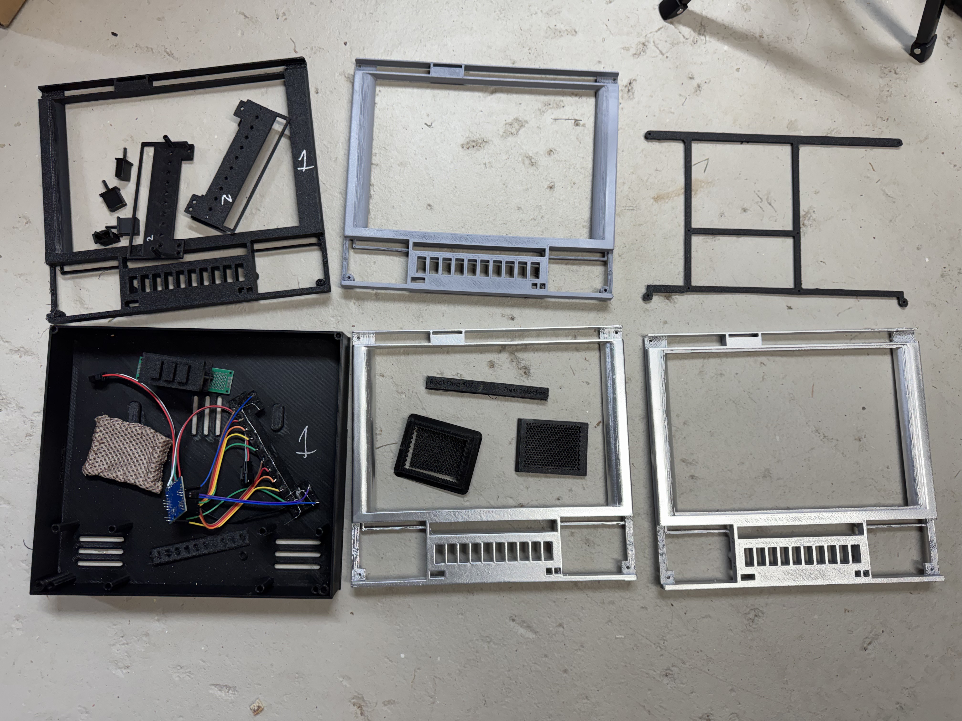
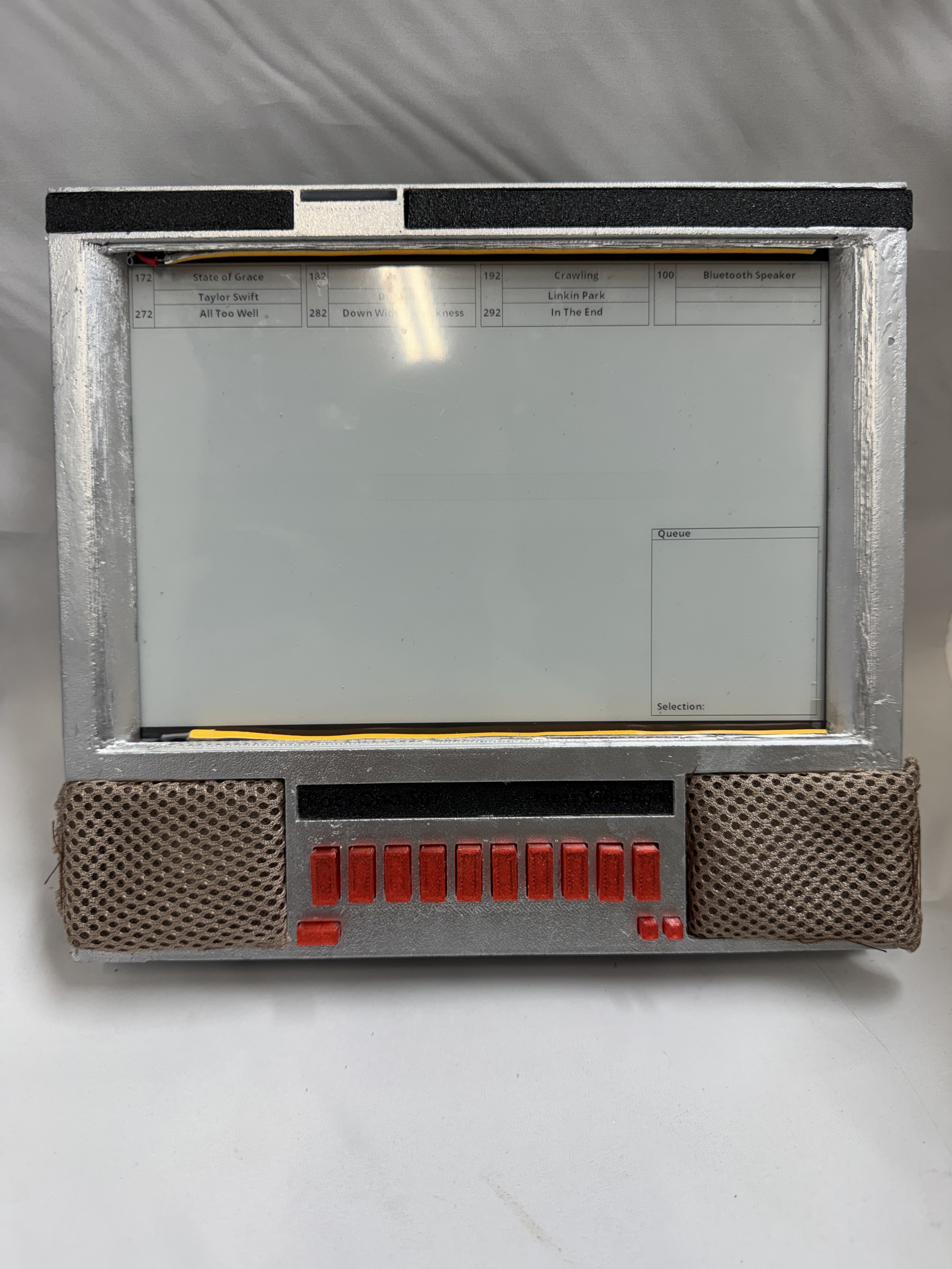
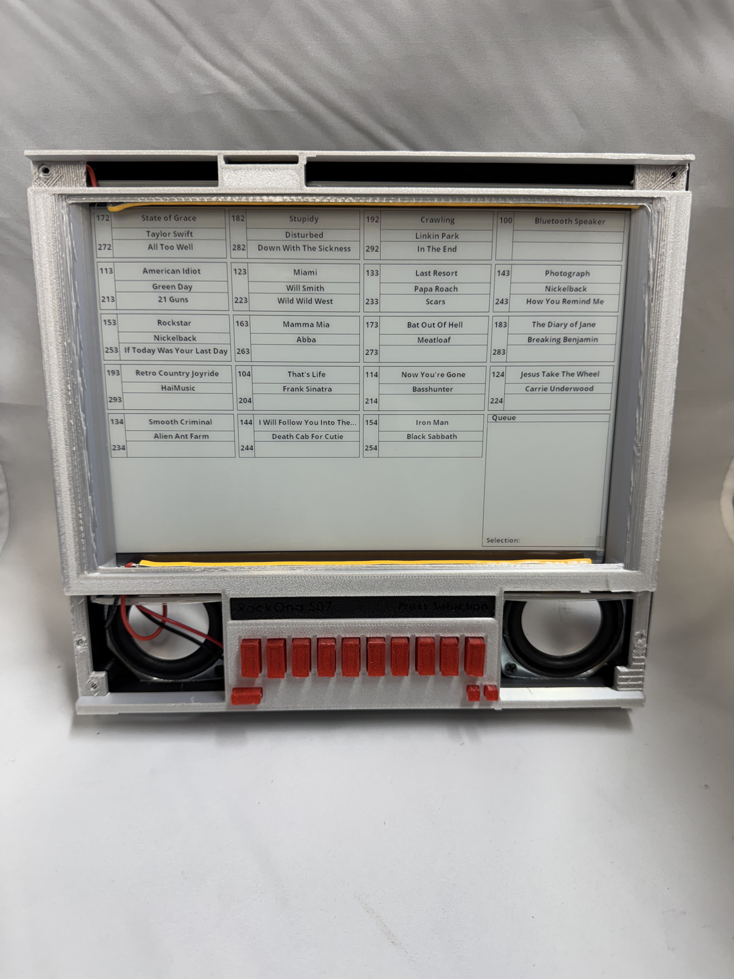
With boards in hand, Claude helping to put the code for them together, and the simple buttons, the hardest part of this whole project was printing it out and putting the pieces together. I will readily admit I am not the best spray painter. It also didn’t help that the chrome-looking spray paint wants 65F-90F degrees and 60%+ humidity to properly paint. Being winter around NY left me limited days where I could attempt different spray-painting techniques. I tried the whole proper 3D printing, sanding, filling, sanding, priming, sanding, spray painting for the first unit. It came out, meh. I think I over sprayed. I ended up making two units, one where I tried a few front plates, with different sanding and spray-painting techniques, then one that I just got silver filament and 3D printed it, calling it a day.

Button Assembly

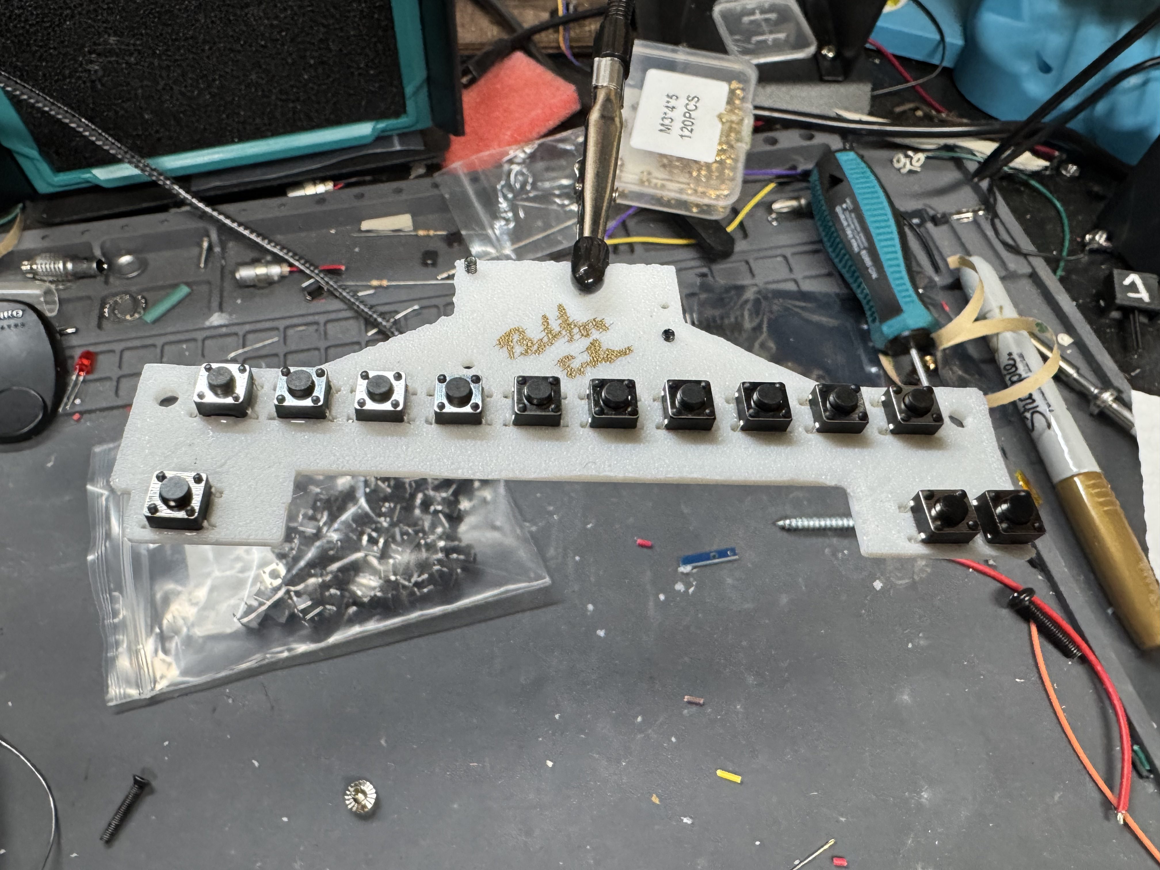
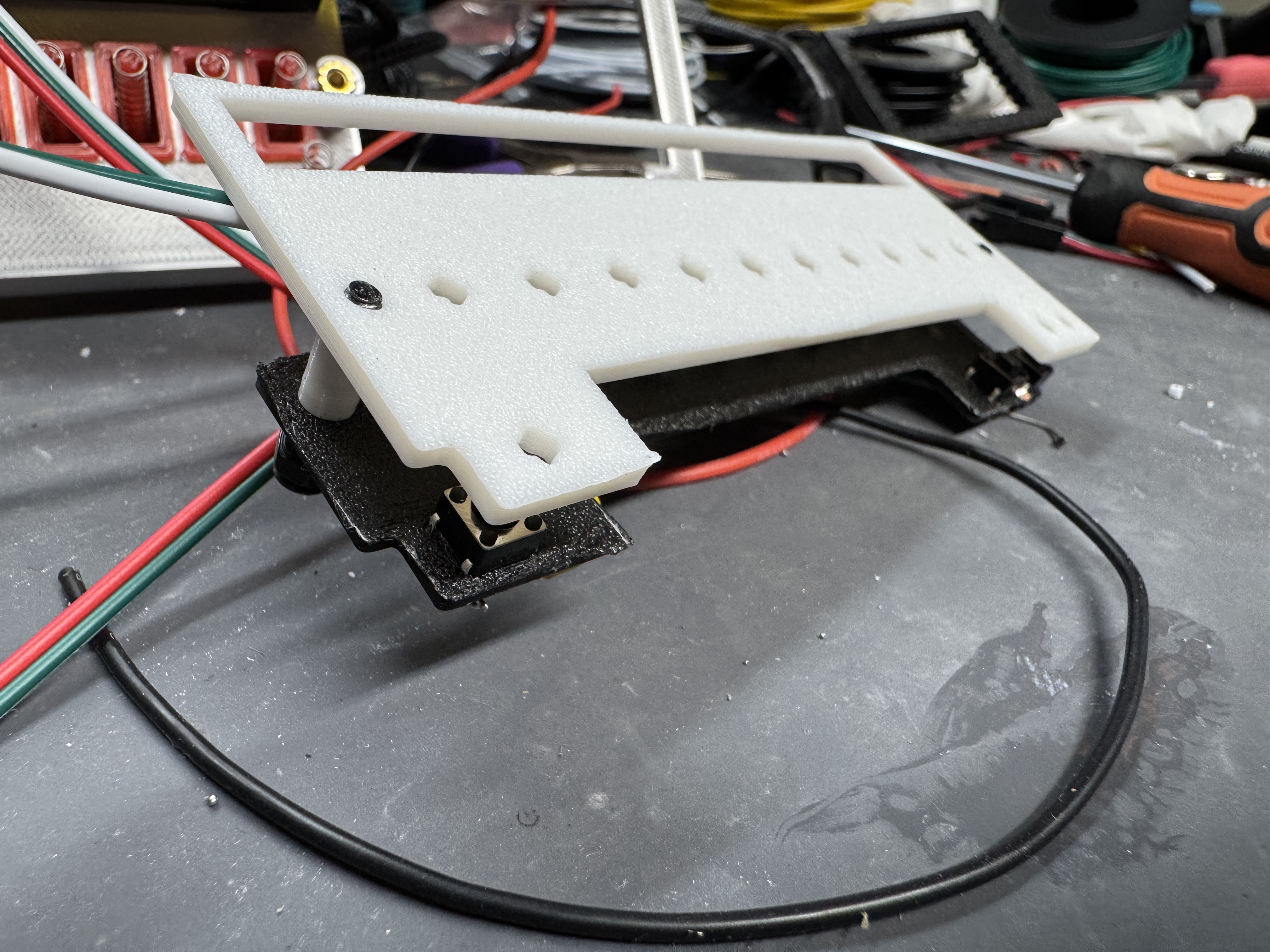
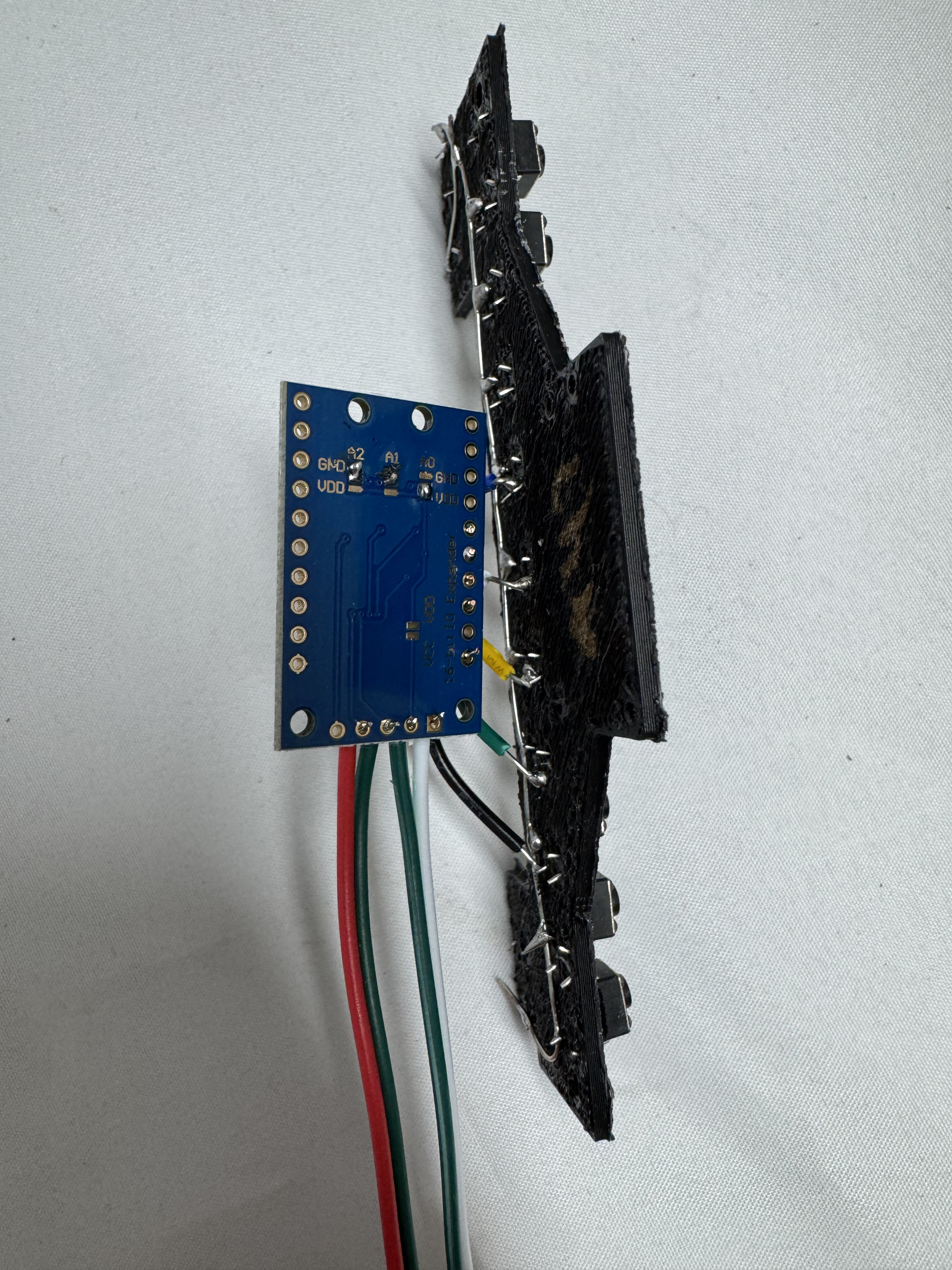
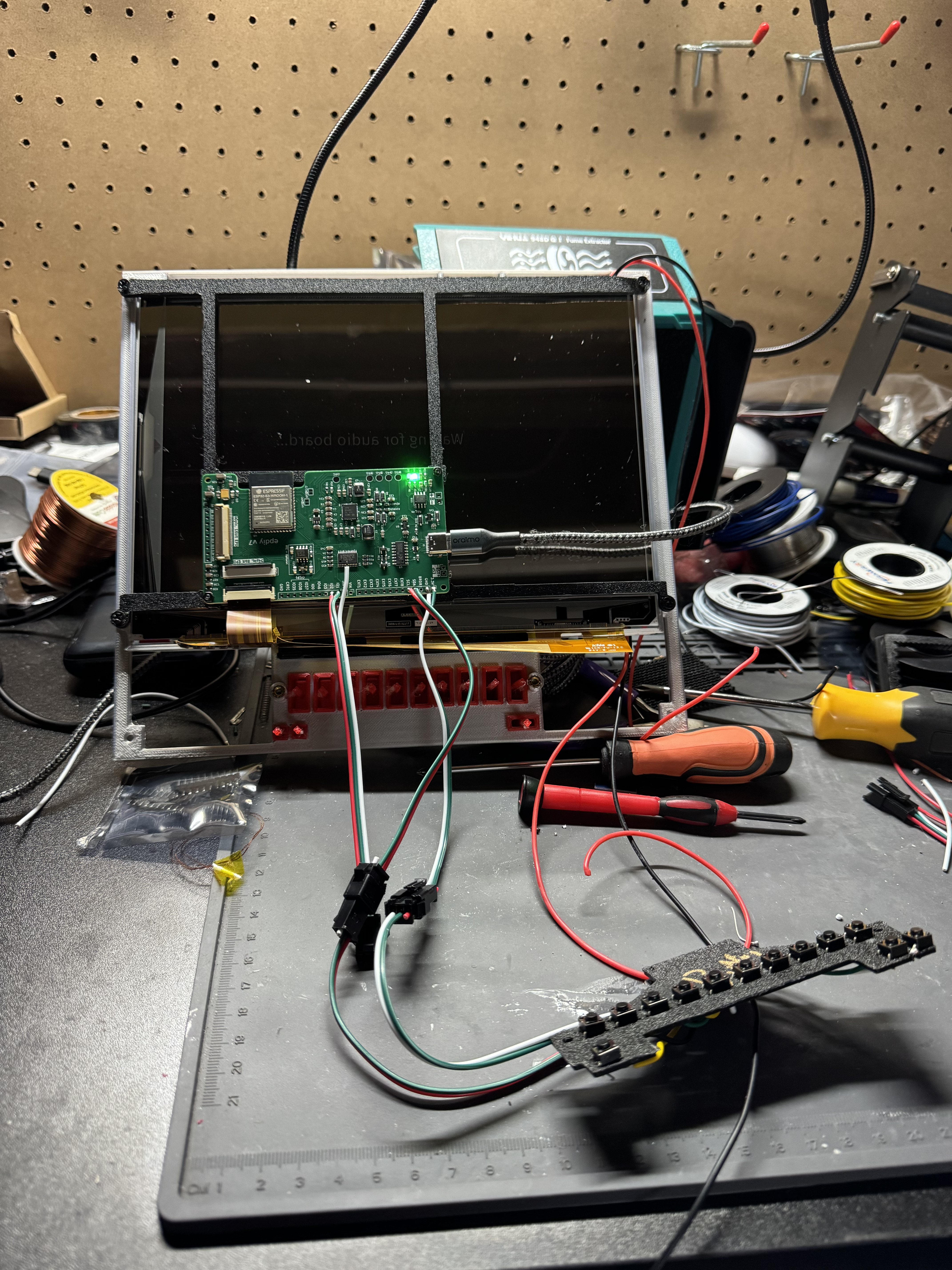
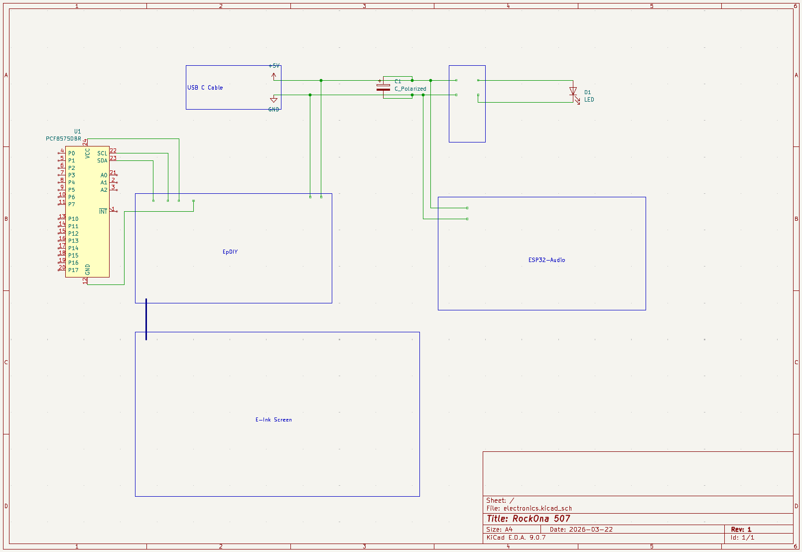
I assembled the front. Soldering the buttons to a PCF8575 IO Expander, this helped give me more buttons over I2C to the EPDiy board. I created a version 1.1 of the button board. The first version had wires going everywhere which made it hard to put into the case. The updated version I put the chip on the same 3D printed part, greatly shortening the runs and making it much cleaner inside. I did get one of those PCF8575 that was bad, and that took me a bit to track down, it would spray out random buttons being hit. I thought it was my circuit. One great upside to the PCF8575, it uses 2 wires for power, and 2 for data, making the whole button assembly very self-contained.

An important note about EPDiy and PCF8575. The E-Ink part of the panel uses 0x20 ID on I2C to communicate. I had to solder on the back of the PCF8575 to change its ID to 0x21.

I got the final front panel and installed the full button assembly. I put the EPDIY onto the bracket for the screen. Then installed the E-Ink screen and its backing bracket. I had put LEDs from an LED strip I got on the front below the screen, and above, then another short strip behind the transparent buttons. Soldering the wires onto the “easy to cut” LED strip was not fun. I soldered all the LED strip positive wires together, and then the negative wires; connecting them into one of the quick connect connectors I had. The front panel was done now. I wrote the IO Board code to the ESP32 (which I ended up doing multiple times), and it was good to go. I did originally want to have text with lights behind it in the top cut out area of the front, and above the buttons, but this was added complexity for a small nice visual thing. I may add that in another iteration.

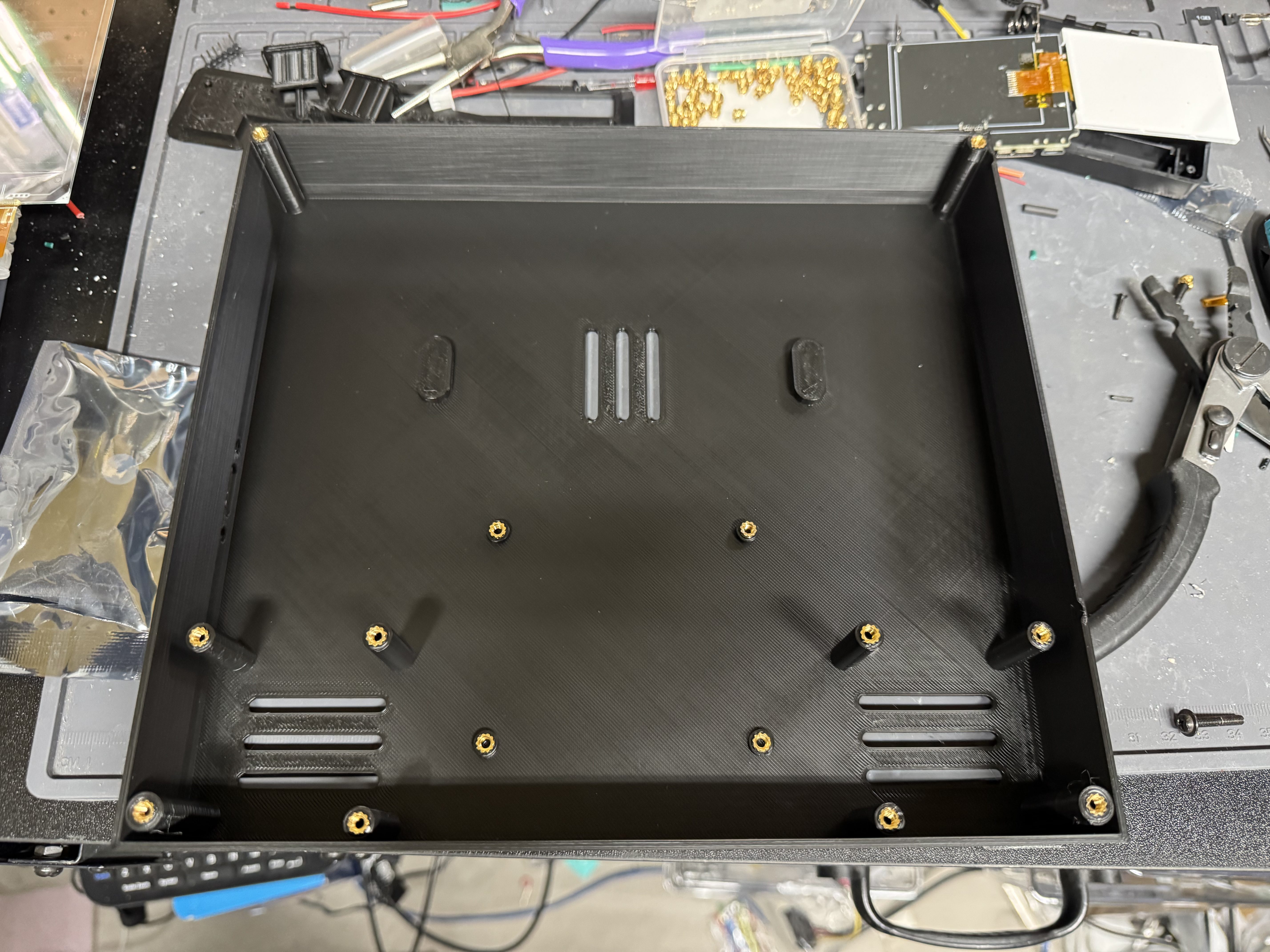
I made wide use of one of my more recent favorite 3D printing tools, heat set inserts. They are tiny metal screw points you melt into your print with a soldering iron. They give great M3, M4, or M5 mount holes that you can use in a project and not worry about wearing out the plastic. They are also $10 for 120 of them.

Electronics

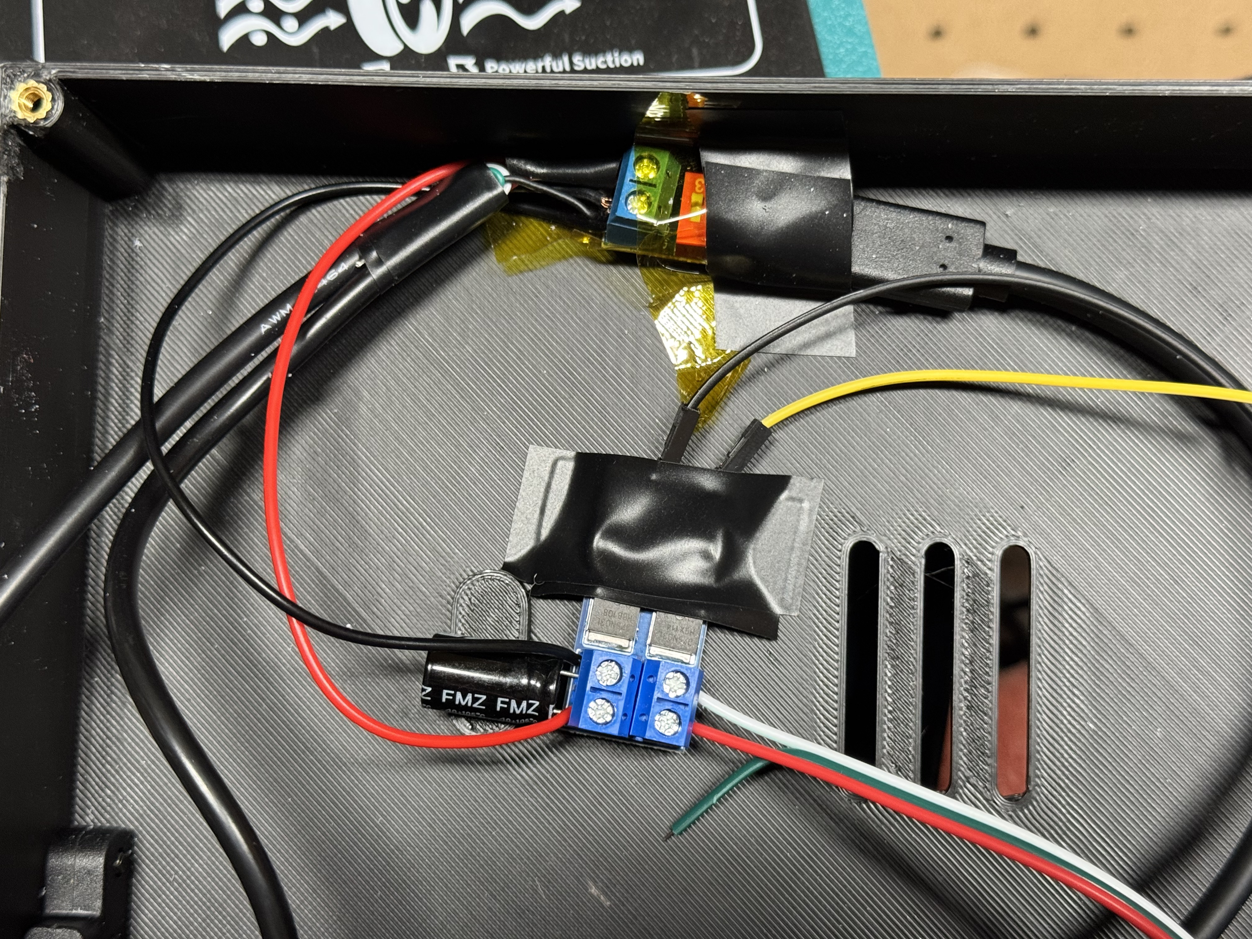
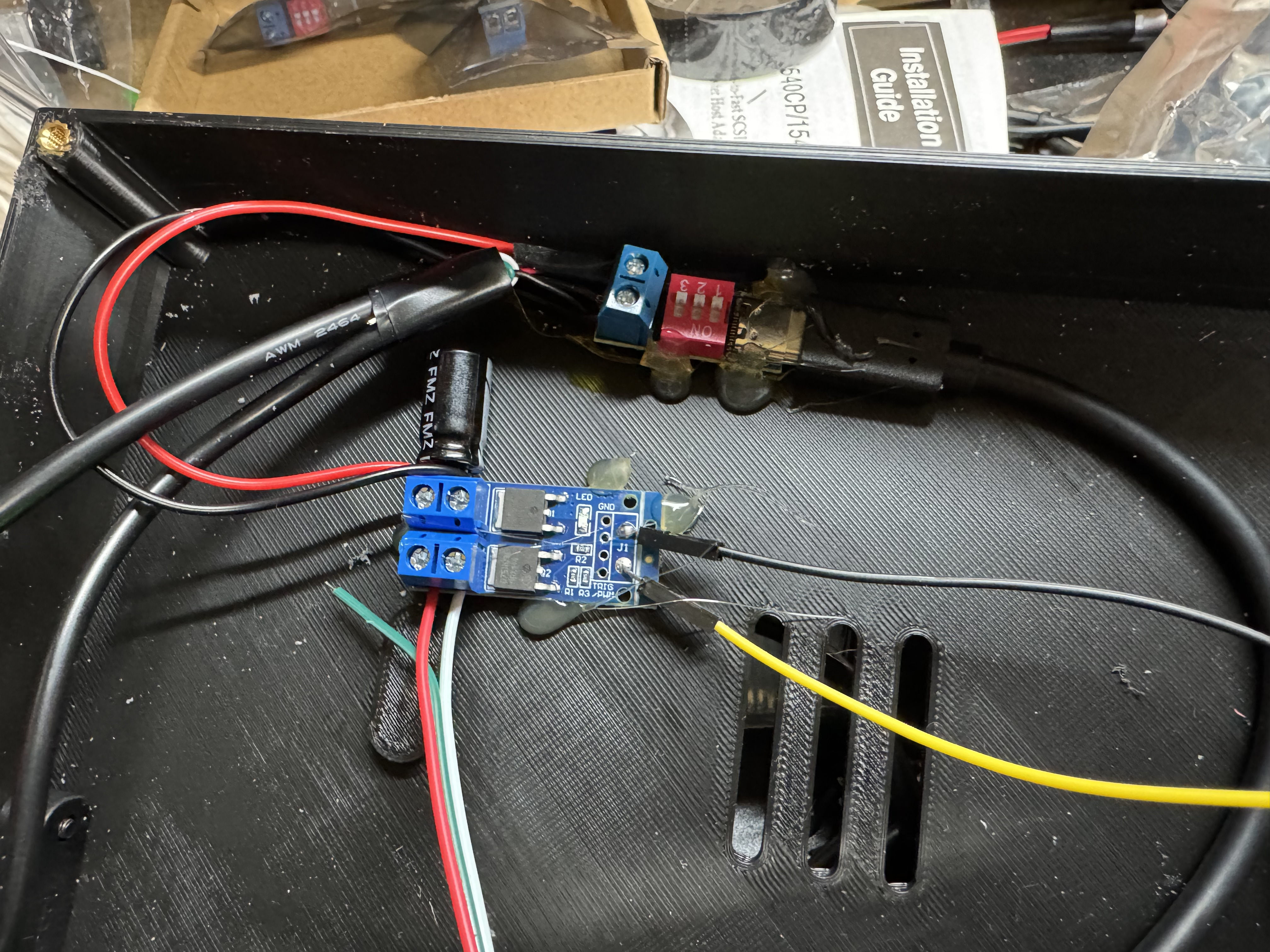
Time to wire the body. I put a USB C port in the side of the case which allowed one power plug for the device. I didn’t want to have one of those devices that had USB C but not actually USB C Power Delivery negotiations. I got a little chip that allows you to declare which voltage you want over USB C. I set that to 5V.

Power goes from that board, into a USB mini cable for the jukebox board, a USB C cable for the IO Board, and a pair of wires into a MOSFET. I haven’t worked with MOSFETs to control LEDs before, but I needed it to drive the LED strips I put around the screen, and behind the buttons. This actually gave me issues because (I learned later) MOSFETs are good to regulate power but also are noisy on power lines turning on and off. They caused chaos on the power line, and I ended up putting a 1000uF capacitor on the input side of the MOSFET to help smooth out the power line. Without that, the IO and jukebox boards power was so dirty they kept blinking on and off.

Prepare for Rookie lvl 101 Circuit Design!

I had a bunch of quick connectors that usually are for LED lights, but I used them anywhere I may need to often connect and disconnect sub-components. If one component has more than one connector going to it, I will reverse the male/female side of the connectors to make it clear which one plugs into where. Things like PCF8575 -> IO Board, IO Board -> Jukebox board, LEDs on front panel -> MOSFET. This allowed me to quickly remove things when needed. I soldered an extra pair for the serial connection that would go between the two ESP32s.

The speakers had 4 metal anchor points around them, and I was having a hard time fitting them, so I just cut off one and it fit perfectly. The heavier speakers also helped the system stand upright, bringing a good lower point of gravity to the unit.

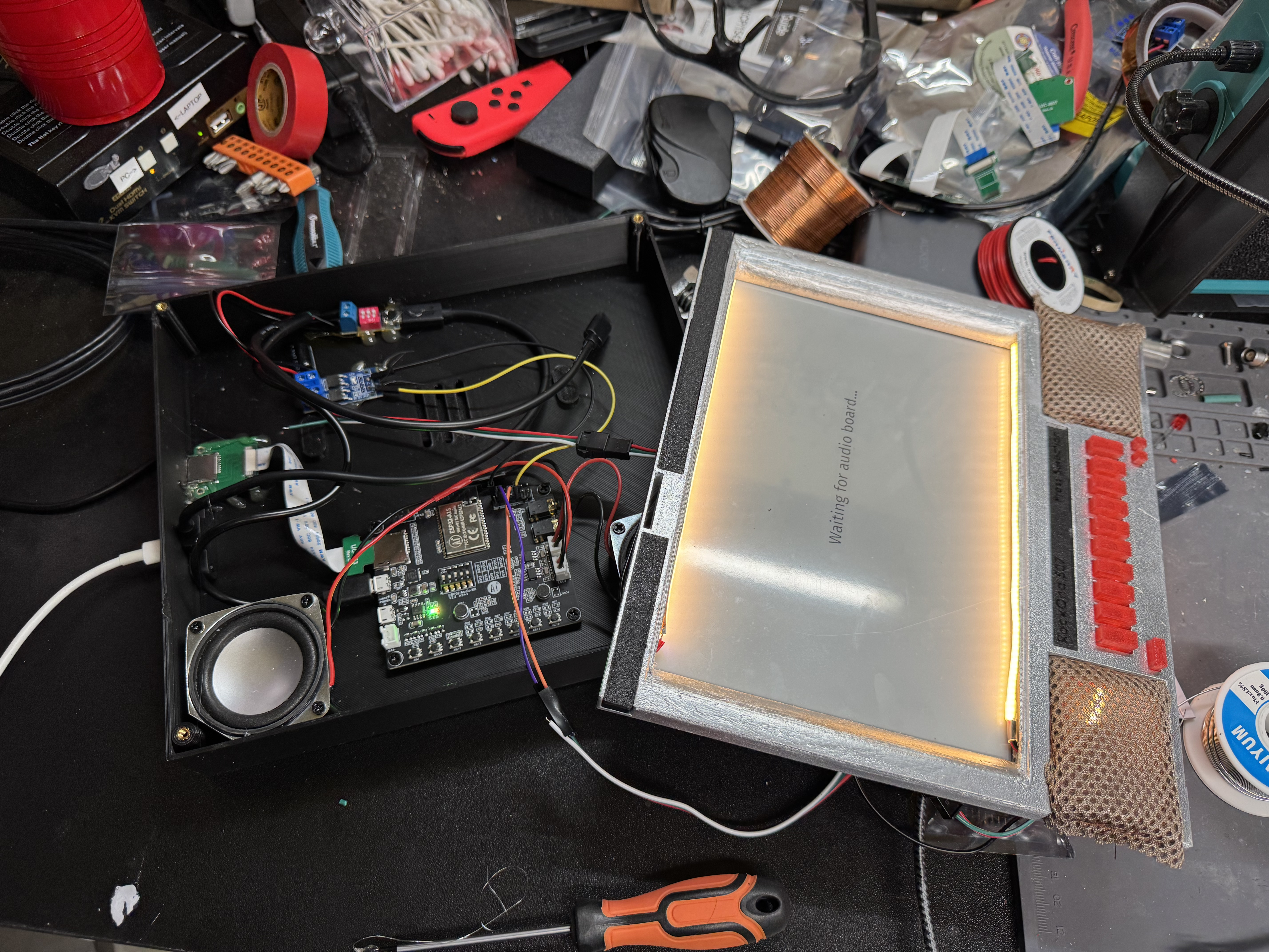
With the speakers in, and wired up, I used the heat sets and put the jukebox board in and programmed it. Then I wired that into the power sub system and connected the two ESP32s. And crazy enough, it worked! I did some tweaking from there around the buttons, and screen output, but overall, we were good!

I did have a moment where I had the IO Board ESP32 connected to my laptop, and jukebox on the normal power system, and I couldn’t get the serial line to come up. That’s when I remembered serial communication really needs 3 wires, RX, TX, and ground. I had originally planned for both ESP32s to be in the case and they would be sharing a common ground. Once I put both of them on the power from inside the case, the serial line came up!

With the project working, I went into one of the hardest parts: selecting music to add. While selecting music, I would let it play in the background. Working hands on with it I realized I wanted to add features like a queue to the screen and some feedback about which buttons you have pressed.

Wrapping Up

This project had me using a bunch of engineering things I hadn’t done before. Two ESP32s working together, working with a PCF8575 port expander, 3D printing then priming, and painting to try to get good chrome, MOSFETs, E-Ink; it was a lot of fun.

I also had ideas that could go into another version down the line: a knob on the side like the original to have more than one page of songs, a web interface for uploading songs and showing the queue, Spotify connect support (somehow). Possibly a cheaper version where you print out the song list and don’t need an E-Ink screen. I want to use these units for a while in my office and in the workshop, and then see what makes sense to add over time.

If anyone has any questions or is interested in making one and needs more information than I have here and in the repo let me know!

Homelab Token Ring

For the LAN Before Time, my retro rack, I wanted to mix the most diverse set of CPU/OS/Networking I could find. There are not a ton of networking standards out there, as Ethernet took over so quickly. One that has always interested me is Token Ring, IEEE 802.5 standard, mostly from IBM as a competitor to Ethernet. Token Ring went through many transitions in its time on the scene, from speed changes to connector changes, lasting from the mid 1980s through the 1990s.

Connectors

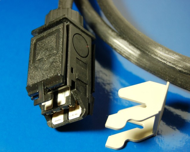
Photo creative commons from Wikipedia

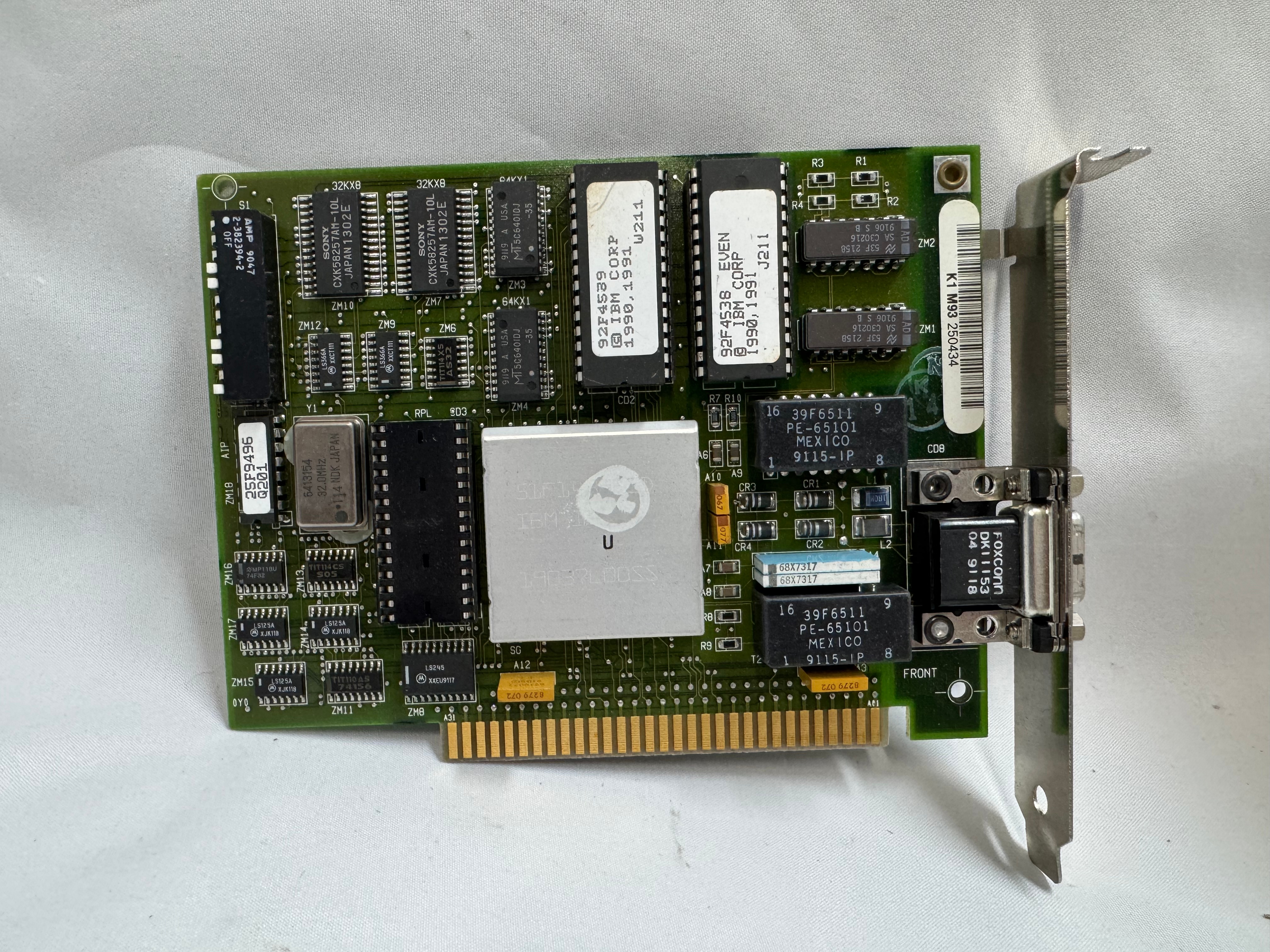
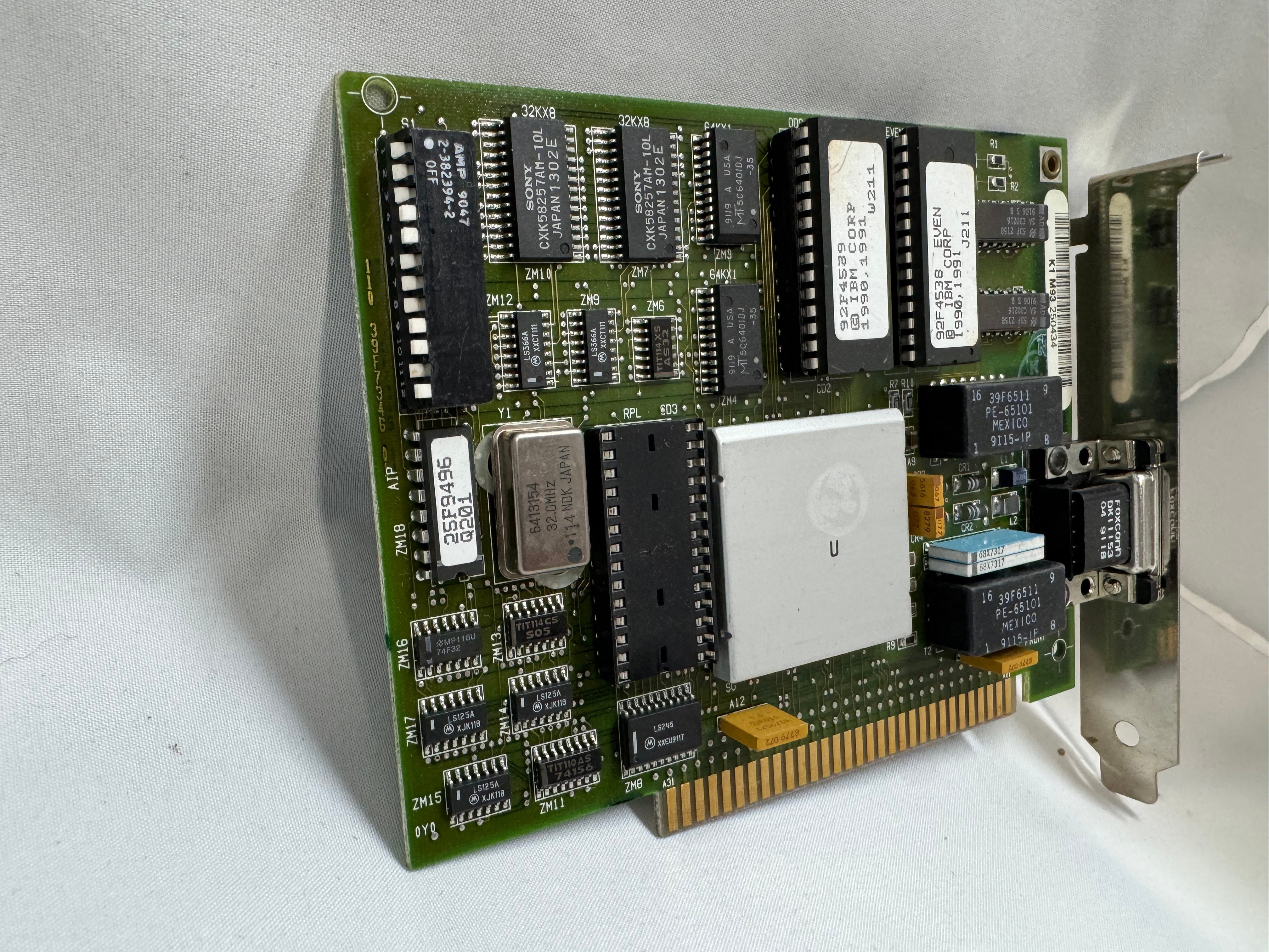
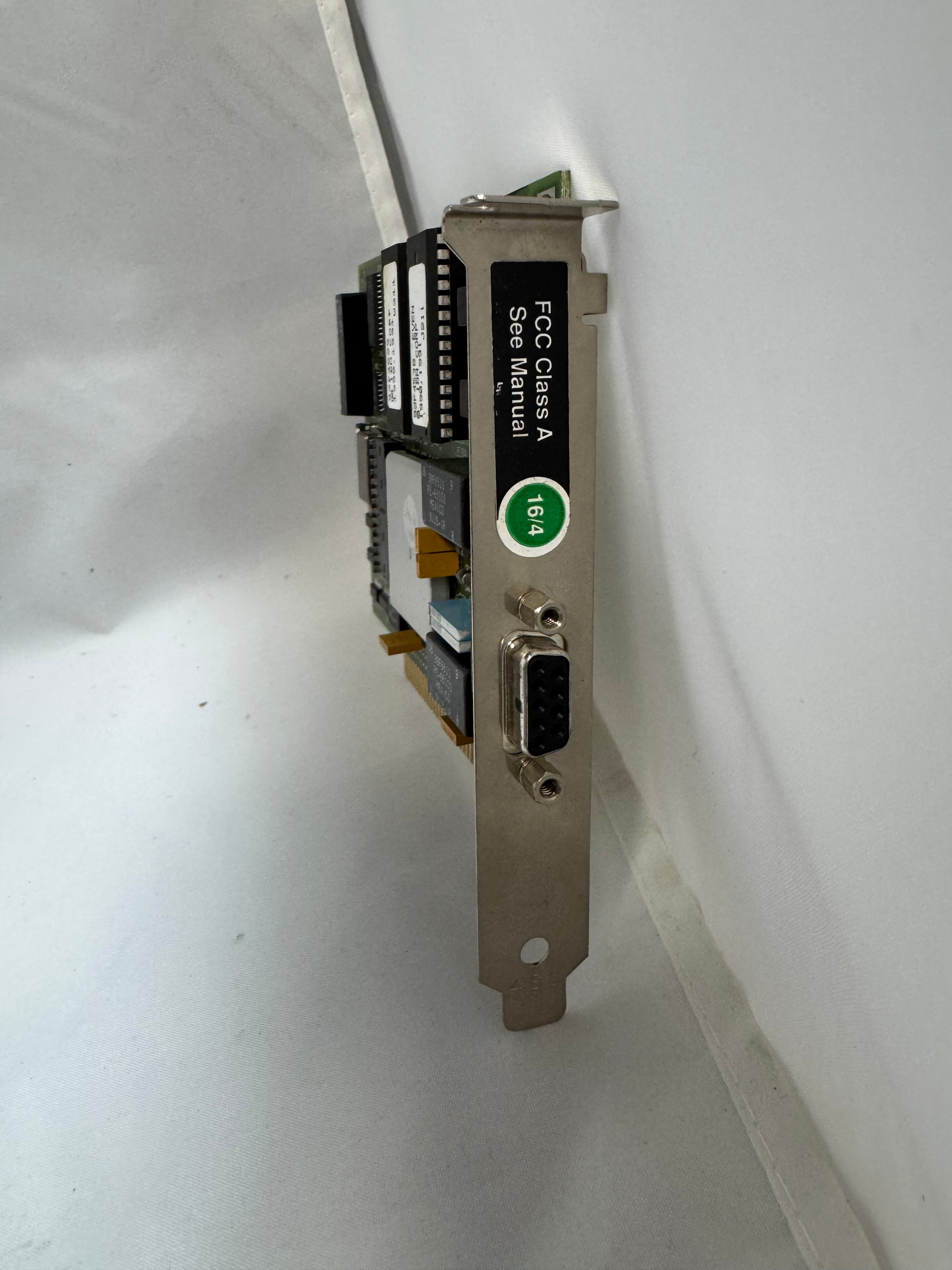
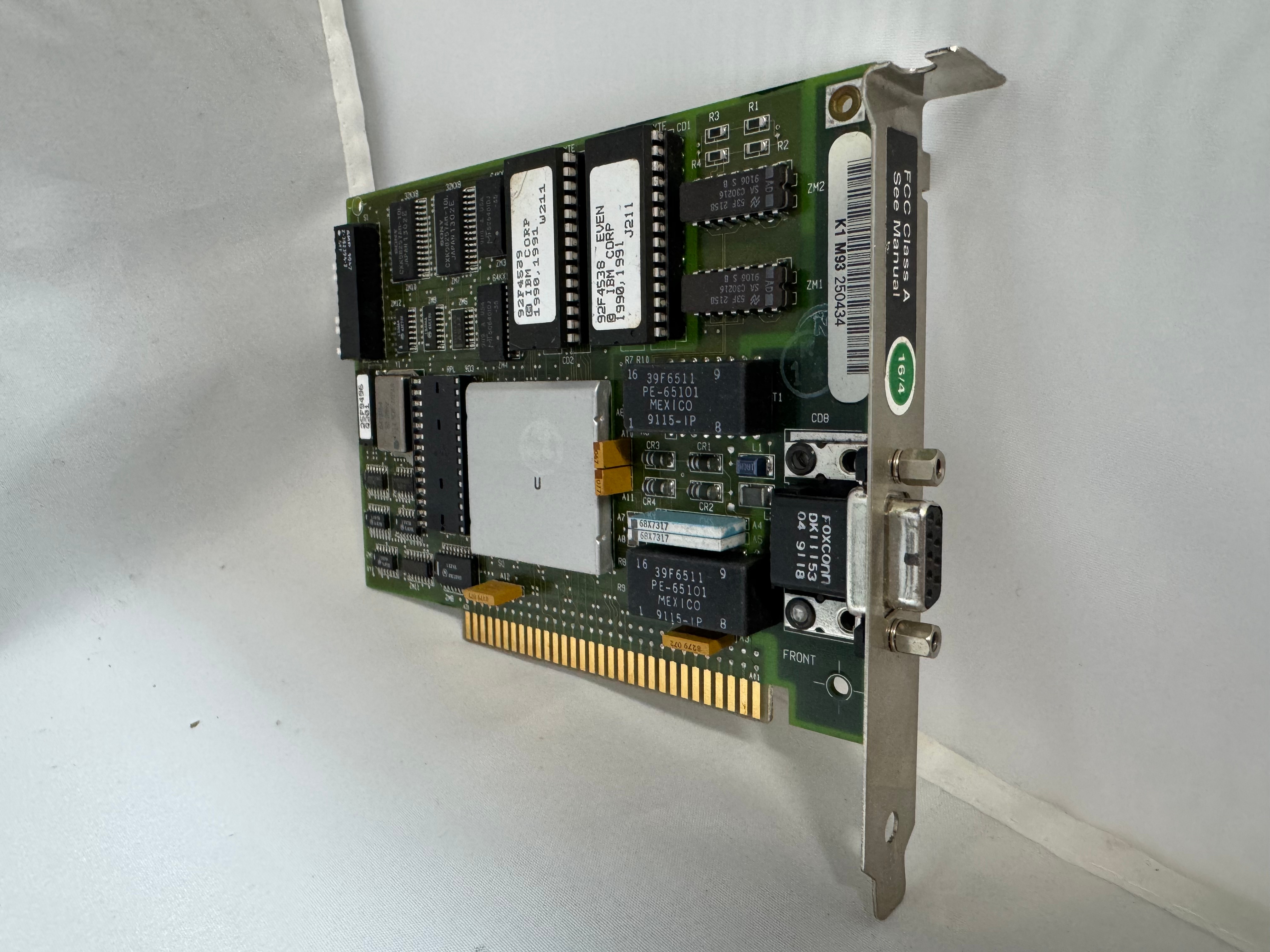
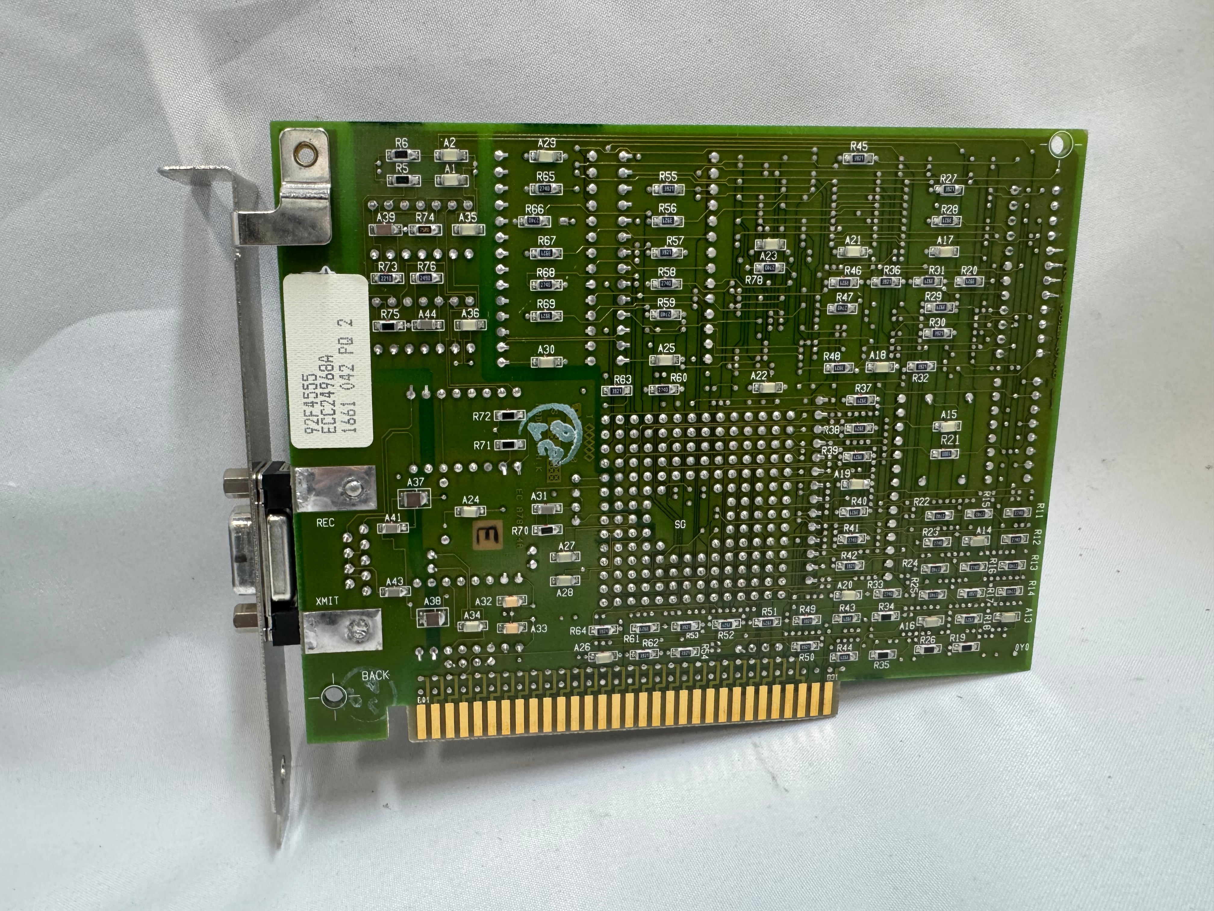
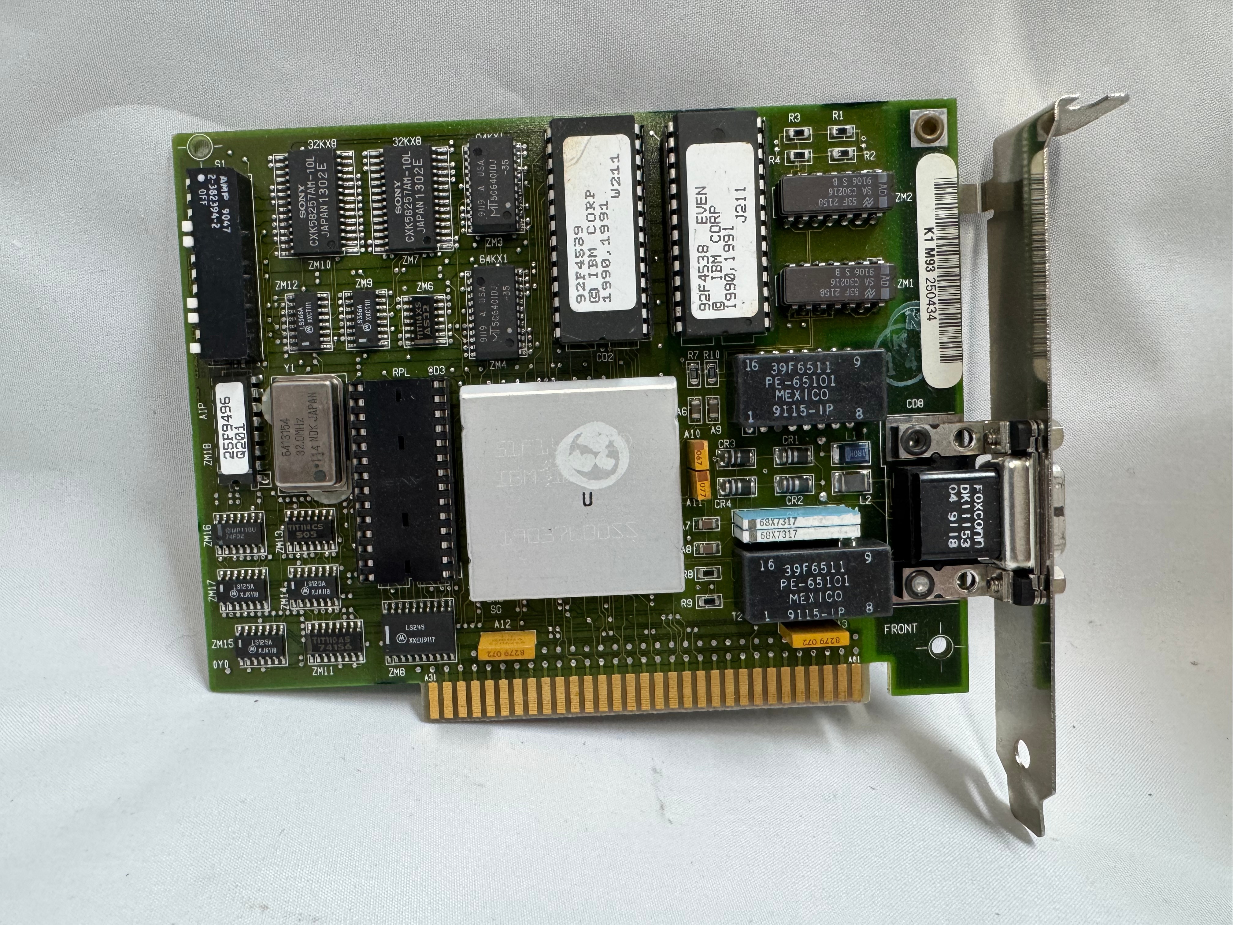
The protocol started at 4mb/s (megabits a second), with the computer having a DB9 connector going to a giant 4 pin plug.
Later 16mb/s was added. Most of the cards you will find are 4/16 cards.

The physical connector, and connection speed are independent, you can use either the DB9 or RJ45 connectors to run 4mb/s or 16mb/s.

The cards started in the ISA era and later continued into the PCI era. The connector also evolved to a standard RJ45. There were adapters to go between the older connectors and newer ones. Later cards would include both DB9 and RJ45 connectors. With RJ45, only the middle 4 pins were used, but in a straight through way, allowing normal Ethernet straight through cables to be used.

In the last updates to the protocol, 100mb/s Token Ring was added, but by the time that came out Ethernet had taken much of the market share. And finally in 2001 a 1000mb/s standard was created, but Wikipedia says no devices ever came out for it.

MAUs

Unlike Ethernet, Token Ring cannot connect two computers directly. You need to go through a Media Access Unit, or MAU. These units control ports going in and out of the ring. They can be thought of like an Ethernet hub or switch. The Token Ring itself also needs a terminator on it. Later models contained internal terminators if put into a specific mode. There are MAUs with the old large IBM connector, and there are newer ones with RJ45. There were adapters between any of these connection types for networks in transition.
My MAU Journey

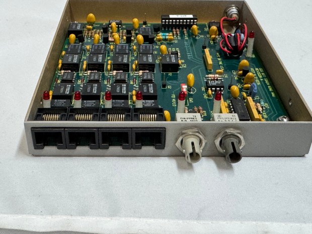
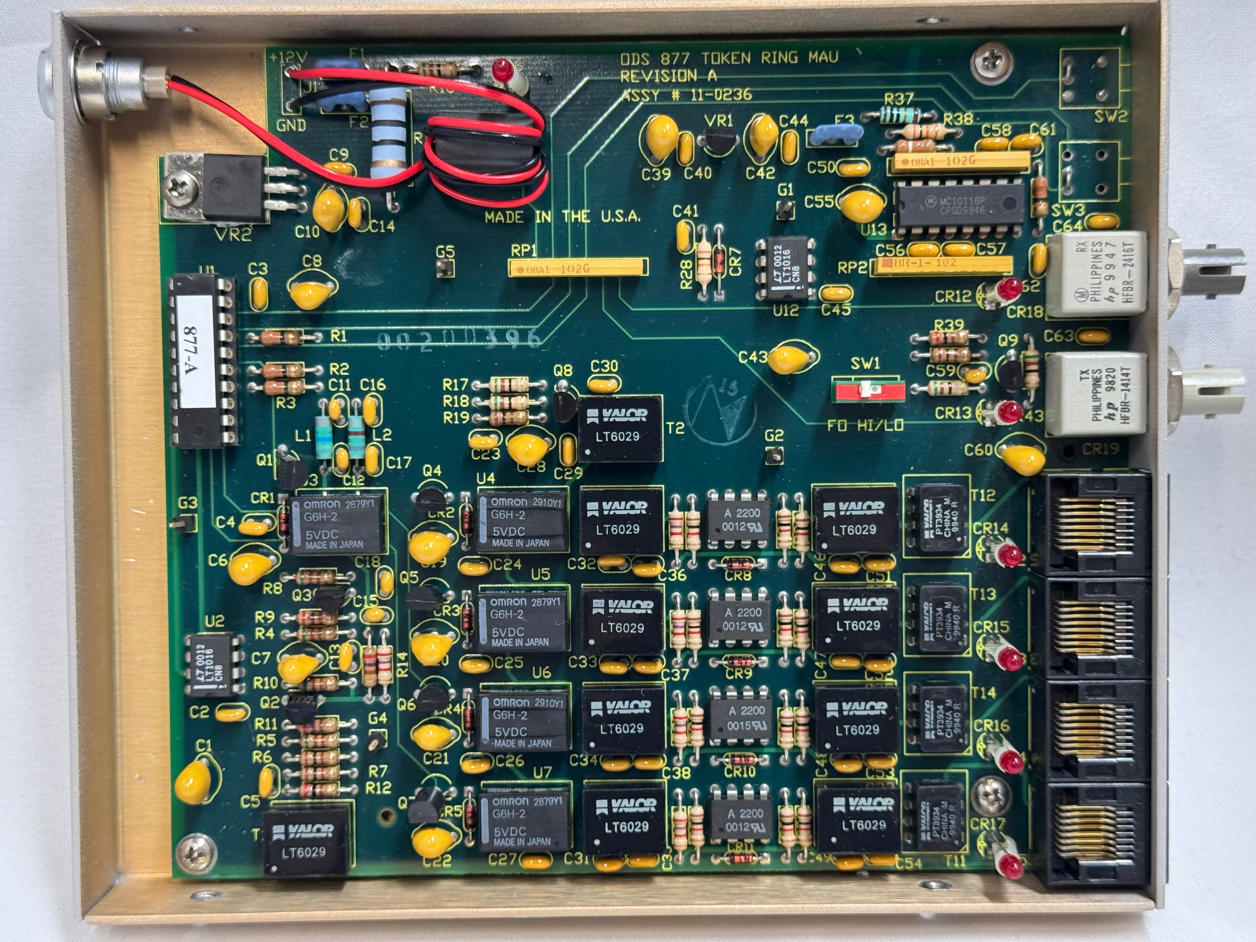
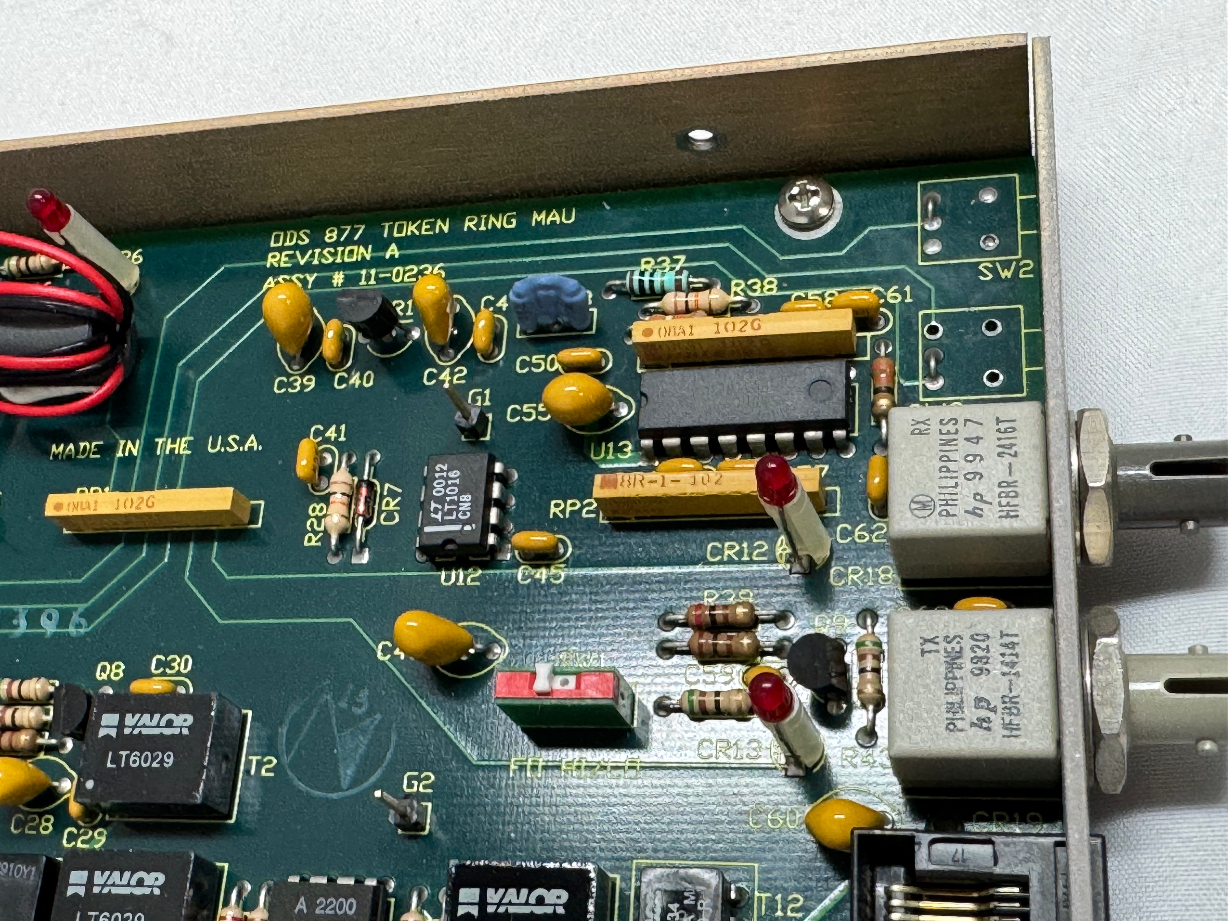
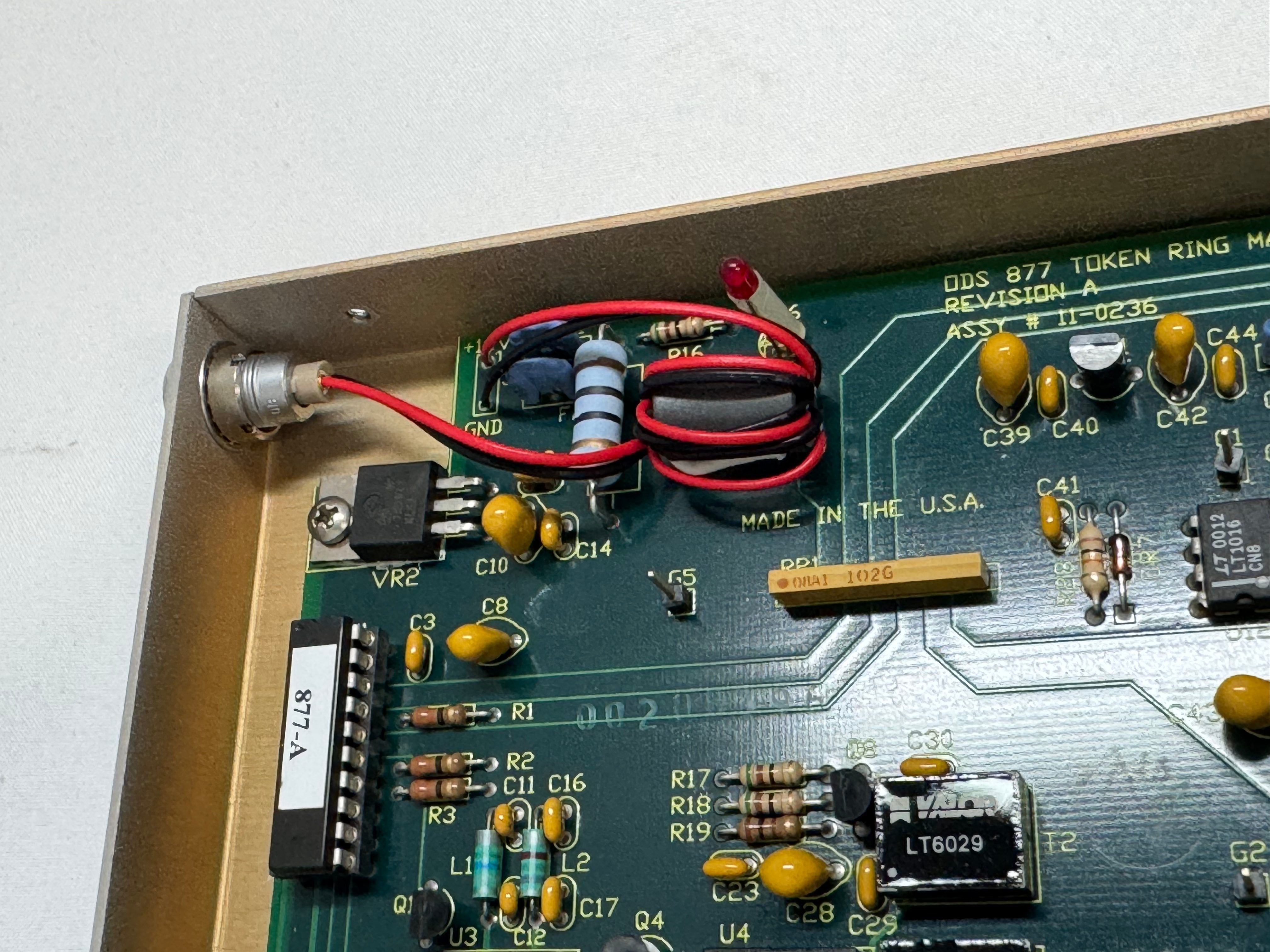
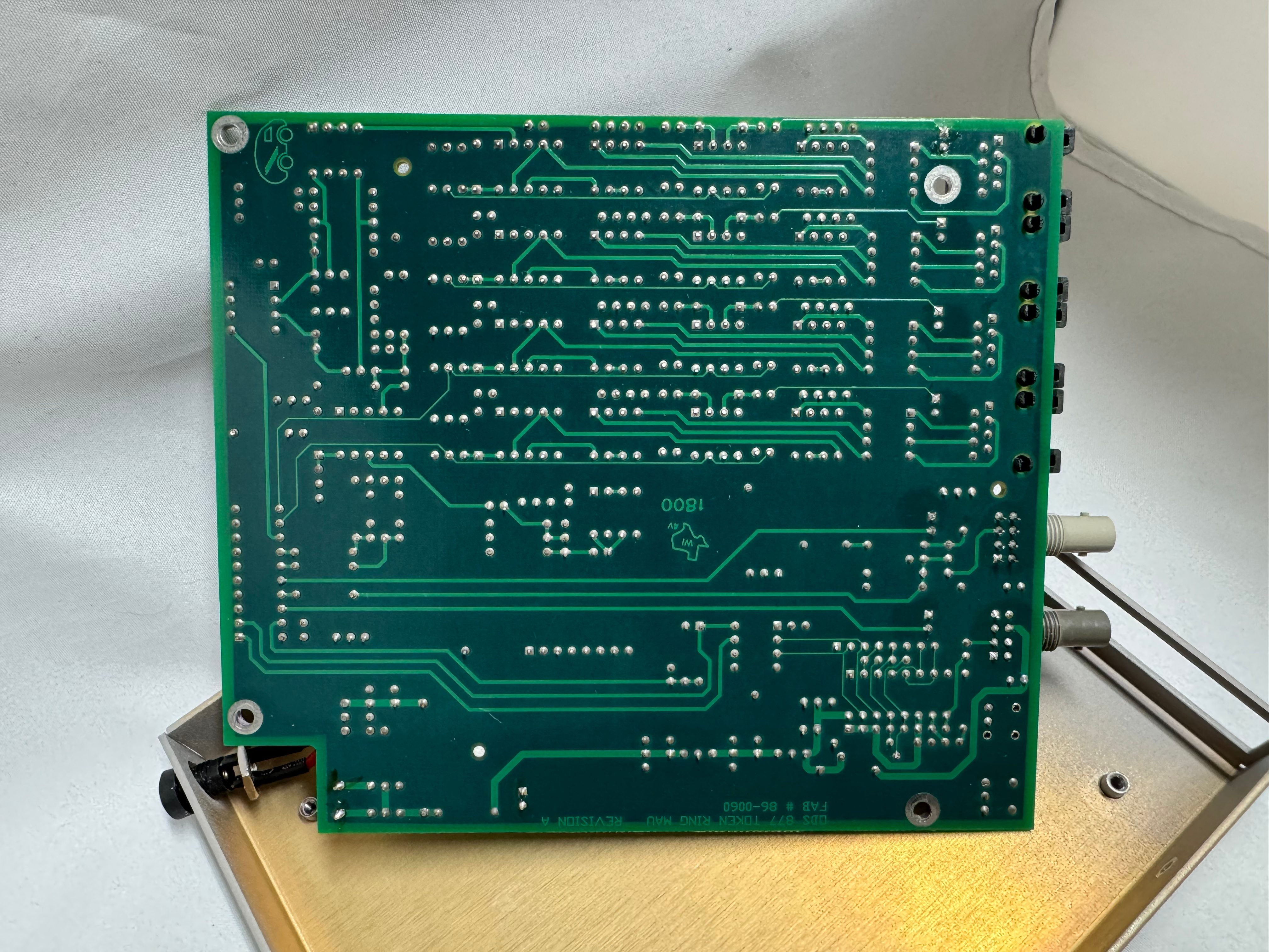
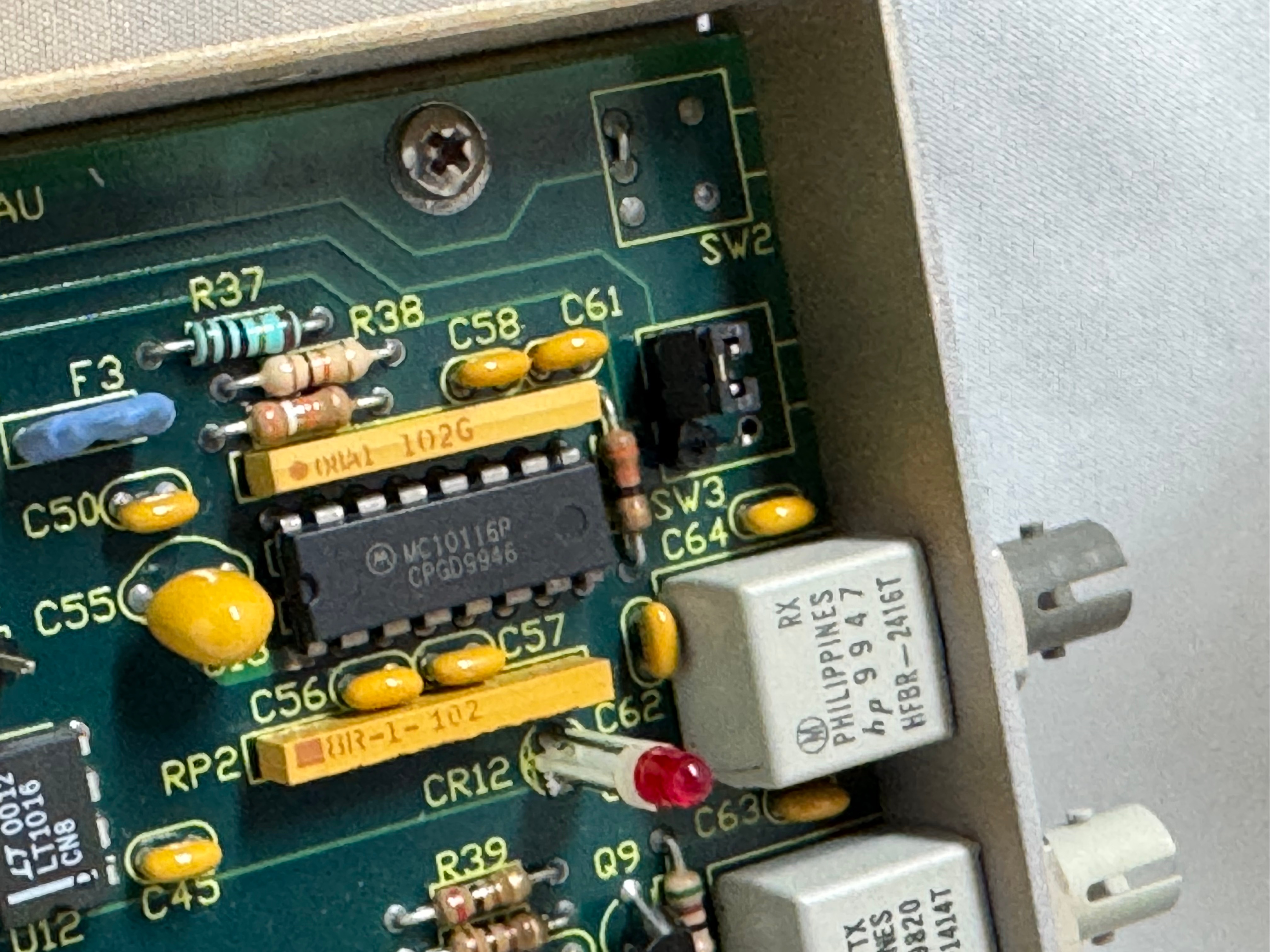
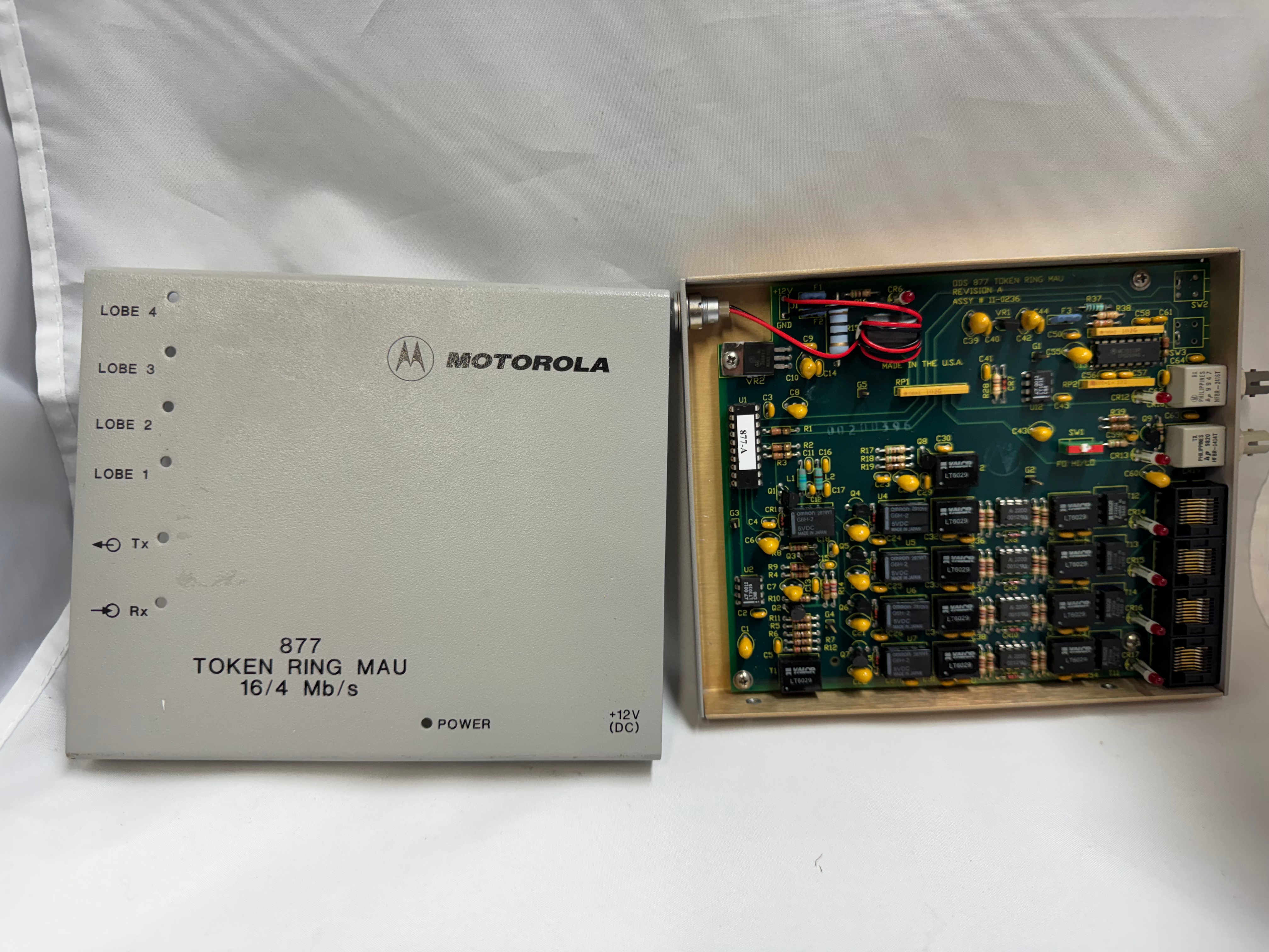
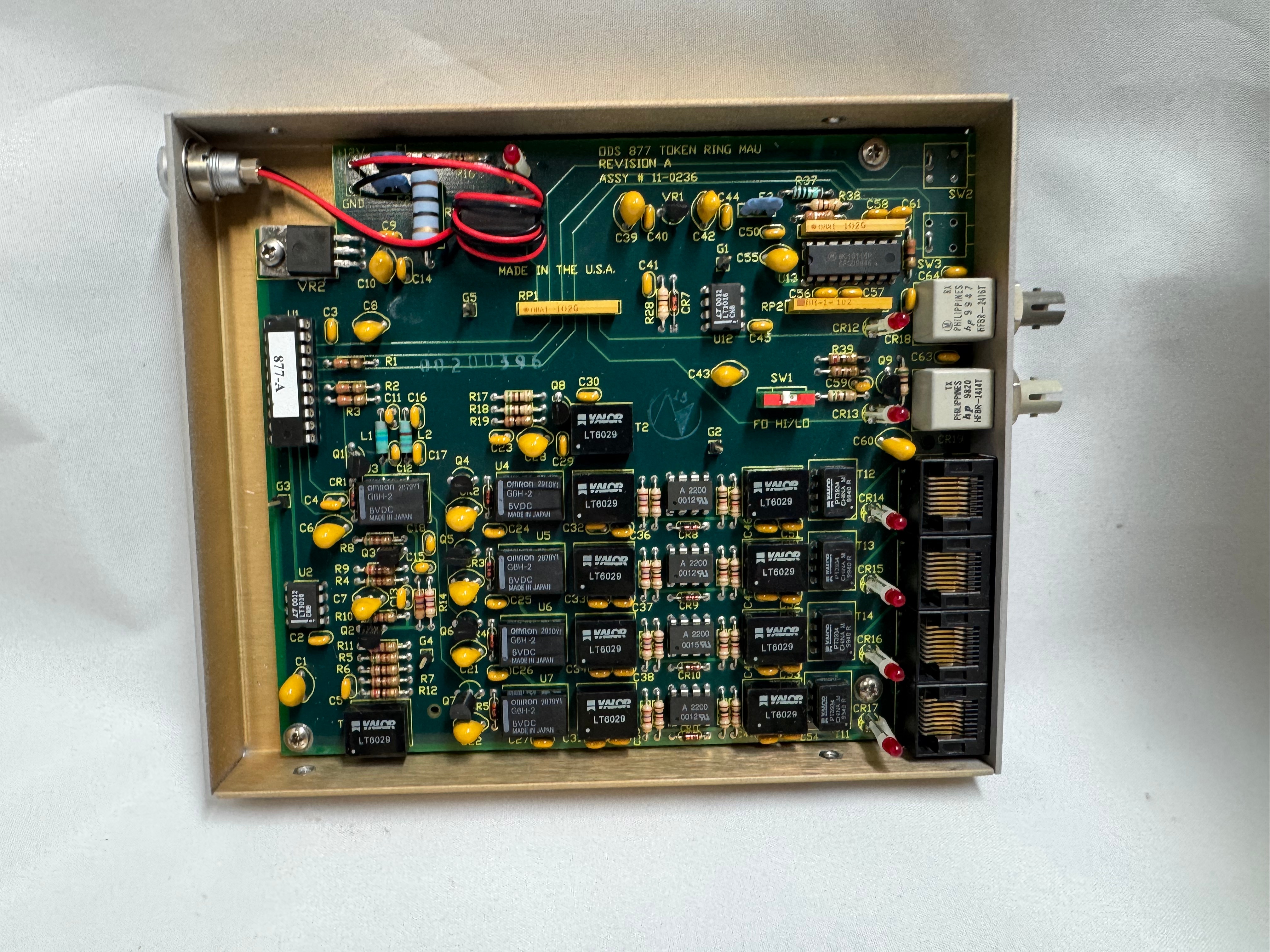
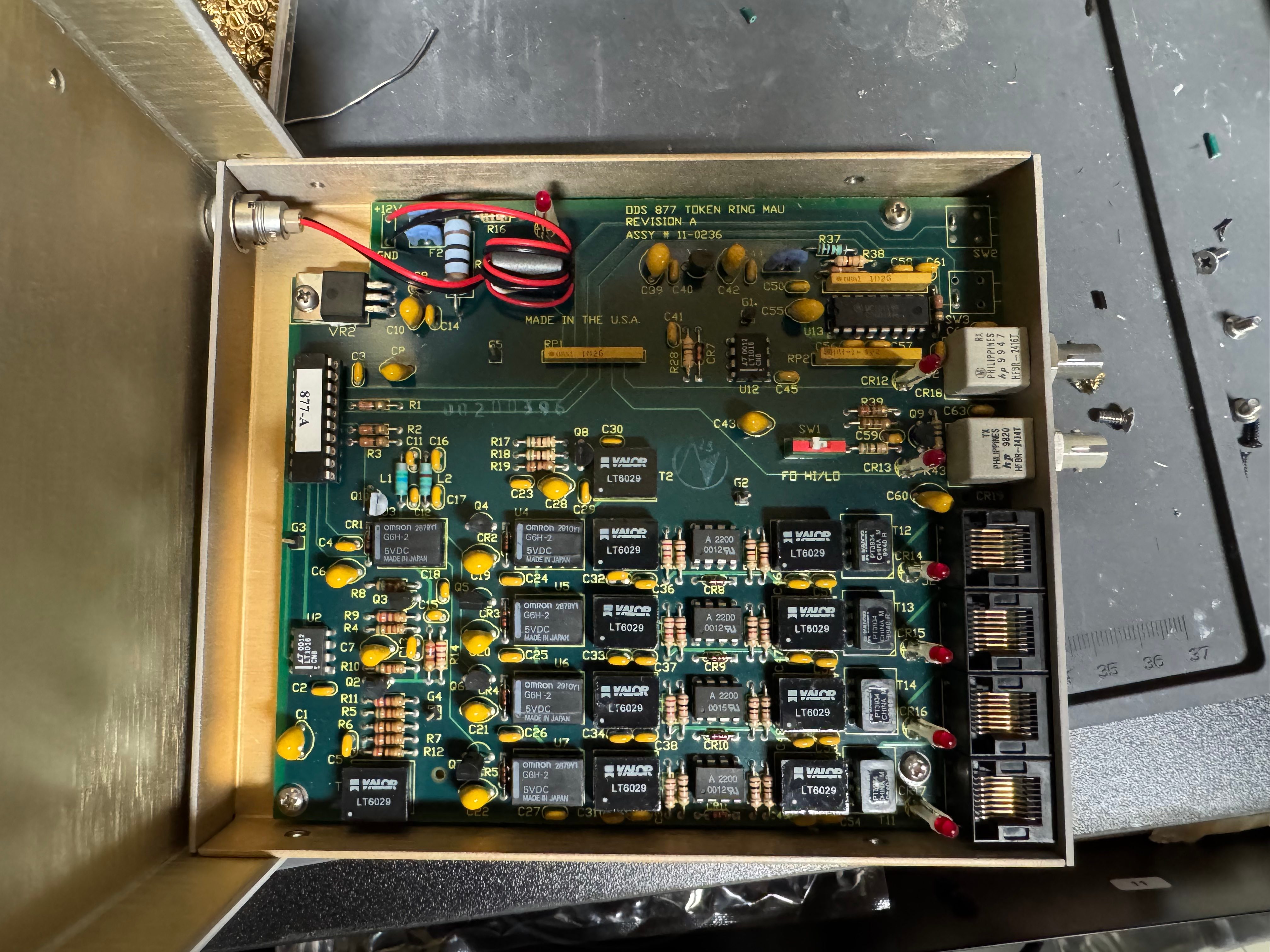
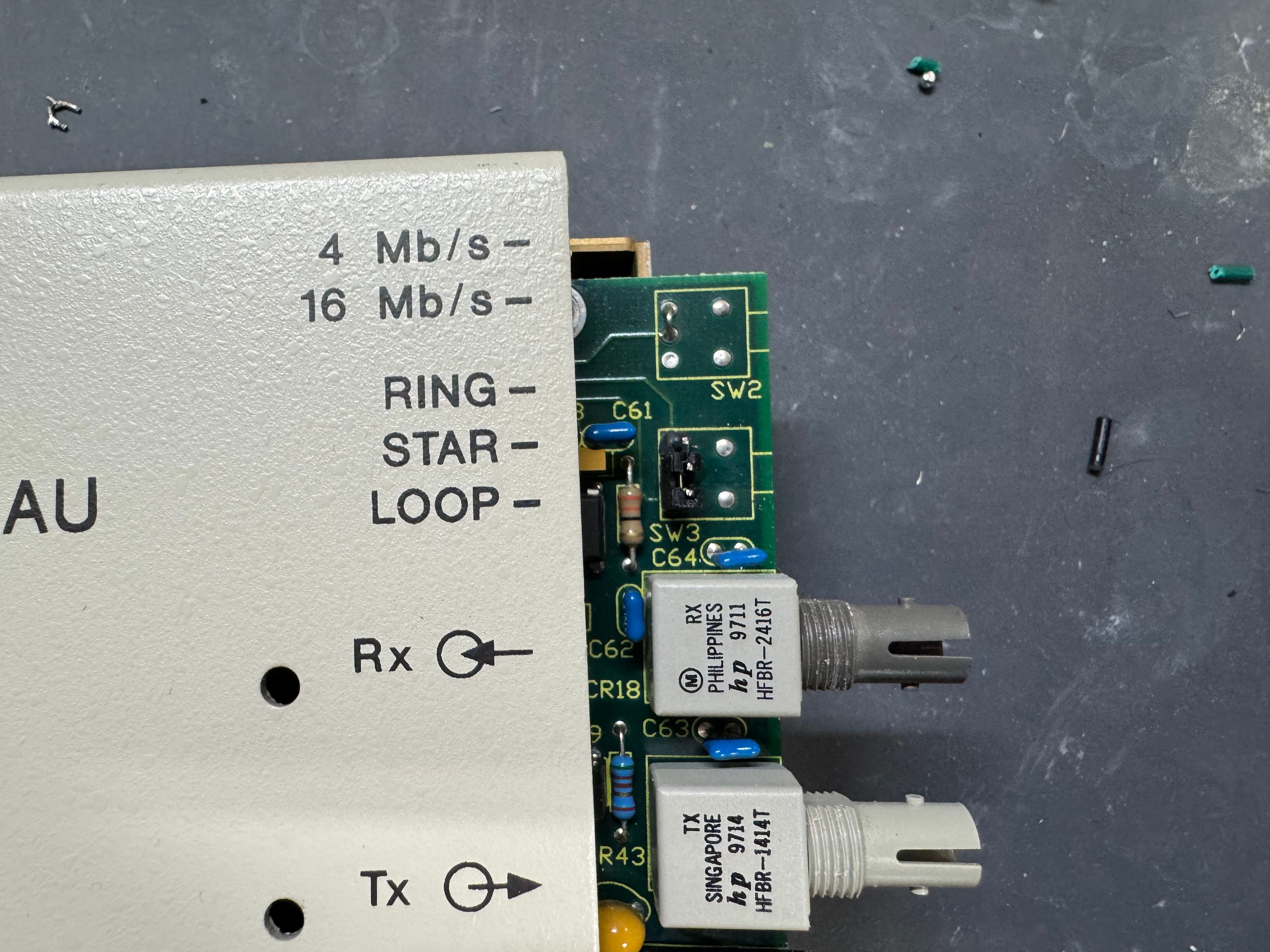
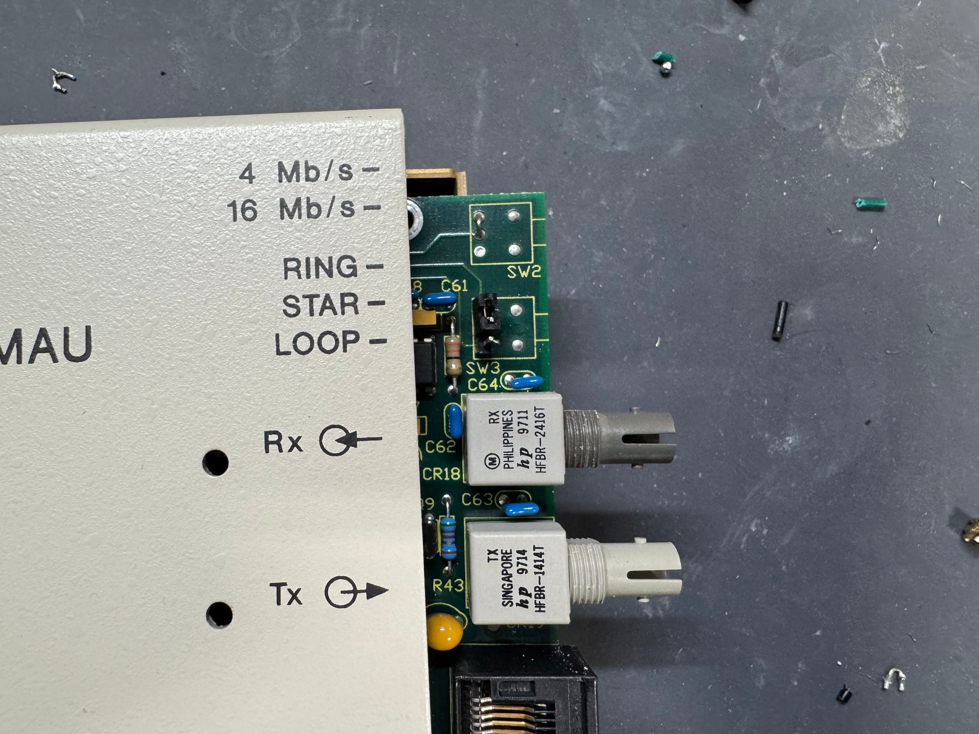
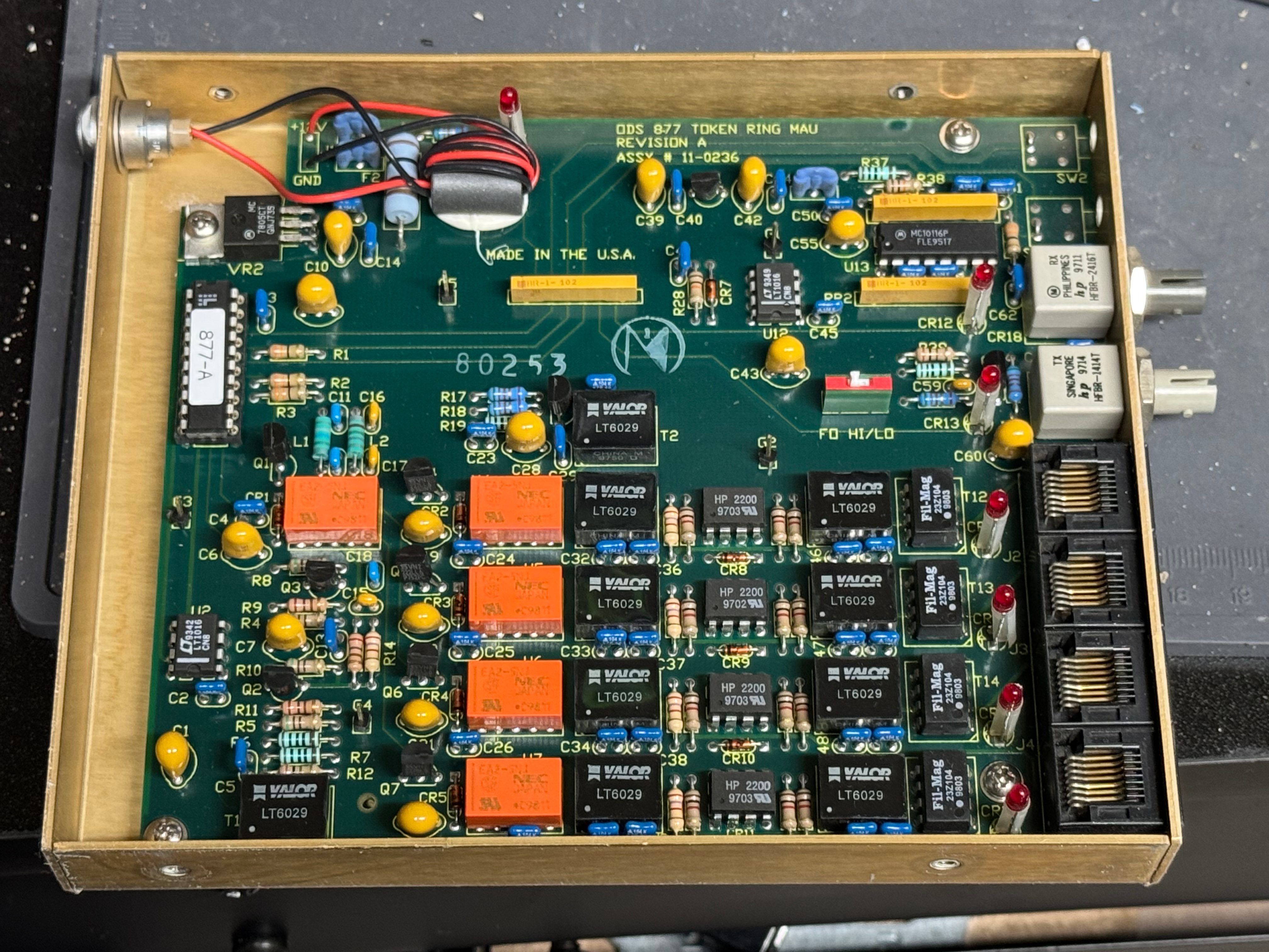
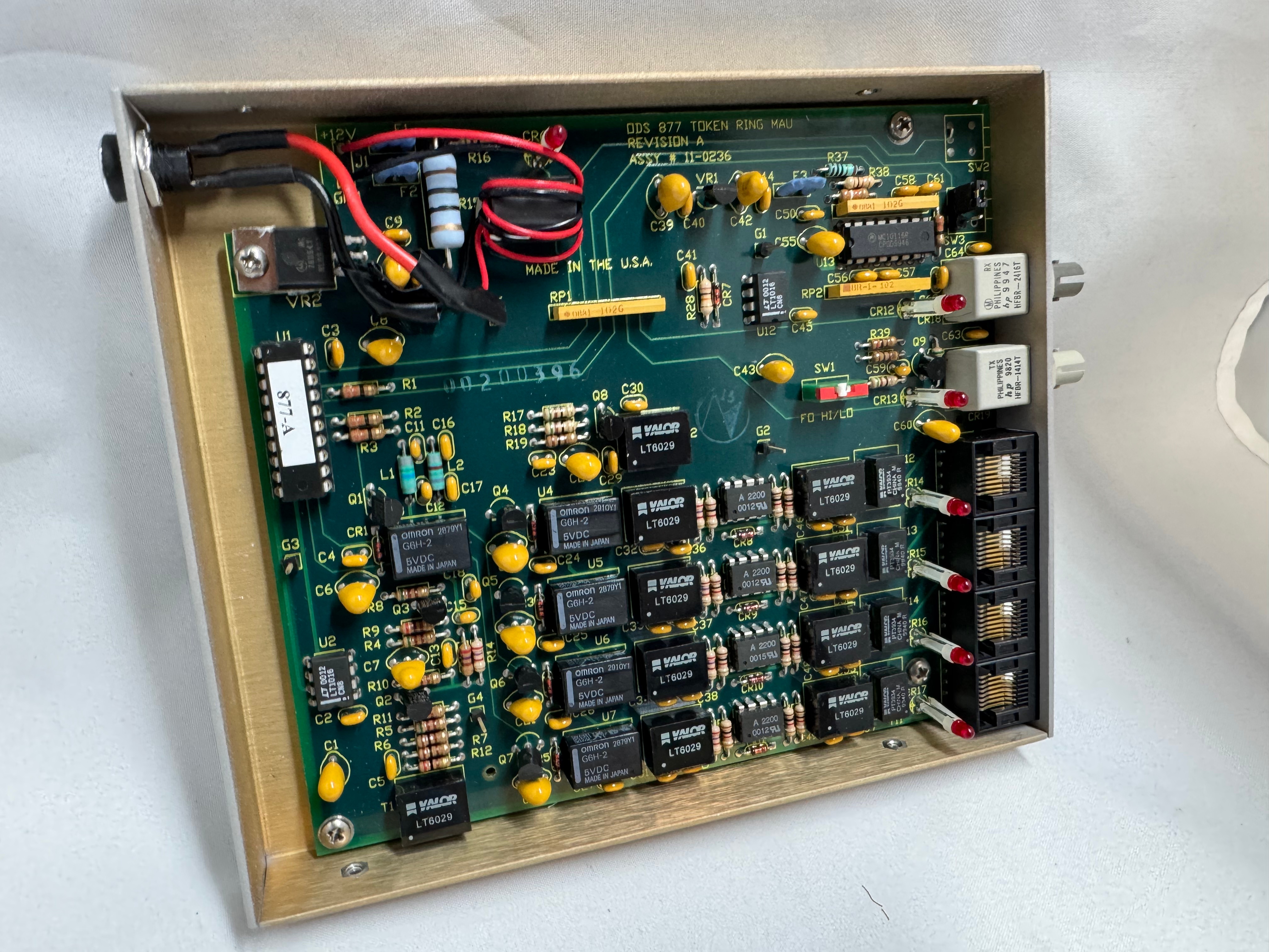
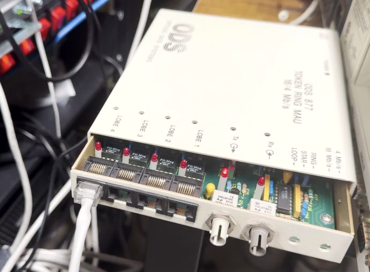
I picked up 2 of the same model MAU. ODS/Motorola 877. These are great units after some hardware tweaks and I would recommend them. While they are the same model, and same firmware revision, Motorola bought the company ODS (Optical Data Systems) which made them. The first one I got has ODS branding and a spot for two switches to control the mode and speed of the MAU. The second one is Motorola branded on the case, but not the board, and is missing the cut out in the case for switches.

From what I can learn with working on it, looking at documentation for other MAUs, and Claude; the device can work in three modes:

  • RING: Normal Token Ring operation, requires external RI/RO loopback cable to close the ring, use this when daisy-chaining multiple MAUs together, all active lobe ports are part of the ring.
  • STAR: Each port operates independently (not a true ring), used for certain troubleshooting or special configurations.
  • LOOP: Internally connects Ring In to Ring Out, self-terminates the ring without external cables, perfect for a single standalone MAU.

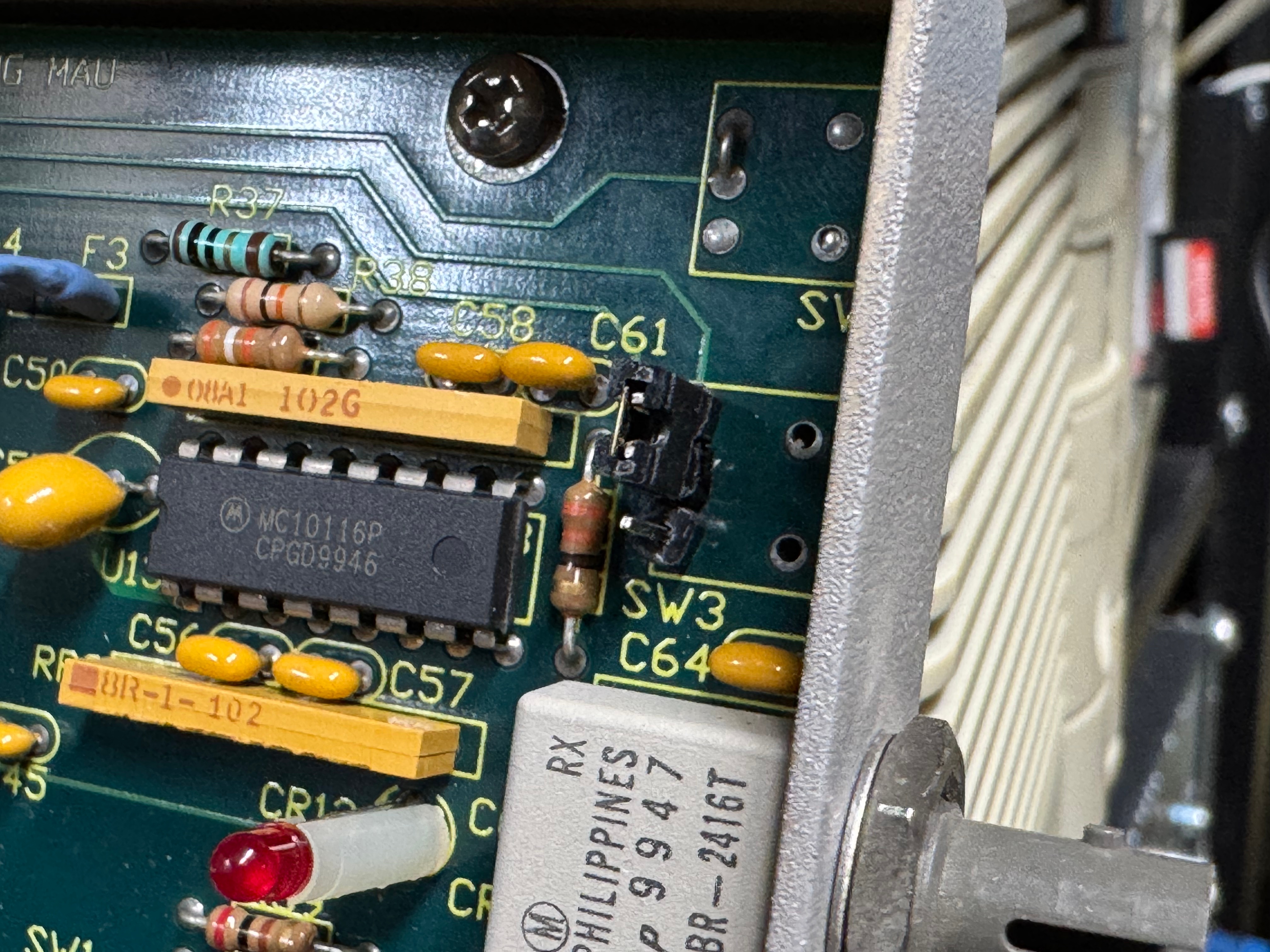
The MAUs were designed to have a switch to go between modes. Neither of mine did, both had a physical soldered in jumper setting their mode. The Motorola one didn’t have a hole in the case for a switch to exist, but the PCB is the same. I removed the soldered jumper and replaced it with a standard PC jumper pin, that way I could easily change it when I wanted to. In the end I will leave them both in LOOP mode most of the time, that has internal termination and is used for simple 4 port usage. Bridging the top and middle pin put it into LOOP mode, which is what I needed. Before that it was in RING without termination; each device would join the ring for 10 or so seconds, not hear anything else on the ring, and then disconnect. This MAU appears to be able to automatically go between 4mb/s and 16mb/s mode and I never moved the speed jumper.

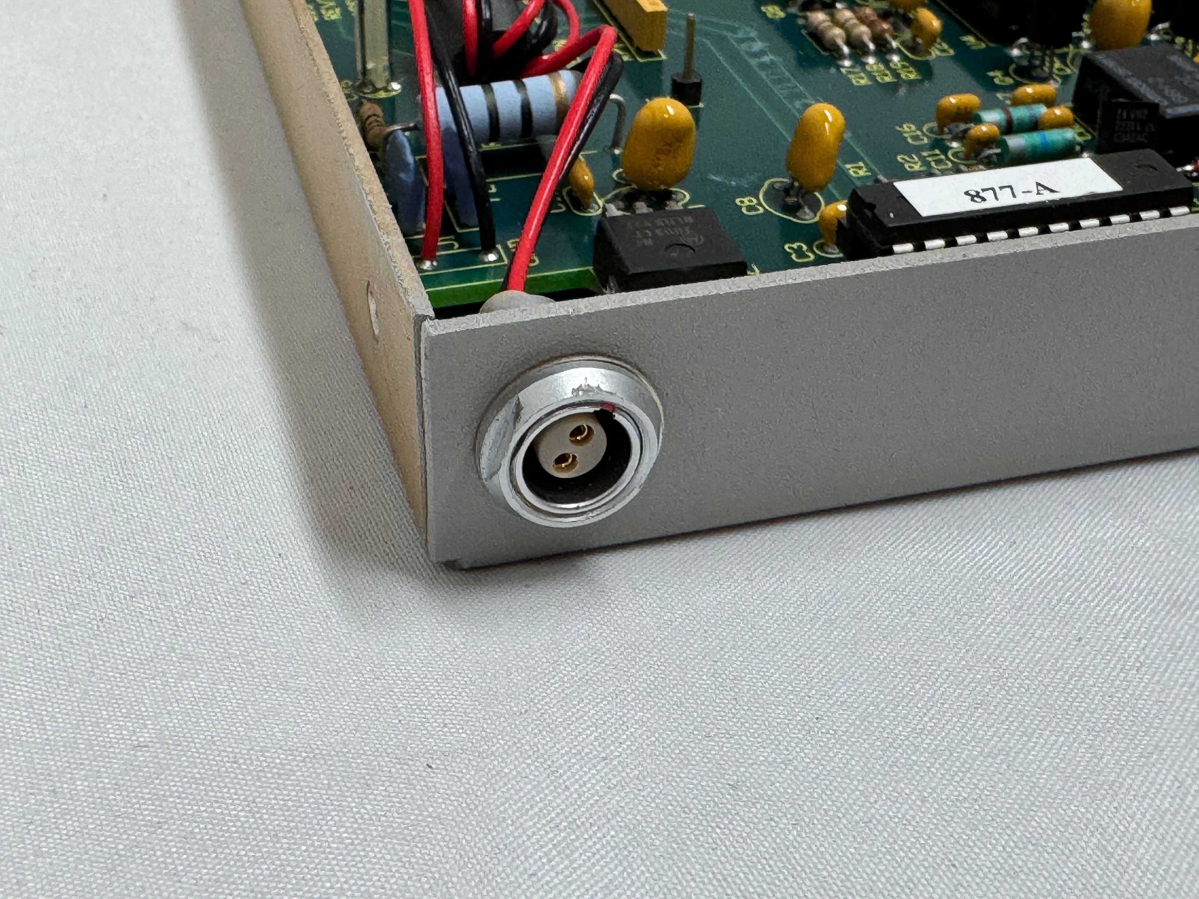
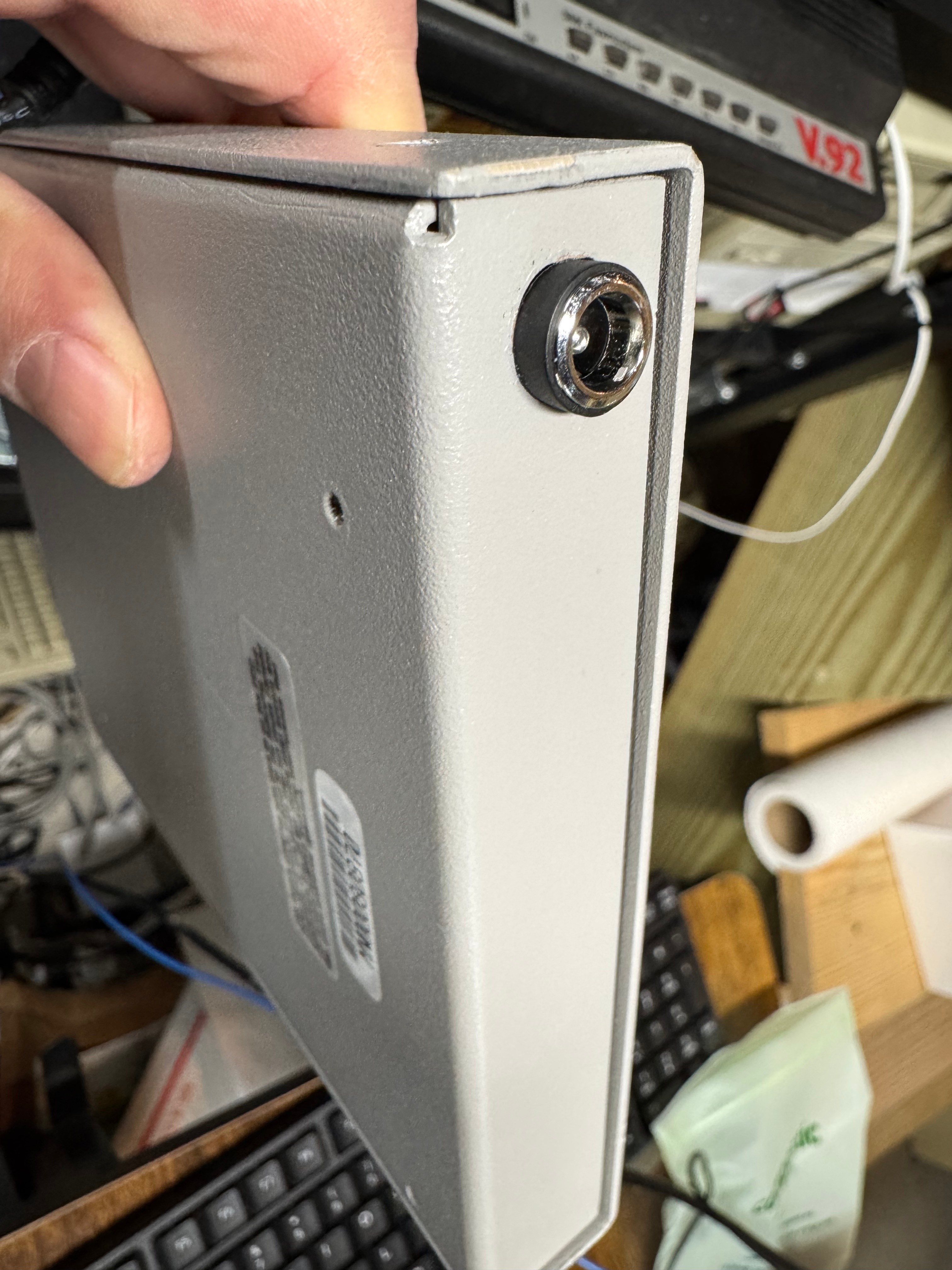
The two modifications I made to these devices were the mentioned jumper change; and they come with a FGG 2P power connector onto a RJ45 plug. It says it needs 12V on it, and I wanted to just be able to use a wall plug, I first tried to get that connector, but after finding it tiny and hard to work with, I replaced the port in the device with a standard barrel plug.
Token Ring Drivers

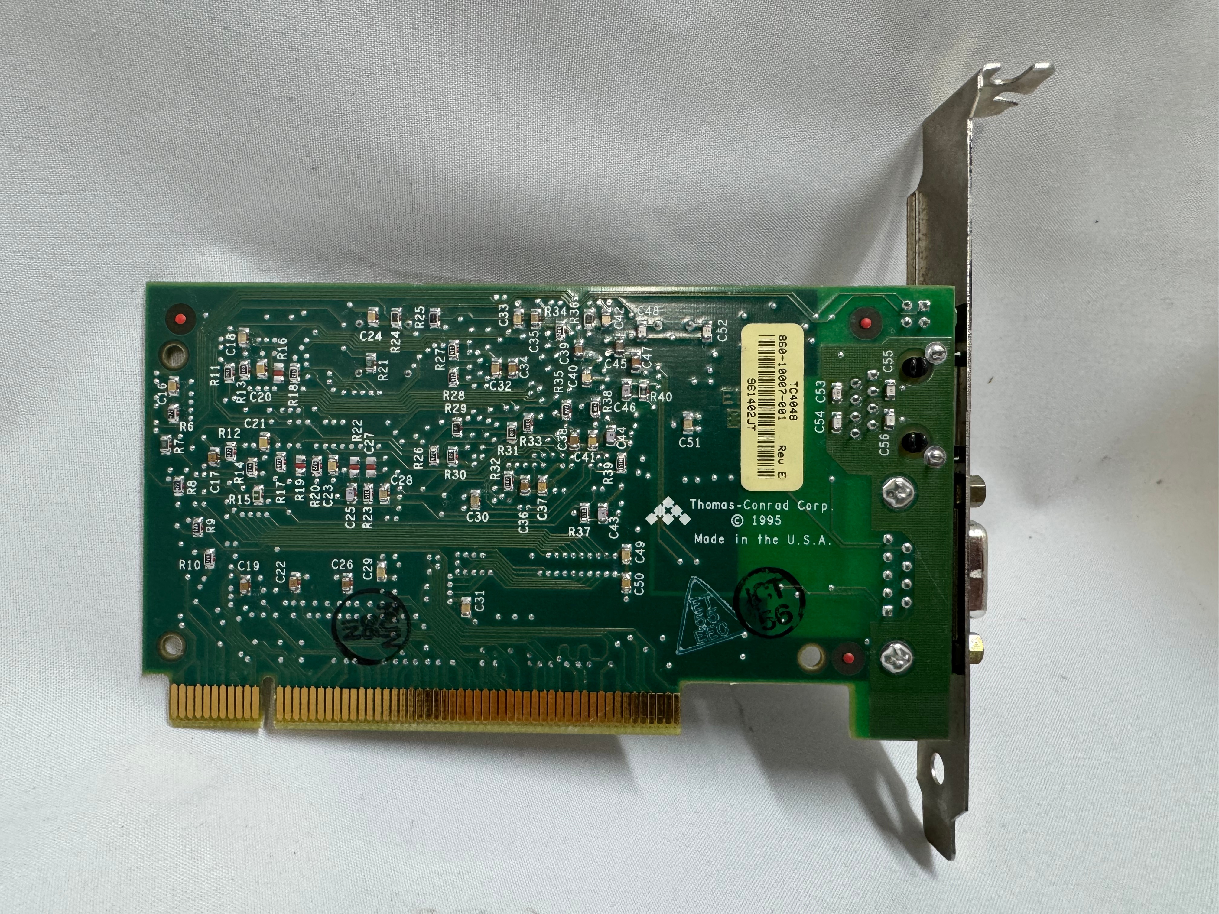
One difficult part of finding Token Ring cards on eBay, you never know if you can find all the drivers. The card I have is a later model PCI card. It’s a Thomas Conrad TC4048. Thomas Conrad seems to have been an interesting company putting out different network cards over the 80s and 90s before ethernet took off. It is easy to find their Token Ring and Arcnet cards online. Finding their drivers on the other hand, proved to be difficult.
Driver Hunting

I found https://archive.org/details/pwork-297 this archive.org ISO, it contains a TON of drivers for devices in the 90s. It lists TC4048 as one of them. I download the image, install the driver AND… Windows 98 says it has the tc4048 files it needs except a “tc4048.dos”. I then found https://www.minuszerodegrees.net/software/Compaq/allfiles.txt this site which has every HP/Compaq driver that used to be on their site. Those are much easier to search. There were several TC4048 items.

I found an archive at https://ftp.zx.net.nz/pub/archive/ftp.compaq.com/pub/softpaq/sp19501-20000/, and downloaded sp19859.exe, which expanded and had “DOSNDIS” and “OS2NDIS”. I knew Compaq rebranded this card, so I yoloed and renamed “DOSNDIS/CPQTRND.DOS” to “tc4048.dos” and put it with the drivers I got from the archive.org image. The Thomas Conrad drivers from different vendors had similar files with different names, but they were the exact same size, and appeared to be the same… I hoped it would just work if I renamed a file from a different vendor to the one I needed. I made progress with error messages now seeing “svrapi.dll” missing in C:\Windows\, and found that file in C:\Windows\System32… and just copied it up one directory…

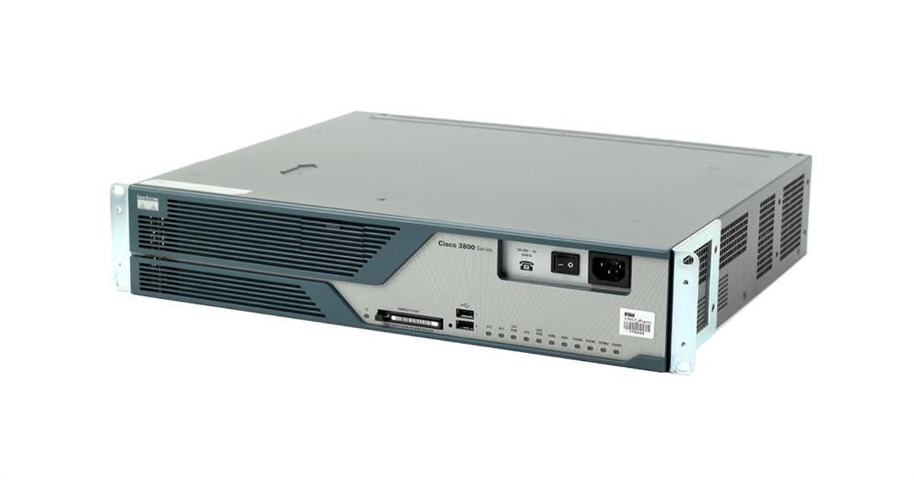
And magically that worked! I had a 16mb/s connection working between the Cisco 3825 (core) and the Windows 98 PC (edge)! The core of my retro network is a Cisco router. I purchased this Cisco 3825 system a while back because it’s the last one that supports Token Ring, but new enough to have 1gb/s uplink port to my core network. This allows me to host some retro VLANs internally, and firewall them off for security (since none of these systems have gotten patches for decades). I can play with Novell Netware and host a file share of games for the retro systems on this network as well. Using even legacy networks to move files is still a lot easier than a ton of floppy disks. I leave this router off most of the time because it’s a bit power hungry and loud. I have written about it before, and it also hosts my dial up connections.

I now had the Cisco 3825 with a Token Ring card and Windows 98 PC joining a Ring and communicating! I have watched a bunch of clabretro’s videos on Token Ring, and I saw the same issue with the Thomas Conrad drivers that he saw with his cards, Windows joining a Token Ring network and the drivers have an odd interaction. When the computer boots, at that point it tries to join the ring, the system will stay at the Windows startup screen an extra-long amount of time as it tries to enter the ring. The system will also wait at shutdown as it attempts to leave the ring. If the Token Ring card is not plugged in, you get a message about failing to connect after a prolonged startup.

Future Token Ring Plans

I plan to play with Token Ring a bit more both as a standard networking technology alongside the Ethernet network I have. Now that I have two working MAUs I want to experiment with linking them over the ST fiber connectors they have and getting a Token Ring connection over fiber. I am pondering learning FPGAs by building a Token Ring to Ethernet bridge using an FPGA connected to an ISA Token Ring card. I just find it interesting and it would push my FPGA skills; the project would need to translate the headers of Token Ring at layer 2 to Ethernet headers.

Token Ring is the layer 1 and layer 2 technology, after that we use standard TCP/IP on top of it; this has made it easy to get started with Token Ring over another protocol like AppleTalk or IPX. Once the physical connection was up, and devices could enter the ring; I was able to use standard Cisco commands and create a routable DHCP pool for Token Ring.

Step-By-Step Setting Up Networking for Virtualization on OpenShift 4.19 for a Homelab

As we continue our Openshift journey to get virtualization working, we have a vanilla node already setup and now we need to get the networking configured. The examples here are from Openshift 4.19.17.

Networking in OpenShift is conceptually two parts that connect. The first part is the host level networking; this is your CoreOS OpenShift host itself. Then there is how do the pods connect into that networking. Usually, the network connects through your network interface card (NIC), to the Container Networking Interface (CNI), then to your pod. Here we will be using a meta plugin that connects between the NIC and the CNI called Multus. Redhat has a good post about it.

Host Level Networking

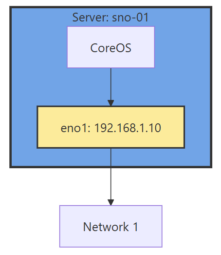
This part of the networking stack is straight forward if you are used to Linux system networking, and it is setup the same way. Treat the CoreOS node like any other Linux system. The big decision to make in the beginning is how many interfaces you will have.

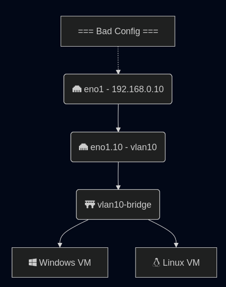
Networking diagram without sub interface

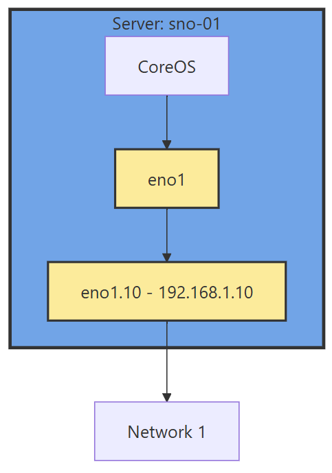
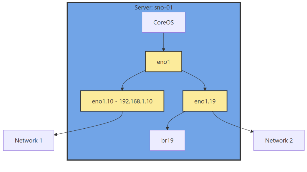
If you have 1 interface and plan on using virtualization, are you going to use VLANs? If so, then you may want to move the IP of the interface off of the primary interface and onto a VLAN sub interface. This moves the traffic from untagged to tagged traffic for your network infrastructure.

Another reason is there are bugs in the Mellanox firmware, mlx5e, where Mellanox 4 and 5 cards can think you are double VLAN encapsulating, and will start automatically stripping VLAN tags. The solution is to move all traffic to sub interfaces. You will get an error in your dmesg/journalctl of: mlx5e_fs_set_rx_mode_work:843:(pid 146): S-tagged traffic will be dropped while C-tag vlan stripping is enabled

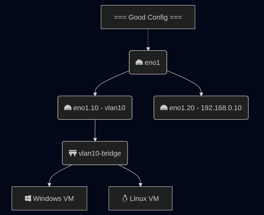
With the interface moved, that frees us up to use it for other VLANs as well. If you deployed network settings via a MachineConfig, you would have to override them there.

Networking diagram with sub interface

The rest of the configuration will be done via the NMState Operator and native Openshift.

NMState VLAN and Linux Bridge Setup

NMState is a Network Manager policy system. It allows you to set policies like you would in Windows Group Policy, or Puppet to tell each host how the network should be configured. You can filter down to specific hosts (I do that for testing, to only apply to 1 host) or deploy rules for your whole fleet assuming nodes are all configured the same way. It’s possible to use tags on your hosts to specify which rules go to which hosts.

NMState can also be used to configure port bonding and other network configurations you may need. After configuration, you get a screen that tells you the state of that policy on all the servers it applies to. Each policy sets one or more Network Manager configurations, if you have multiple NICs and want to configure all of them, you can do them in one policy, but it may be worth breaking the policies apart and having more granularity.

Another way to go about this section, is to SSH into each node, and use a tool such as nmtui to manually set the networking. I like NMState because I get a screen that shows all my networking is set correctly on each node, and updates to make sure it stays that way. I put an example below of setting up port bonding.

  • Go to the OpenShift web console, if you need to setup OpenShift I suggest checking out either my SNO guide or HA Guide.
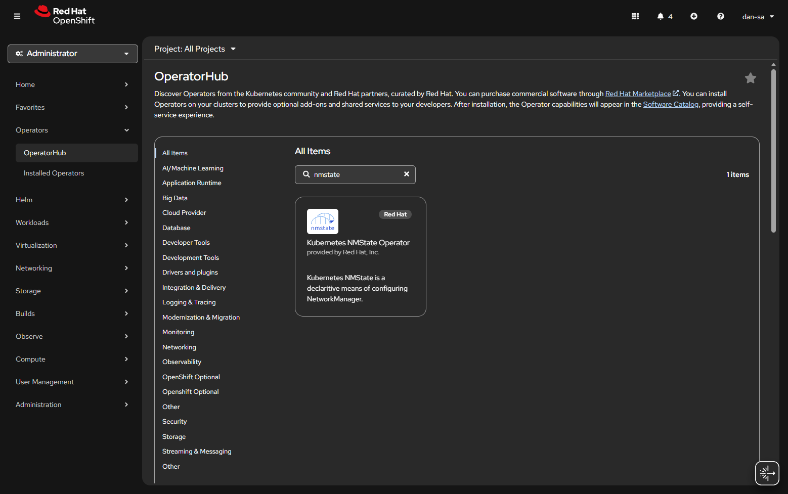
  • Click Operators -> OperatorHub.
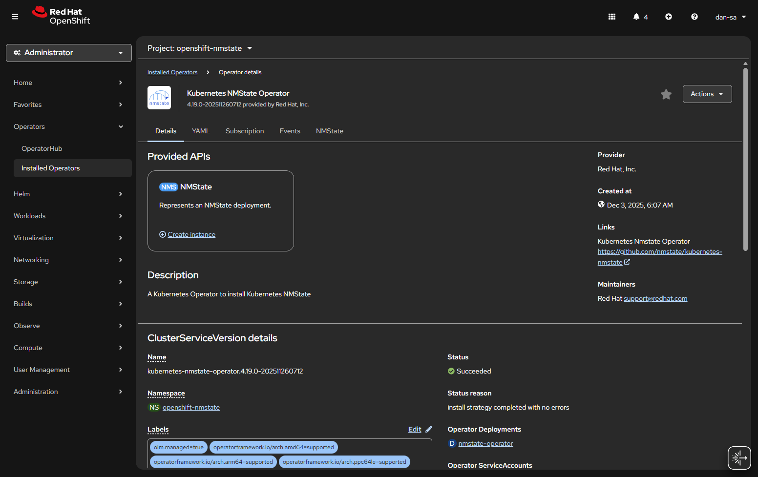
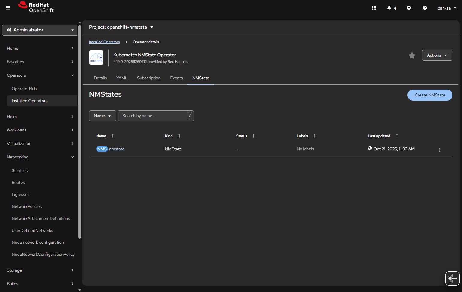
  • Once installed, you will need to create an “instance” of NMState for it to activate.
  • Then there will be new options under the Networking section on the left. We want NodeNetworkConfigurationPolicy. Here we create policies of how networking should be configured per host. This is like Group Policy or Puppet configurations.
  • At the NodeNetworkConfigurationPolicy screen, click “Create” -> “With YAML”.
  • We need to create a new sub-interface off of our eno1 main interface for our new vlan, then we need to create a Linux Bridge off that interface for our VMs to attach to.
apiVersion: nmstate.io/v1
kind: NodeNetworkConfigurationPolicy
metadata:
  name: vlan19-with-bridge           <-- Change This
spec:
  desiredState:
    interfaces:
      - name: eno1.19             <-- Change This
        type: vlan
        state: up
        ipv4:
          enabled: false
        vlan:
          base-iface: eno1
          id: 19                     <-- Change This
      - name: br19                   <-- Change This
        type: linux-bridge
        state: up
        ipv4:
          enabled: false
        bridge:
          options:
            stp:
              enabled: false
          port:
            - name: eno1.19       <-- Change This
              vlan: {}
  • Important things here:
    • Change the 19s to whichever VLAN ID you want to use.
    • “ipv4: enabled: false” says we want an interface here, but we are not giving it host level IP networking on our OpenShift node.
    • Remove the <– Change This comments
    • You MUST leave the “vlan: {}” at the end or it will not work, adding this tells it to leave vlan data how it is because we are processing via the kernel via sub interfaces.

Now we have this configuration, with a secondary interface off of our NIC, and an internal Linux Bridge for the VMs.

The great thing about doing this configuration via NMState, it applies to all your nodes unless you put a filter in, and you get a centralized status about if each node could deploy the config.

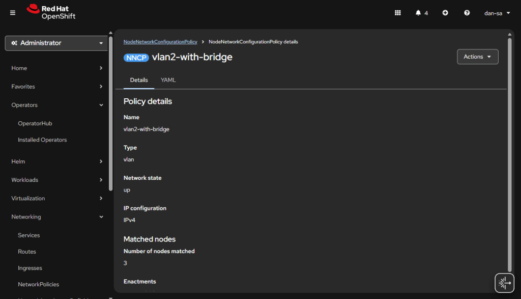
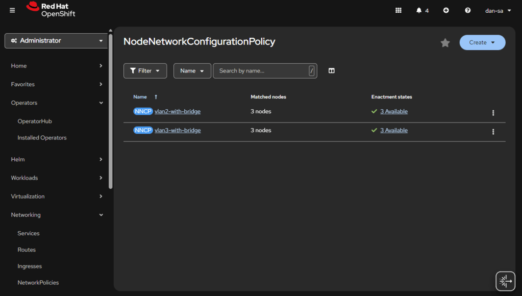
Here is an example from my Homelab, with slightly different VLAN IDs than we have been discussing. You can see all three nodes have successfully taken the configuration.

OpenShift VM Network Configuration

Kubernetes and OpenShift use Network Attachment Definitions (NADs) to configure rules of how pods can connect to host level networking or to the CNI. We have created the VLANs and Bridges we need on our host system, now we need to create Network Attachment Definitions to allow our VMs or other pods to attach to the Bridges.

  • Go to “Networking” -> “NetworkAttachmentDefinitions”.
  • Click “Create NetworkAttachmentDefinition”
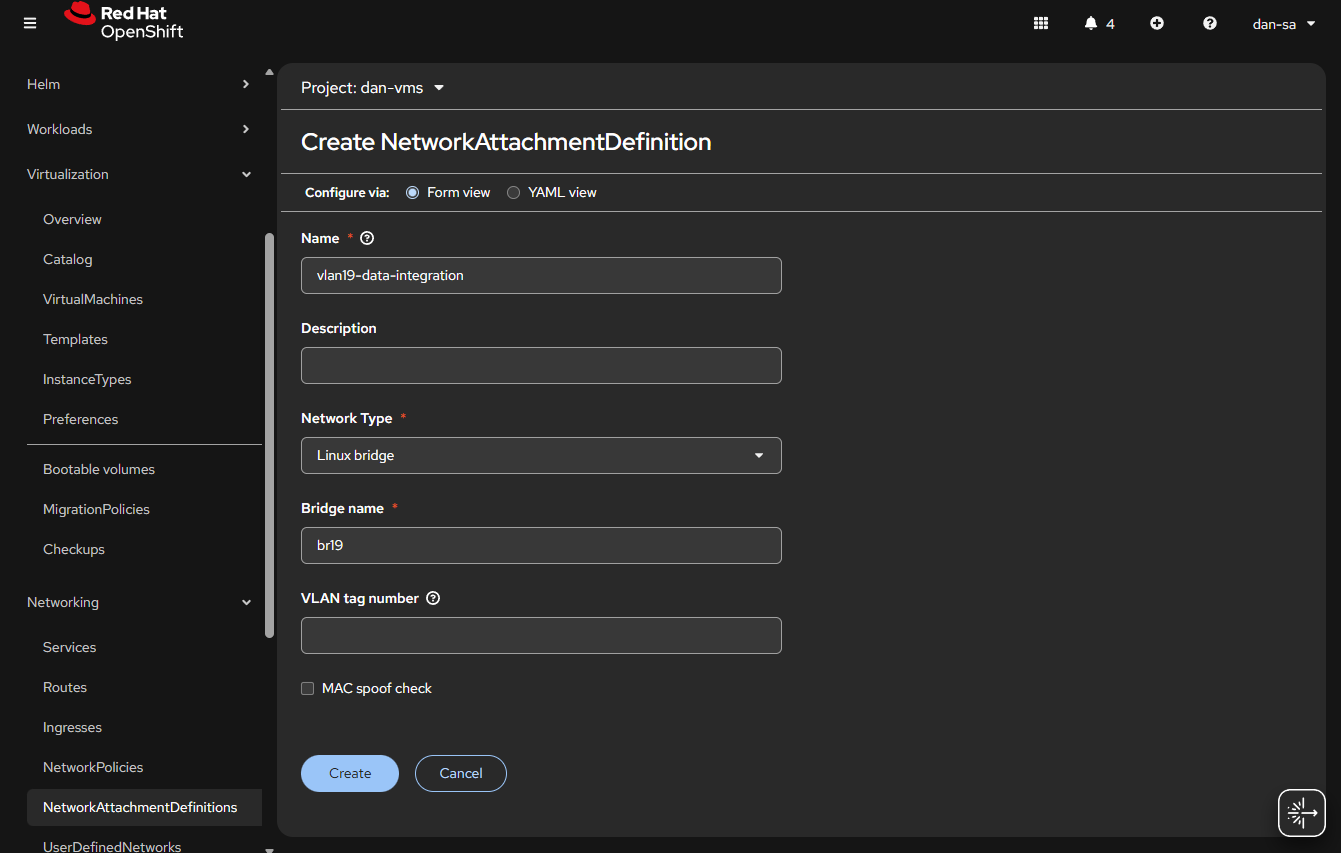
  • This is easily done, and can be done via the interface or via YAML, first we will do via the UI then YAML.
  • Before entering the name, make sure you are in the Project / Namespace you want to be in, NADs are Project / Namespace locked. This is nice because you can have different projects for different groups to have VMs and limit which networks they can go to.
  • Name: This is what the VM Operator will select, make it easy to understand, I do “vlan#-purpose“, example: “vlan2-workstations”.
  • Network Type: Linux Bridge.
  • Bridge Name: what was set above, in that example “br19“, no quotes.
  • VLAN tag number: Leave this blank, we are processing VLAN data at the kernel level not overlay.
  • MAC spoof check: Do you want the MAC addresses checked on the line. This is a feature which allows the network admin to pin certain MAC addresses and only send traffic out to those allowed. I usually turn this off.
  • Click “Create

The alternative way to do a NAD is via YAML, here is an example block:

apiVersion: k8s.cni.cncf.io/v1
kind: NetworkAttachmentDefinition
metadata:
  name: vlan19-data-integration
  namespace: default
spec:
  config: |-
    {
        "cniVersion": "0.3.1",
        "name": "vlan19-data-integration",
        "type": "bridge",
        "bridge": "br19",
        "ipam": {},
        "macspoofchk": false,
        "preserveDefaultVlan": false
    }

You can verify the NAD was created successfully by checking the NetworkAttachmentDefinitions list. Your networking is ready now. Next post, we will discuss getting storage setup.

Additional NodeNetworkConfigurationPolicy YAMLs

NIC Bonding / Teaming

Use mode 4 (802.3ad/LACP) if your switch supports link aggregation; otherwise mode 1 (active-backup) is the safest fallback.

apiVersion: nmstate.io/v1
kind: NodeNetworkConfigurationPolicy
metadata:
  name: bond0-config
spec:
  desiredState:
    interfaces:
      - name: bond0
        type: bond
        state: up
        ipv4:
          enabled: false
        link-aggregation:
          # mode=1 active-backup
          # mode=2 balance-xor
          # mode=4 802.3ad
          # mode=5 balance-tlb
          # mode=6 balance-alb
          mode: 802.3ad
          options:
            miimon: '140'
          port:
            - eno1
            - eno2

Useful Links

https://github.com/k8snetworkplumbingwg/multus-cni/blob/master/docs/how-to-use.md

https://medium.com/@tcij1013/how-to-configure-bonded-vlan-interfaces-in-openshift-4-18-0bcc22f71200

Manually Flashing a AsRock BIOS

At the start of 2022 I went about building a new desktop. The system came out well in the end, and I am still using it although it has always had one issue that I mentioned back then… When the system tries to reboot it shuts down Windows, then the fans spin up, and it never resets the CPU. I always assumed this was due to the fact: mistakes were made and when I needed a BIOS update to support the AMD Ryzen 5800X on that motherboard, I flashed the X570 Pro4, NOT X570M Pro4 BIOS. I decided the time had come to fix this and flash the board back to the proper BIOS.

Note: I will use BIOS and UEFI interchangeably here, I know they are technically different.

AsRock gives out the BIOS updates, and you are supposed to load them on a USB drive and select the “Instant Flash” utility in the UEFI menu. The issue is the system thinks it’s a X570 Pro4 (not M), and refuses to flash to the M variant. I saw some people on the internet mention you can use the “AMIBIOS and Aptio AMI Firmware Update Utility” utility to force a BIOS flash on the system and get around this. I did that, and then… the system never booted again… I don’t know what went wrong, or if the utility flashed everything correctly, but I couldn’t get the system to boot.

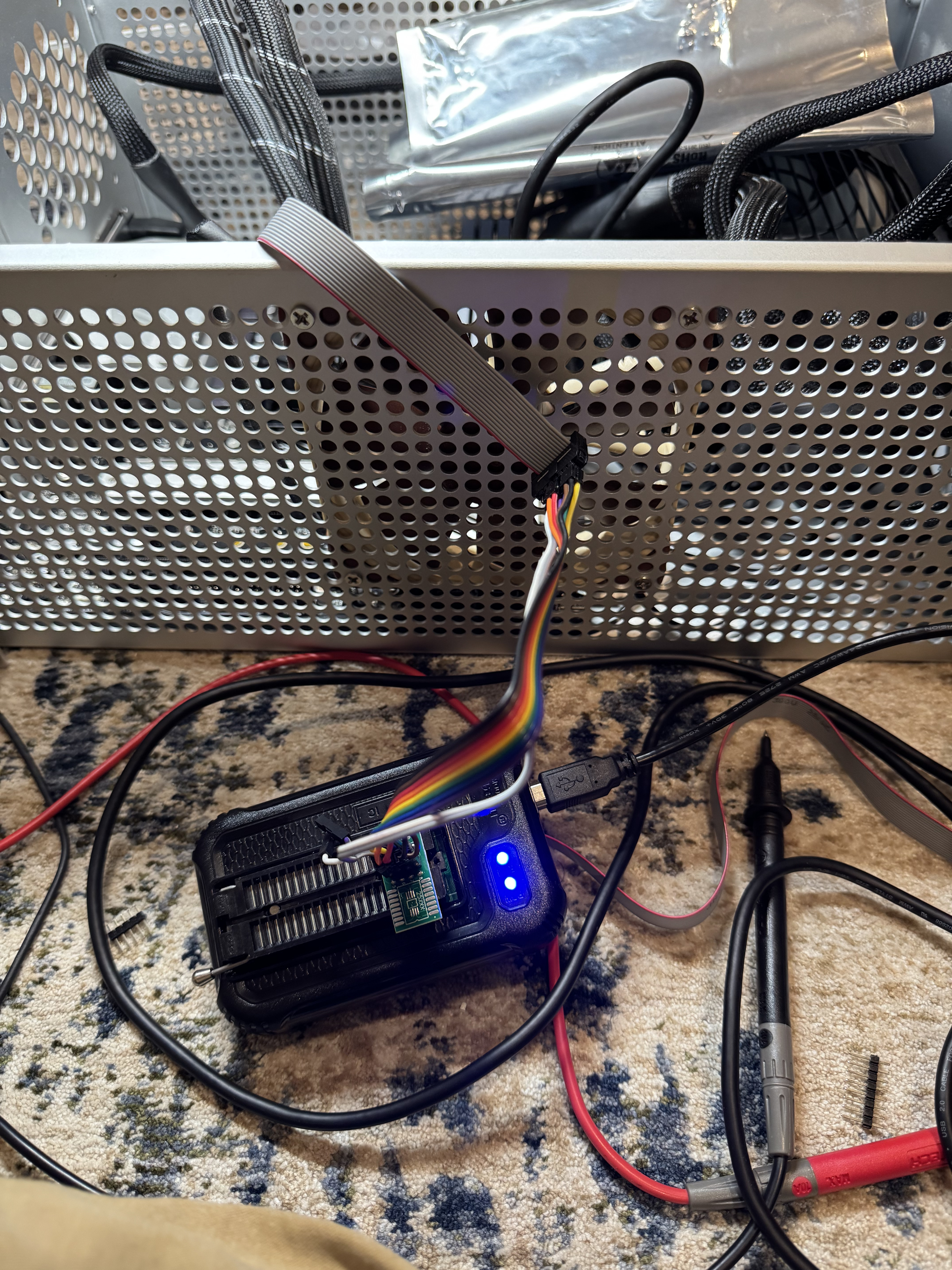
This led me to another rabbit hole, flashing your bios with an EEPROM writer. There are several to choose from, and of course I got both. The CH341A, and T48 TL866-3G programmers. I tried for a while to get the CH341A to work, and it may have in the end, but I had a better time with the TL866 software of XgPro.

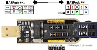
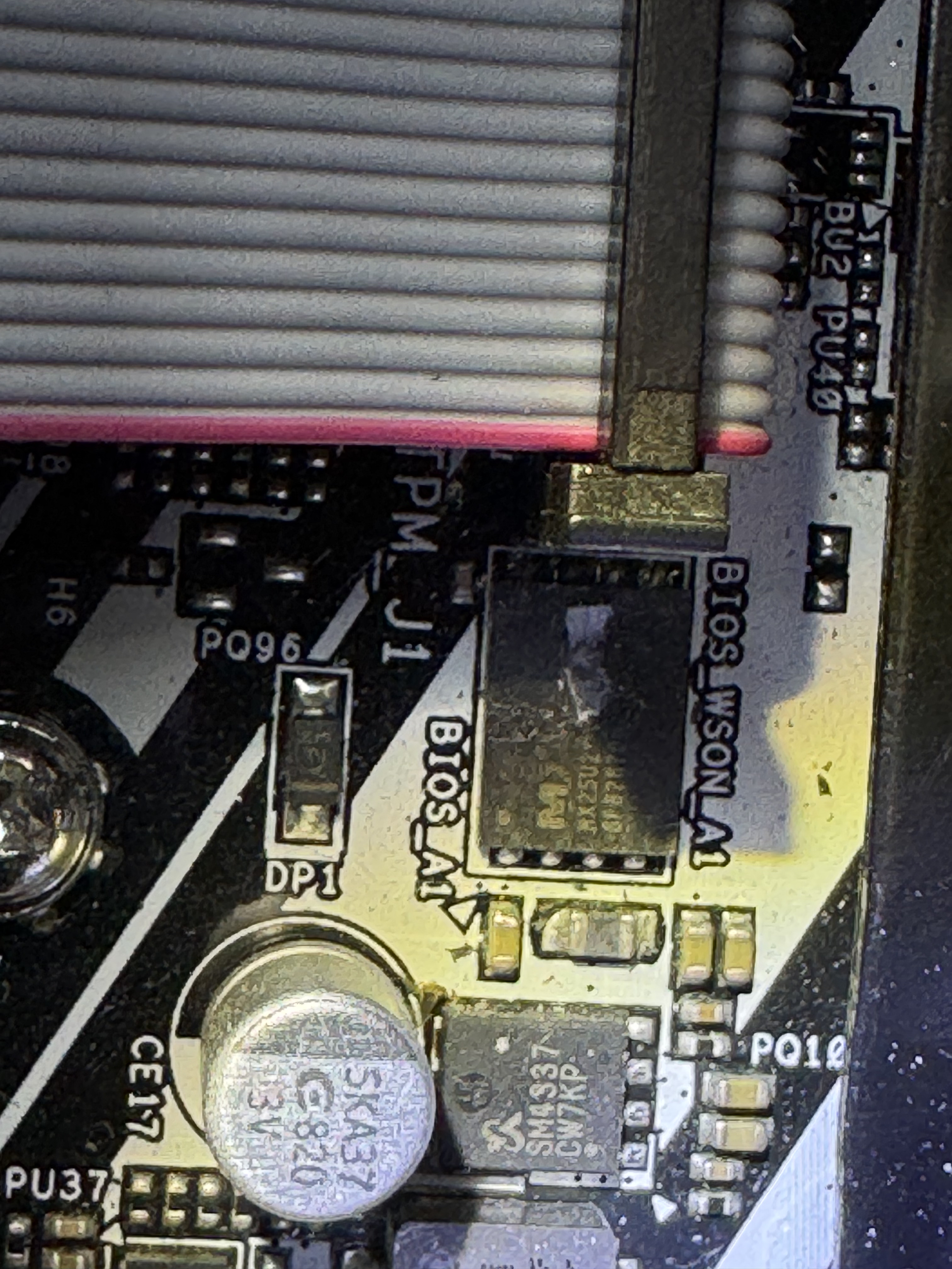
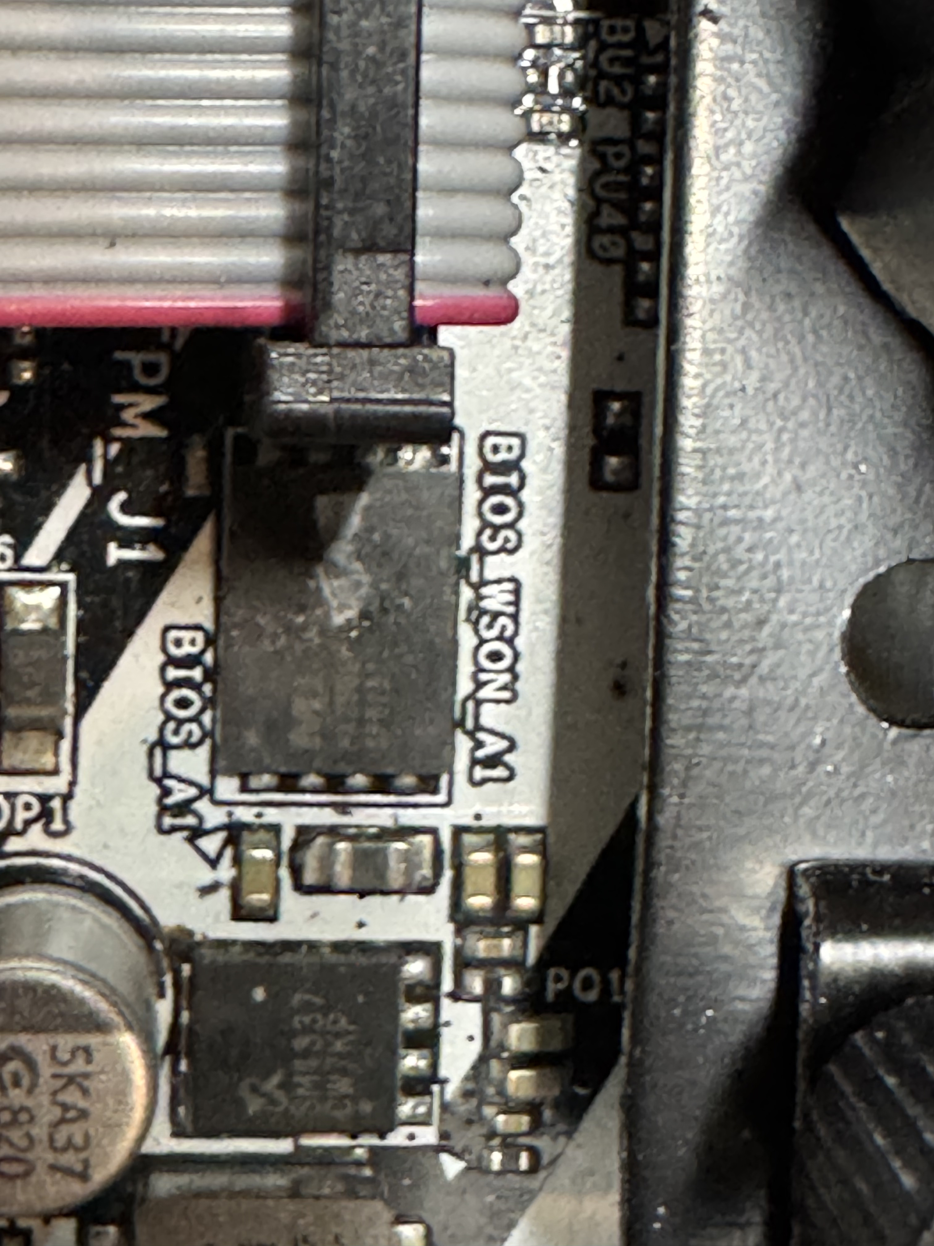
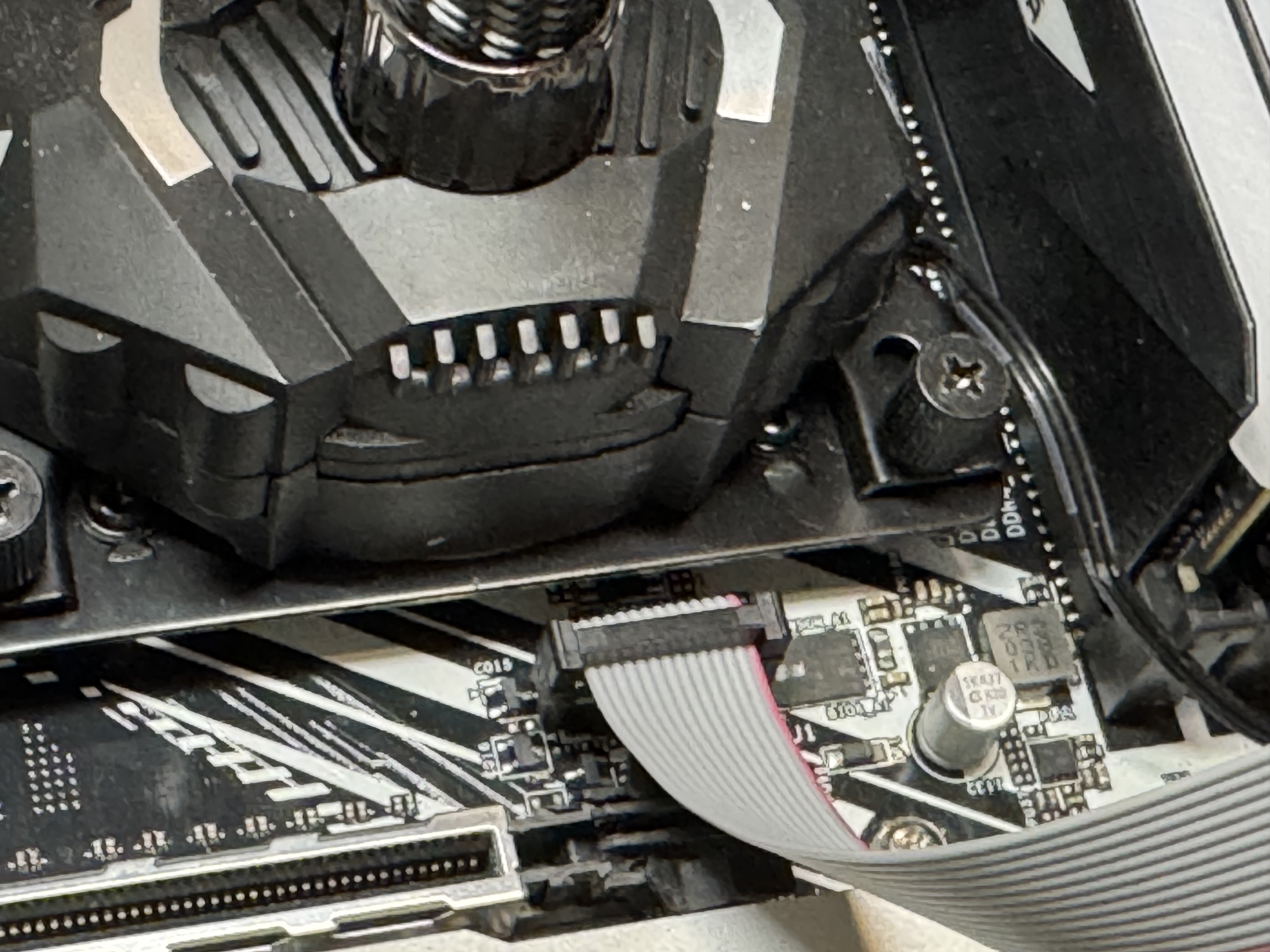
I unplugged everything and took out the BIOS battery. At first, I tried to use some of the tools that came with the flashers to grab the chip on the motherboard. Here was the first hurtle, the chip was a surface mount part that made it very difficult to connect to and every time I tried to read the chip I got an error. Then I found this post, https://www.reddit.com/r/ASRock/comments/1cz1bcz/guide_asrock_spi_tpm_j1_bios_ph_pinout_for_ch341a/, which mentioned the SPI_TPM_J1 header on the motherboard actually hooked directly to all those pins and could be used to flash the chip much easier.

Pinout from Reddit

This diagram was the key to getting it working, which pins went to where on the motherboard.

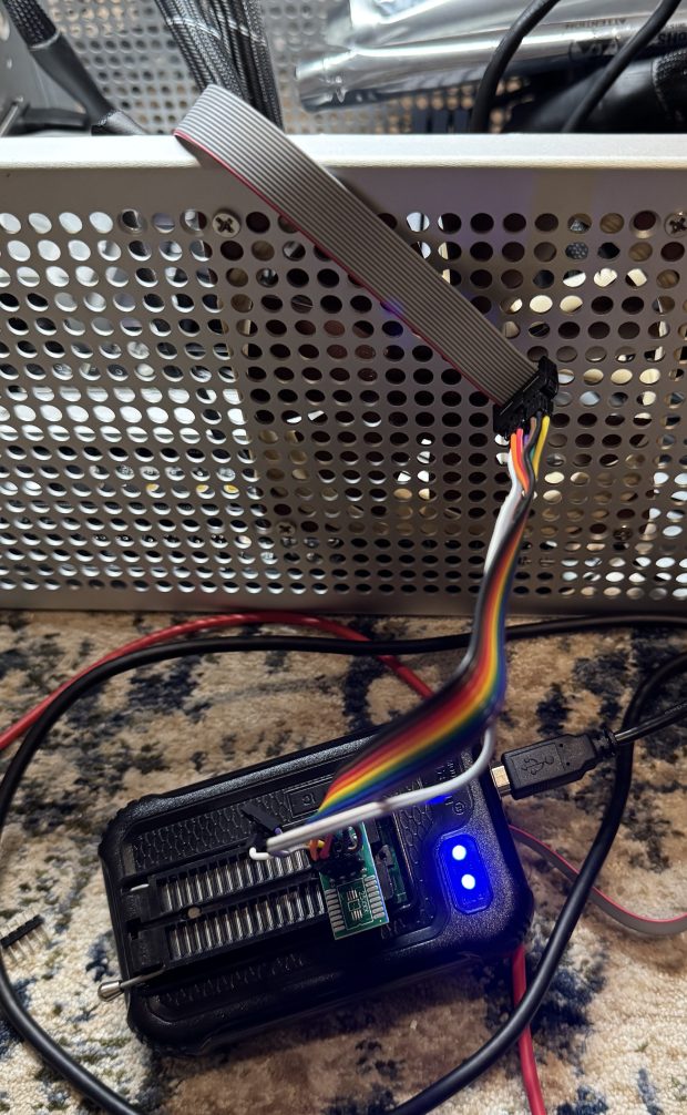
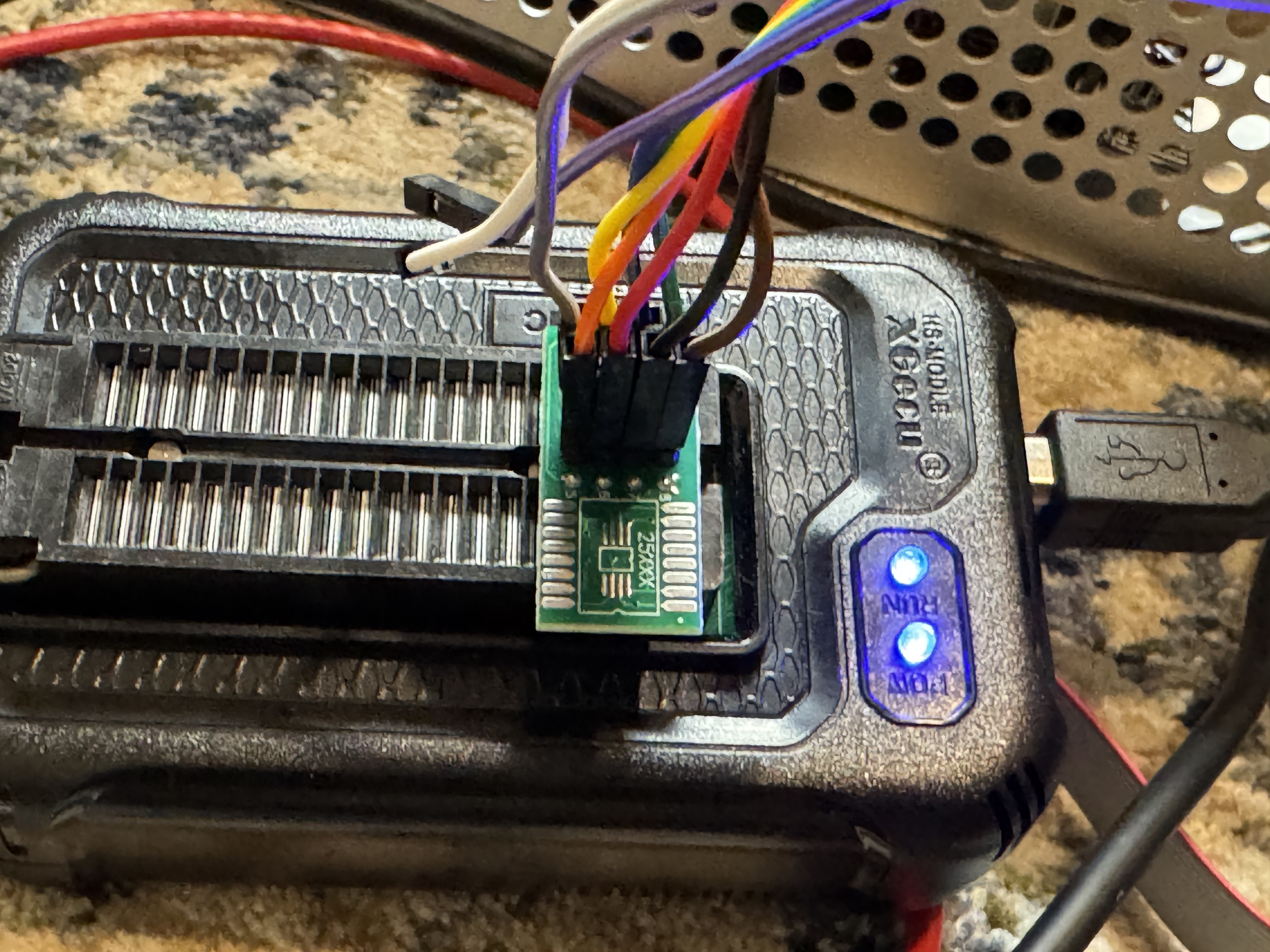
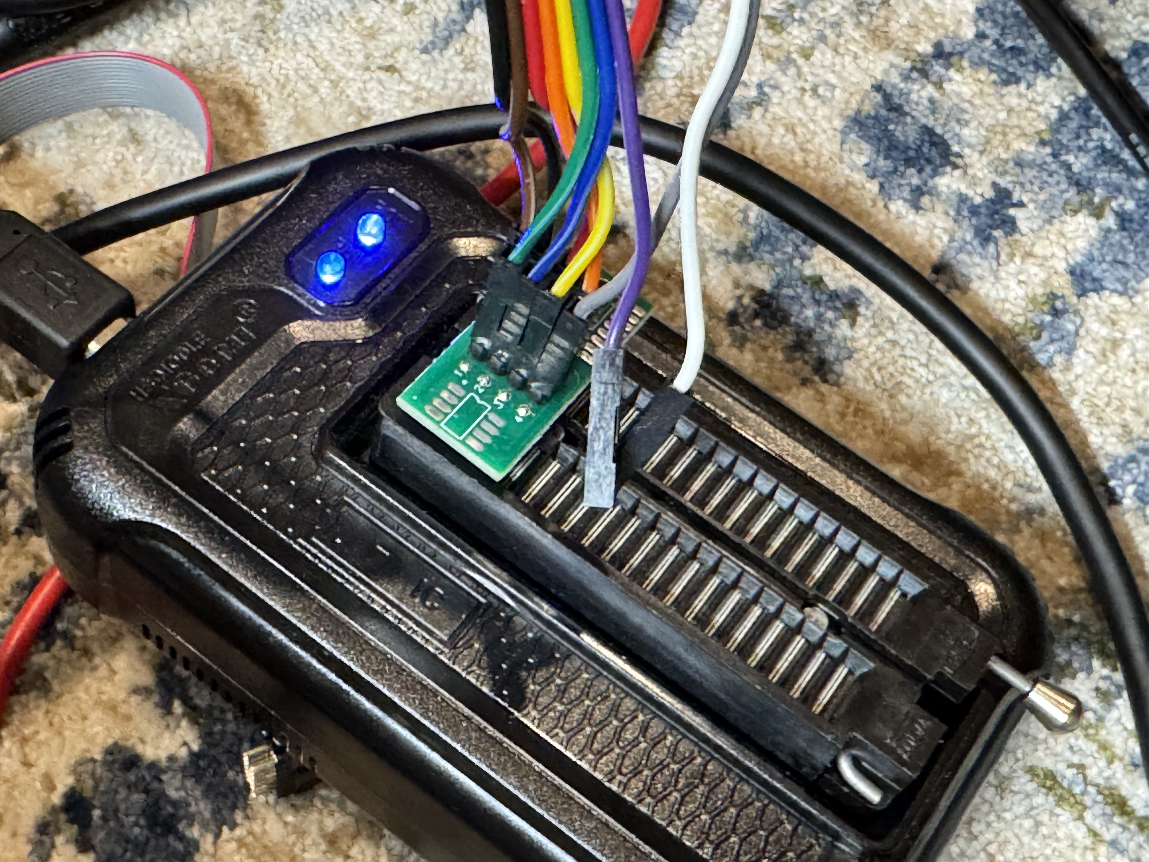
Connecting to the pins proved to be a bit difficult because of how small they were. Turns out they are 2mm pitch instead of 2.54mm (more standard), so I had to order https://www.amazon.com/dp/B07FKLKM7L as one of the commenters suggested to be able to connect easily to the pins. Then I did some janky stuff with jumper wires to get it into the TL866 programmer.

The programmer also uses Windows-only software, and I was on my Linux laptop. I installed a Windows 11 VM and forwarded the USB device to use the software. The Reddit post mentioned that they had a similar motherboard and needing to use the 1.8V adapter for their Winbond W25Q256JW BIOS chip. I assumed the same but when I went to read the bad BIOS back, I was given “ID Check Failed 0xC2 25 39”. Which turns out to be a 3.3V Macronix MX25L256, with Claude assuming it’s a MX25L25673G. I pulled out the 1.8V adapter and hooked right to the chip. I still failed to get an ID with the built in tool, and when I forced the chip type, I was told one pin wasn’t connected right. I adjusted the pin and hit READ again and got a hit, the ID didn’t match the software’s record for that chip type. I ended up disabling ID Check and then doing a read. AND I GOT DATA! This showed my wiring was good enough.

From there I went and got a new BIOS from AsRocks site. Seeing the BIOS file was exactly 32MB, and the BIOS was 256 megabits = 32MB, I felt confident that I could write this whole image and it didn’t have a header or something that would break directly writing this image to the chip.

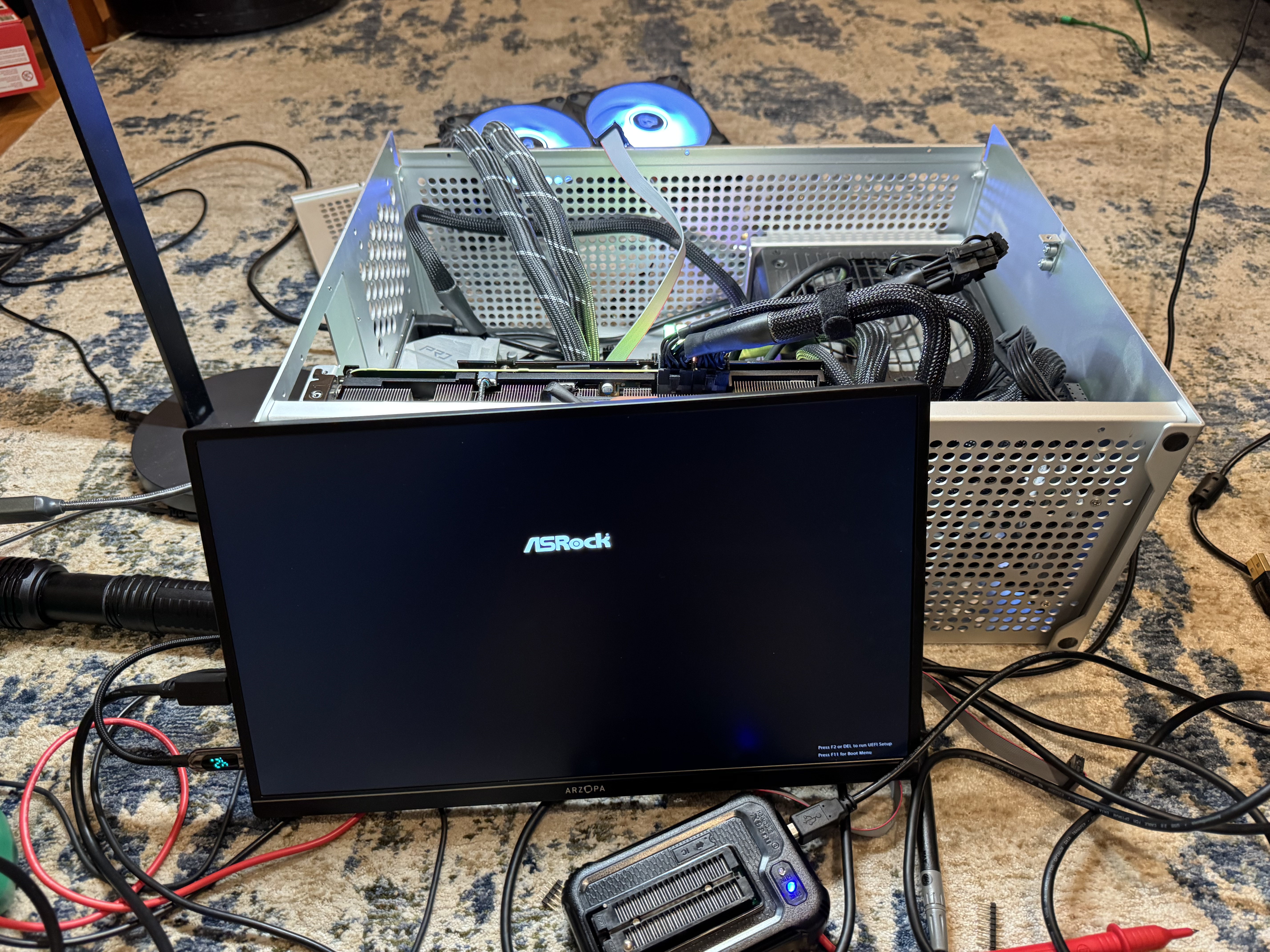
I hit program and crossed my fingers. After a minute of erasing, then a minute of programming and verifying it said it was done. I unplugged my laptop, and plugged power back in. The system came on when I hit power, but again no POST. Then I waited a minute, and it powered off, this time, when I powered it back on the system came to life with the AsRock UEFI screen! I had to re-enter UEFI settings but we are back!

The last and final irony… on the correct BIOS, up to date, the system still fails to restart…

Mellanox Driver Ignoring Vlans

Recently I have spent more hours than I want to talk about fixing a server that had a Mellanox ConnectX6-lx card, where I could not get OpenShift to get traffic to VMs. I would create Linux bridges just like I normally do, and traffic was working to the main interface, except all the traffic was being sent to the primary Linux interface, and not the sub interfaces on specific VLANs that I needed it to. Other systems, with other network cards were not having this issue. After some trial and error, finding specific kernel messages, and solving it, I wanted to make a quick post in case anyone runs into this.

All of this analysis and guide will assume a trunk port to an interface on Linux (or a bonded interface). If you have an interface in Linux on the native VLAN, and that is a standard interface (example eno1). Then you add a sub interface for tagged traffic, eno1.10, the Mellanox mlx5 driver will – in hardware – ignore your VLAN tag and just send traffic to the main interface.

The smoking gun that helped me find the answer was looking at the dmesg kernel logs; search dmesg for “mlx5”: dmesg | grep mlx5, you may see the following:

mlx5_core 0000:0b:00.1: mlx5e_fs_set_rx_mode_work:843:(pid 156): S-tagged traffic will be dropped while C-tag vlan stripping is enabled

(https://github.com/oracle/linux-uek/issues/20) This line let me find discussion online about this kernel bug, and people discussing ways to resolve.

The Mellanox card thinks there are double tagged VLAN frames and will drop tags on data coming in. The Mellanox card does this in hardware. You can check the settings for 802.1Q kernel module being loaded, and VLAN filtering is disabled in the kernel, but this won’t matter. If you change settings like ethtool -K <interface> rx-vlan-offload off it will say the setting is off, that is correct because the Mellanox firmware is doing the filtering, not the Linux kernel. When you tcpdump the interface, you will see weird results, because you are capturing traffic AFTER the firmware has dropped the header.

The only way I found to fix it is to move all the IPed interfaces off the main interface. Do not use the native VLAN to carry traffic. (Probably a good idea anyway, but this system got into this state by a port being migrated FROM access TO trunk and originally trying to do this with minimal interruption.)

Once you move the IPed interface under its own sub interface and reboot, data will start flowing to your VMs. The kernel module will reload and not attempt to remove the “outer” VLAN tag from the “double tagged” packets. This was a harder issue to solve because of the fact it only triggers on load, which means you have to reboot to find the correct fix. I saw a handful of other people mention this issue in bug reports, and that set me on the correct track.

Another part of the challenge was the system I was using was a blade server with an internal “dumb switch”, and I was never sure what that switch was doing with the tagged packets. In the end, not much, but added a complexity to the problem.

Update from the future: I have written more about networking in OpenShift and this issue in a new post Step-By-Step Setting Up Networking for Virtualization on OpenShift 4.19 for a Homelab | BuildingTents

Homelab Dial-Up Networking for Retro Computing

I started mentioning about my LAN Before Time project before. The idea is to have a rack of the most diverse CPU, OS, and Networking technologies I can find. Each computer and piece of equipment bringing something new and unique to the collection. One part of this collection was the network. Coming from a networking background, I also wanted to have the most diverse set of networking technologies that I could. To do this I would need to find a core router that could talk all the different protocols I wanted. Having worked at Cisco in the past, I knew they had gear that went back in time, and could add in some additional fun like AppleTalk. That is where I started my search.

Why the Cisco 3825

I knew I needed a Router and not a switch, because we would be going between several protocols. I could time box the router a bit because I wanted to support AppleTalk and IPX. Support from these no longer exists, and thus would give a cutoff for devices I could get.

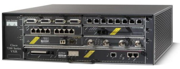
Years ago, I was the Cisco 7200 VXR guy at work. They were great routers, that could go up to gigabit and go in and out of a ton of different connections, including some voice ones. The issue was they could do lines like T1, but they couldn’t host an analog modem, and that was one thing I very much wanted.

Now we are getting down to a select group of Cisco devices. I started making a table of the pros and cons of each. I also was hoping for something slightly newer to have 1gb/s links available, and hoping that it wouldn’t use a 1000 watts at idle.

This is a table I made of all the different options for routers and the features they supported:

Model (U) Small Bays Large Bays Token Ring IPX / AppletalkDial-Up Base Speed EOL Date Flash
2513 (1) 10mb Before time Internal?
3640 (2)Y / Y100mb 2008-12-31 PCMCIA
3725 (2)Y / Y100mb 2012-03-31 CF
3745 (3)Y / Y100mb 2012-03-31 CF
3825 (2)Y / Y1000mb 2016-11-1 CF + USB 
3845 (3)Y / Y1000mb 2016-11-1 CF + USB 
3945 (3)N / N1000mb 2022-12-31  
7206XVR (3)Y / Y1000mb 2017-02-28? CF/PCMICA 

The Cisco 1800/2800/3800 line all came out around the same time, they were considered the G1 generation routers. Things before them were legacy, and the systems after them like the 3945 were the G2 devices. G2 was a step to get rid of legacy, this means dropping AppleTalk, IPX and some of the things I was interested in. By this point I had realistically narrowed down to a Cisco 3725 or 3825. The 3825 had gigabit on the main controller, allowing my to get a little closer to modern systems; that put me over the edge for it. I also was not interested in its giant cousin, the 3845; the 3825 had enough bays and should be quiet enough for me to run routinely.

Cisco 3825 Back

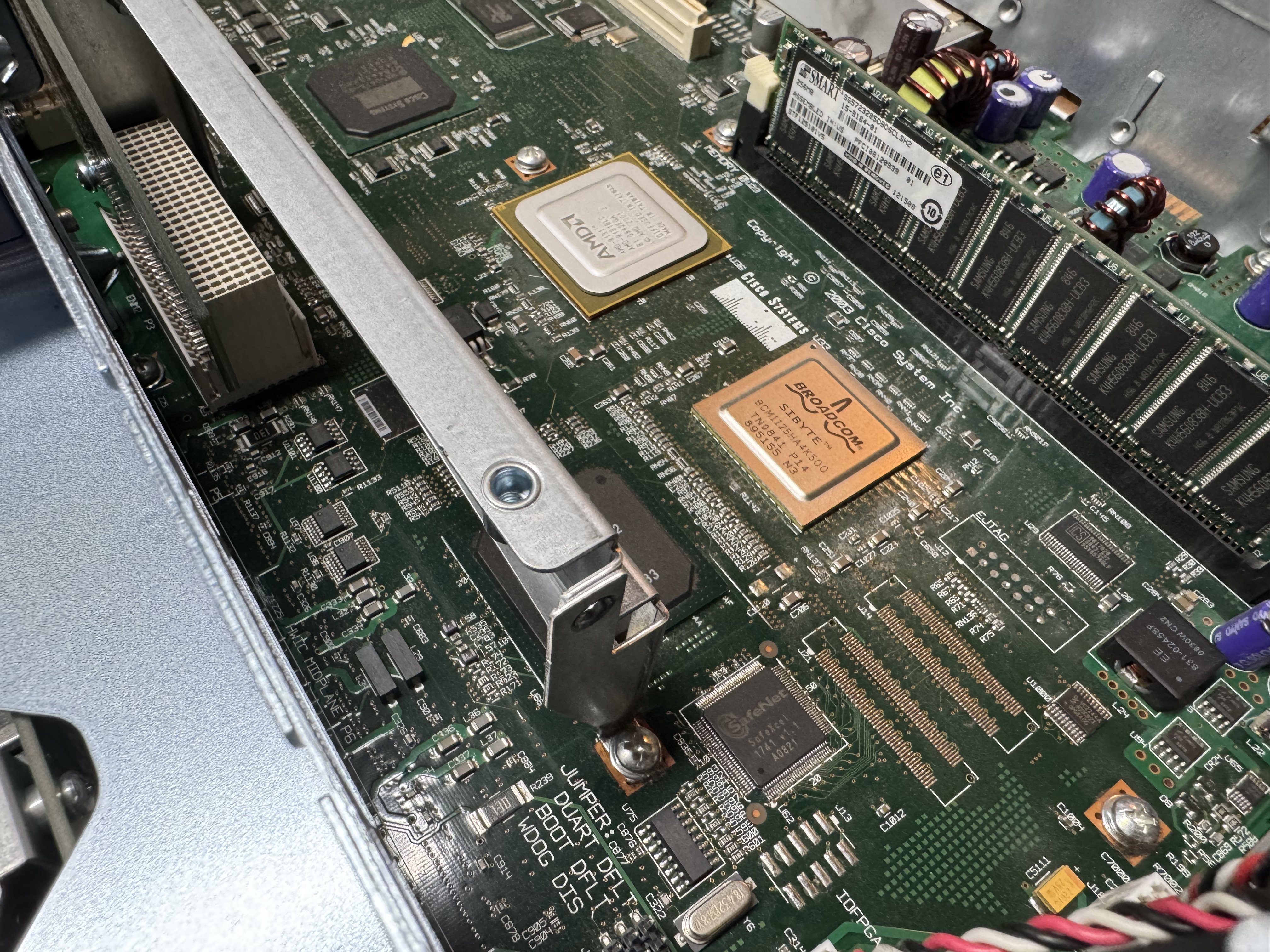
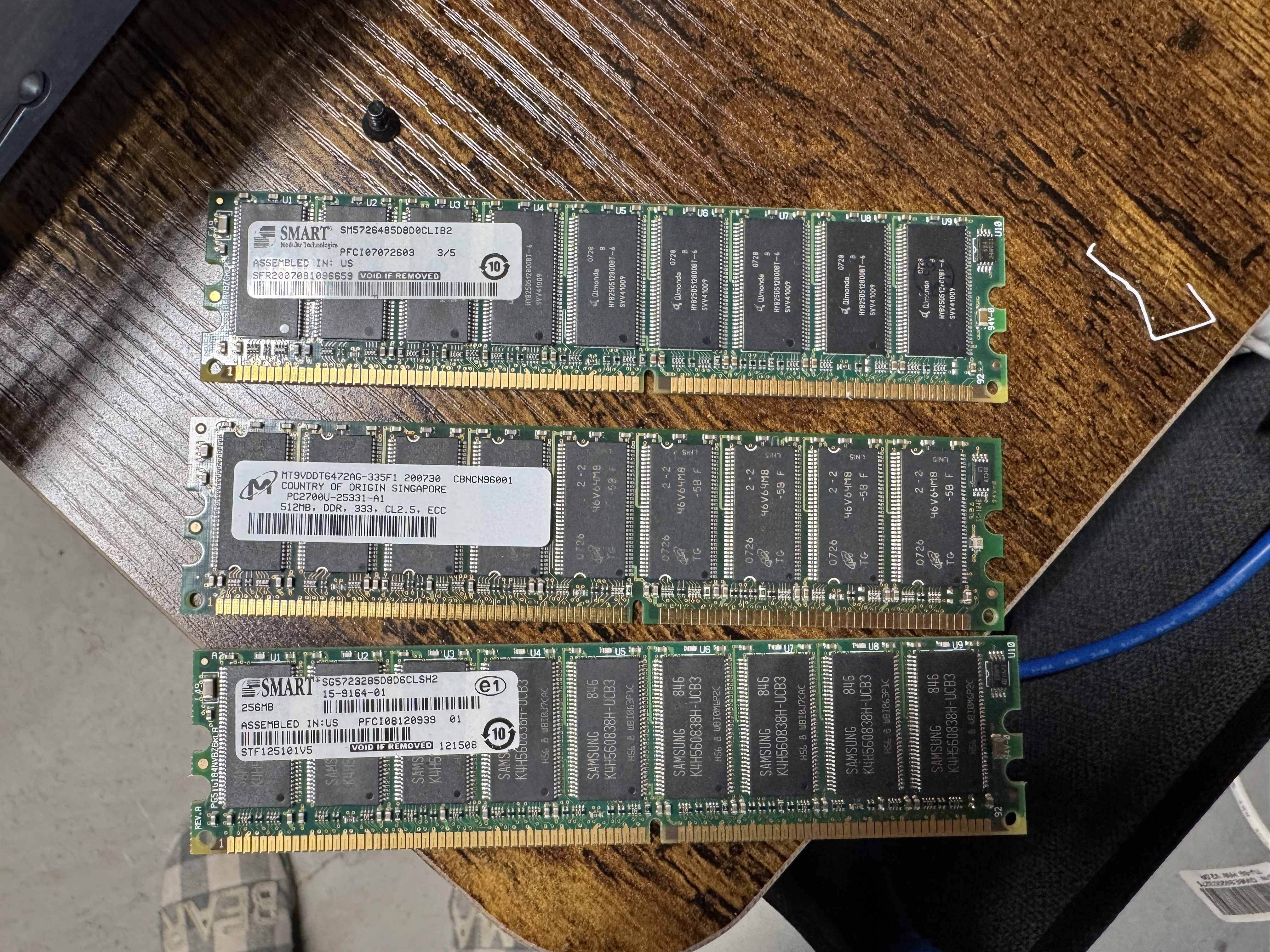
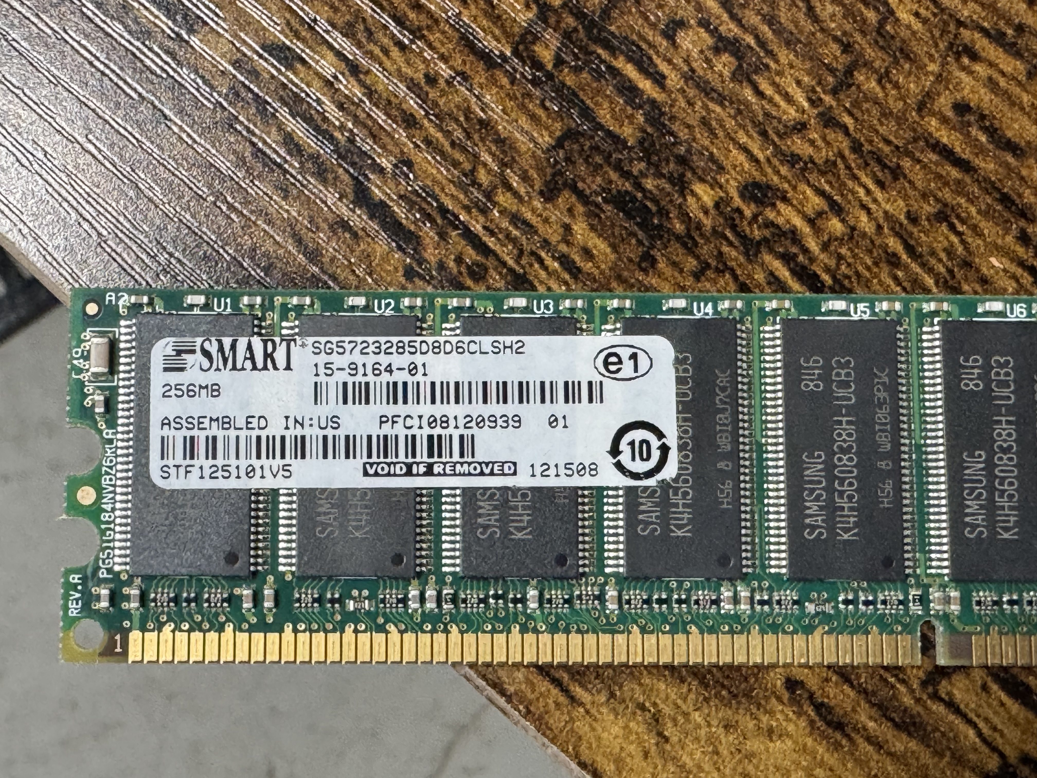
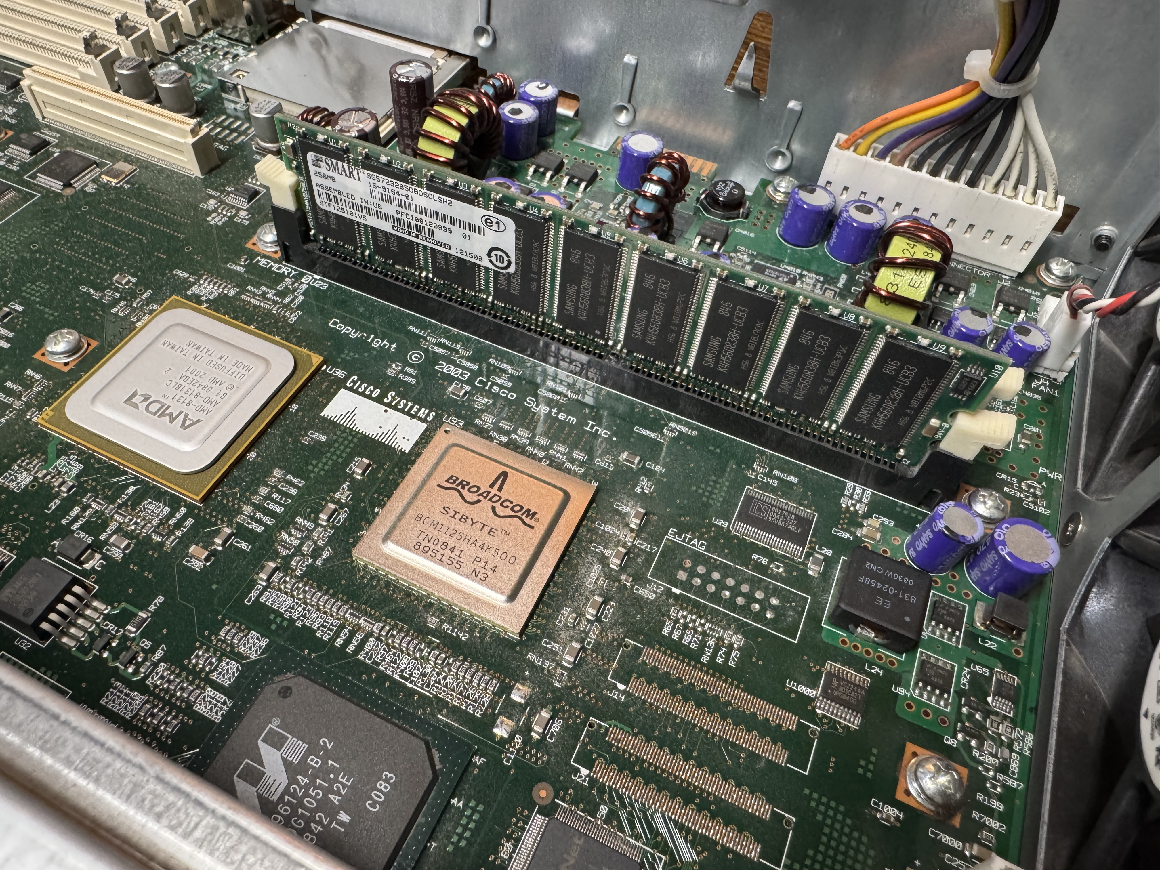
In searching for the voice features I wanted, I found I would need the Advanced Services image loaded, and that required a minimum of 512MB of memory. I ordered a system with Advanced Services and 1GB of memory, the max! When it came it had 256MB! I emailed the seller and he mailed me the proper 1GB of RAM. Once I installed it, the system would boot loop, I found one of the 2 sticks was bad. I ended up putting in one of the 512MB sticks he sent, and the 256MB one it came with for a total of 768MB of RAM.

Upgrading the Cisco 3825

Once I had the device on order, I started learning about the world of voice. I had not done much with voice before, there was a lot to learn. First, I needed to know which cards I would need. The 3825 can run older WIC cards, and the newer high speed HWIC cards. I needed analog modems, and to host those, I needed FX-S/FX-O cards. In learning about them: FX-S Foreign Exchange Station, FX-O Office. The office is for a branch office dialing OUT. You usually want FX-S because it provides a dial tone to dial into. S is to get a dial tone and you can call INTO. O is it receives a dial tone.

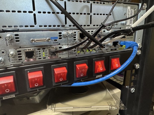
I got 4 FX-S Ports. One port is used to dial into, another to route the call out. I need more ports than you would think because of this. I got a CISCO VIC3-4FXS/DID, this gives 4 ports in/out. 2 CISCO WIC-1AM-V2, giving 2 modems I can dial into. There are cards that are 2 modems in one card, but they are rare and expensive. (I would get one later)

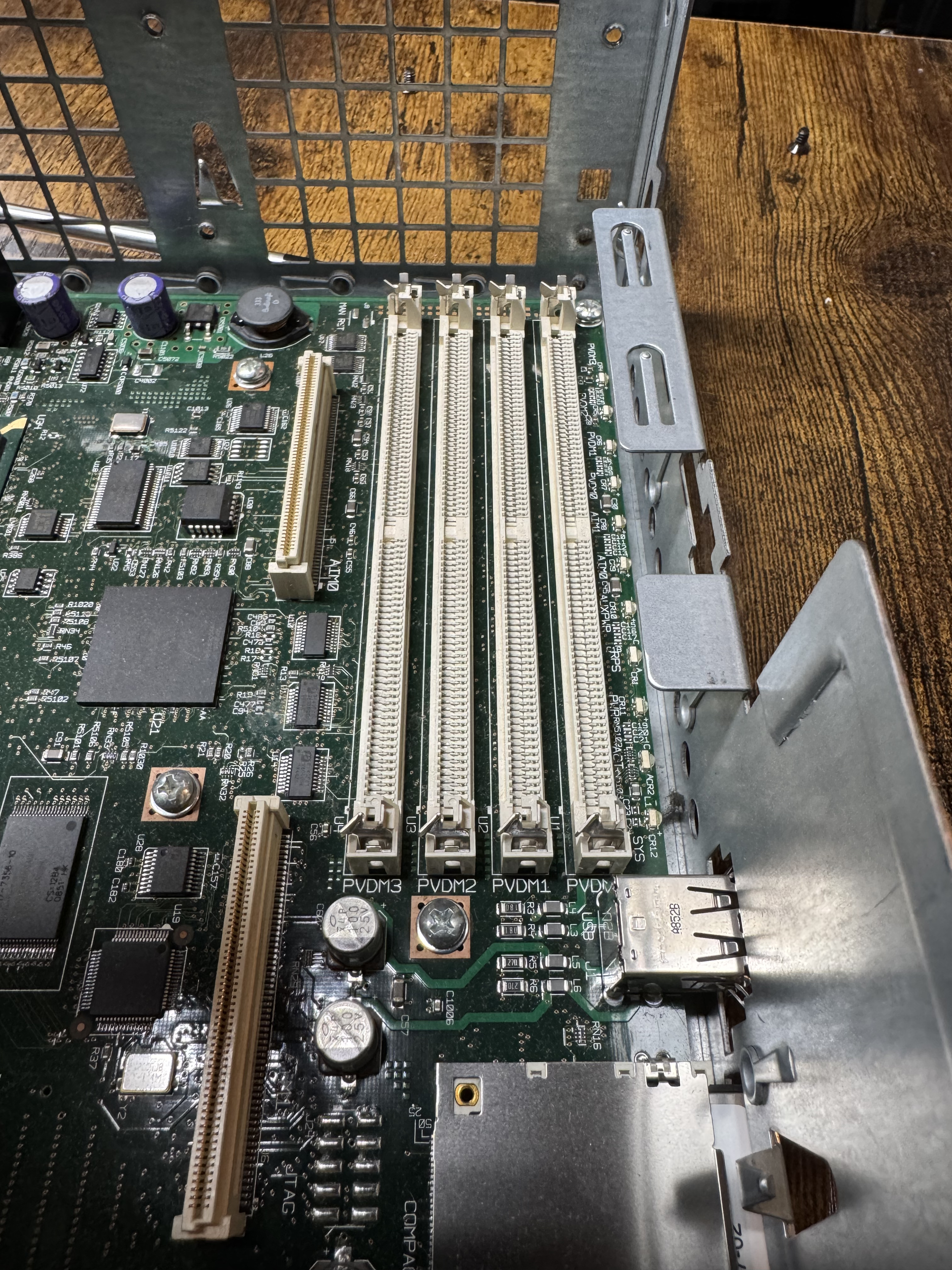
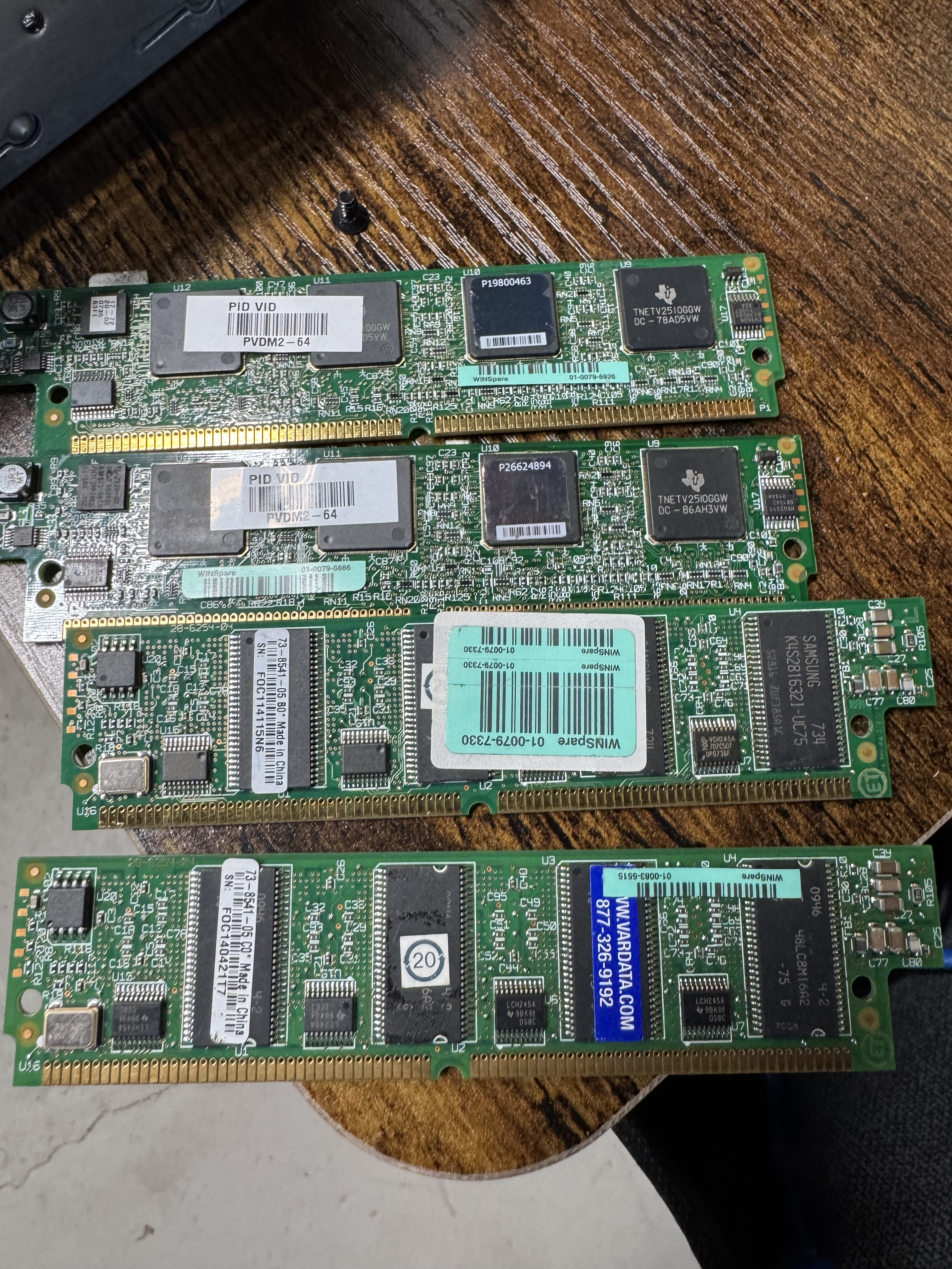
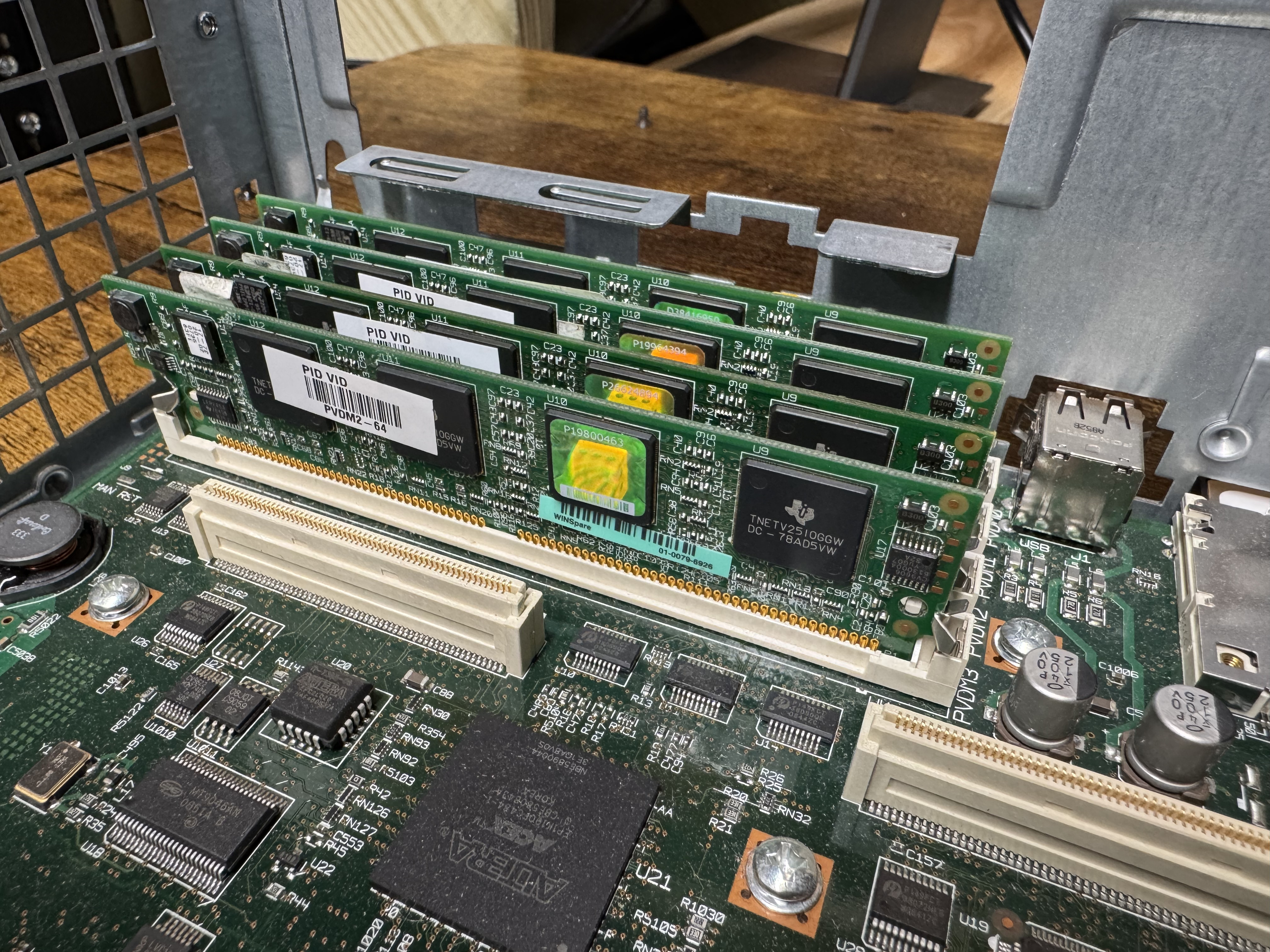
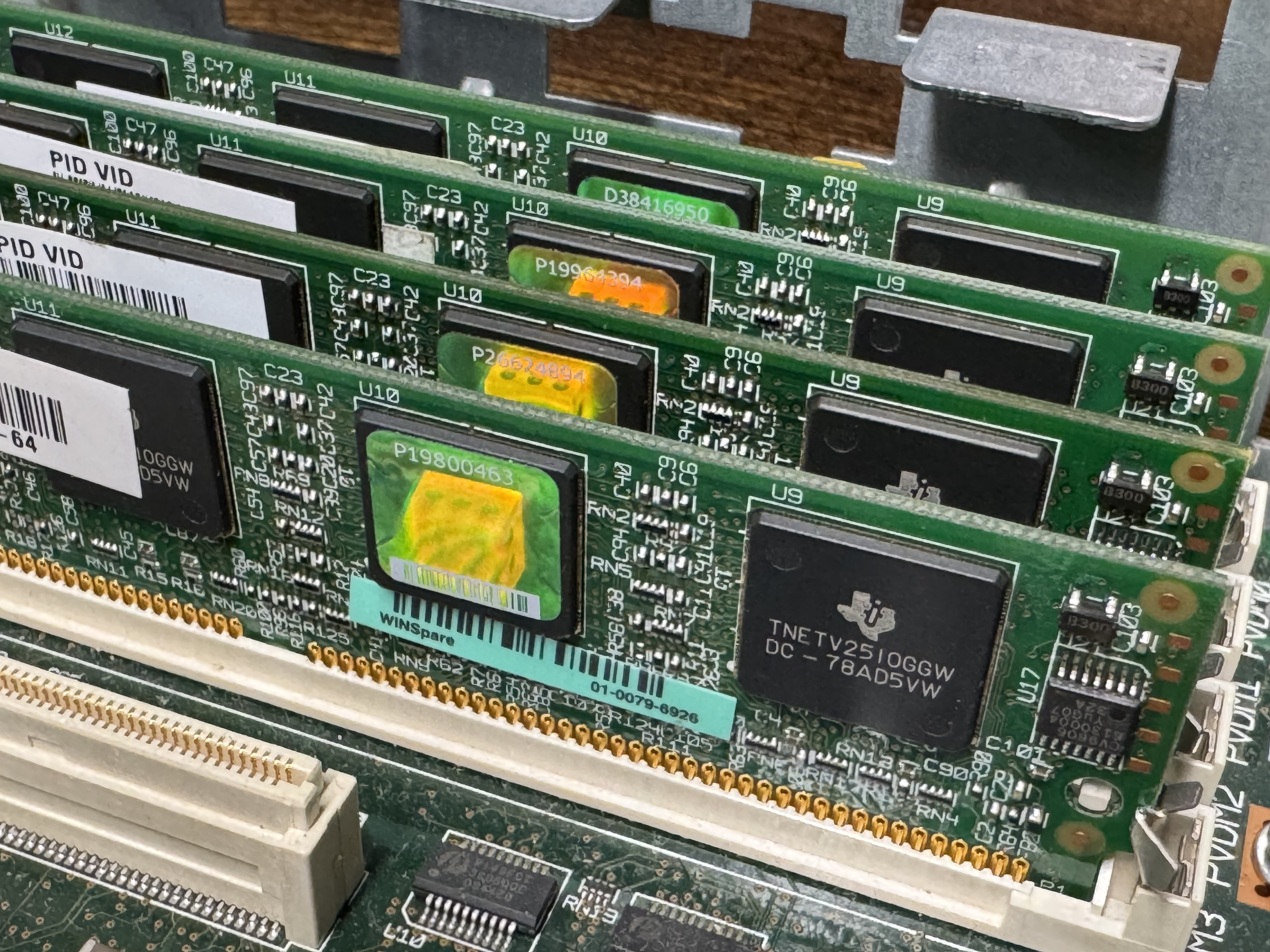
The system now has 768MB of memory, but I would also need PVDMs; Packet Voice Digital Signal Processor (DSP) Module (PVDM2). I had not worked with these before. They are ASICs that come process voice channels. They come in different numbers of channels, PVDM2-8, PVDM2-16, PVDM2-32, PVDM2-48, PVDM2-64. They were cheap, obviously I got 4 PVDM2-64 to go to 256 voice channels for $20 USD. The math is odd here, there are different complexity channels and some knock you down to 1/2 or less of the listed available channels. A “high complexity codec” can make an 8-channel card only handle 4 or less channels. Like I said, these were cheap, so I got 4 256-Channel cards. The cards go into slots that look like DIMMs.

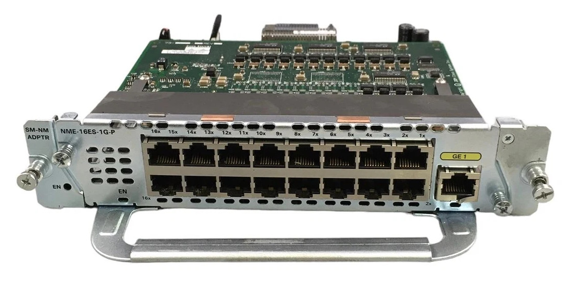
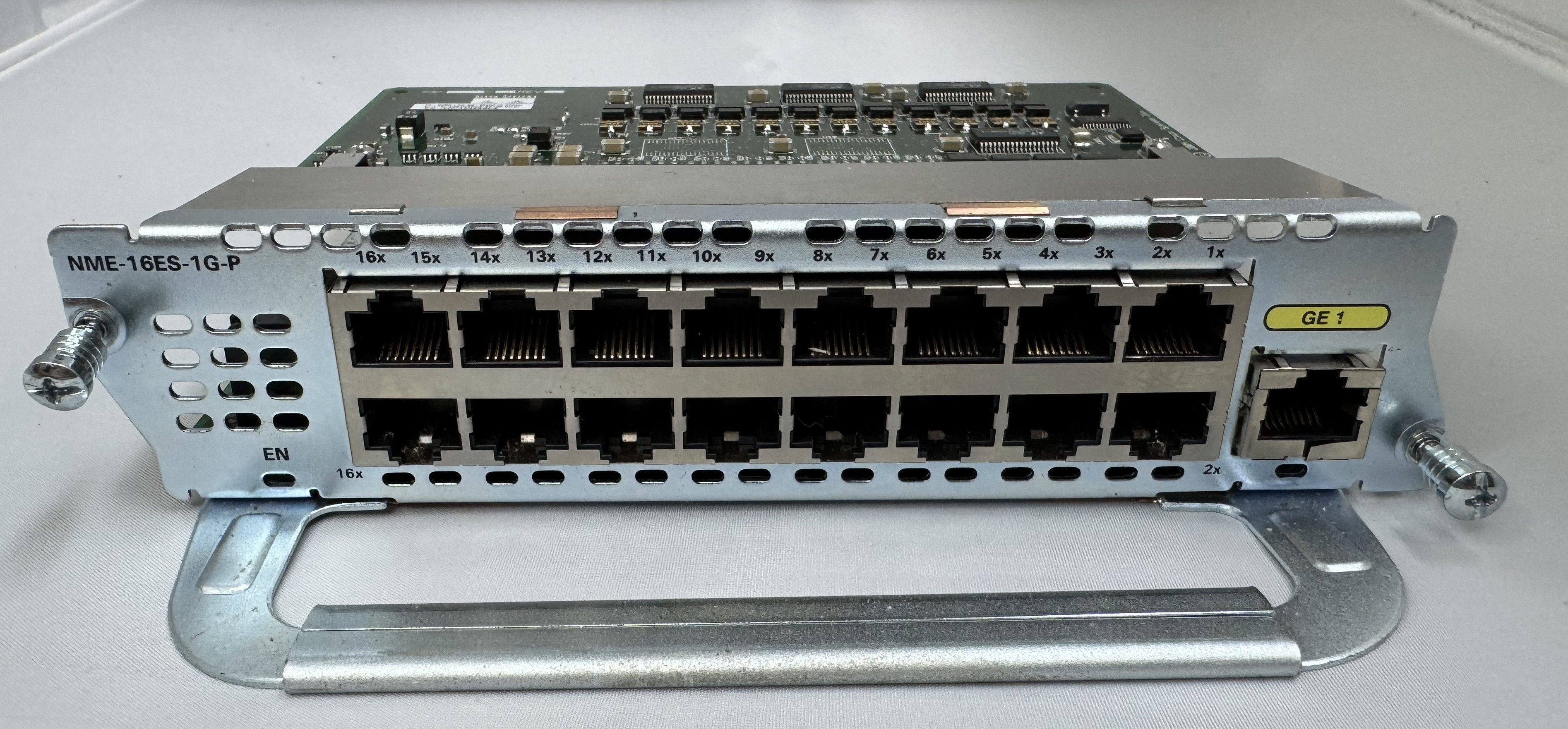
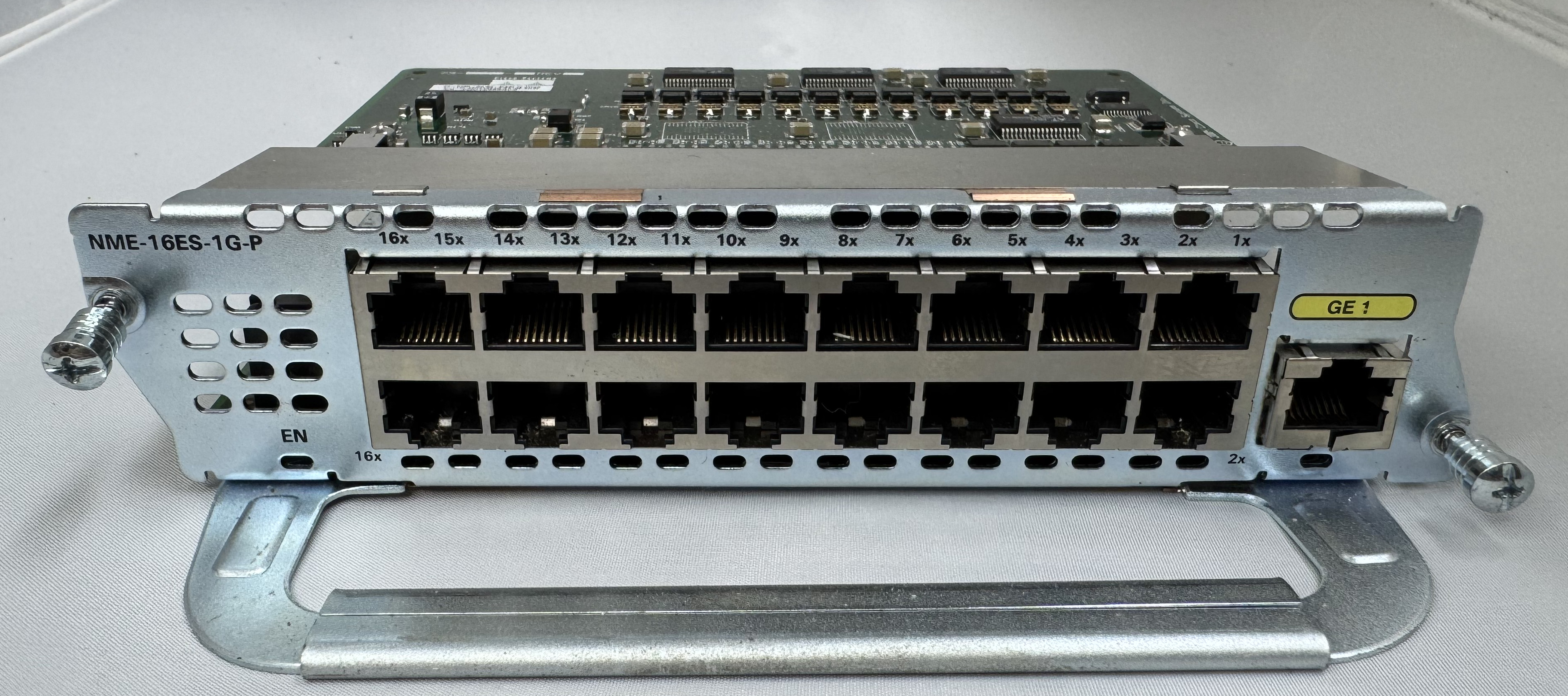
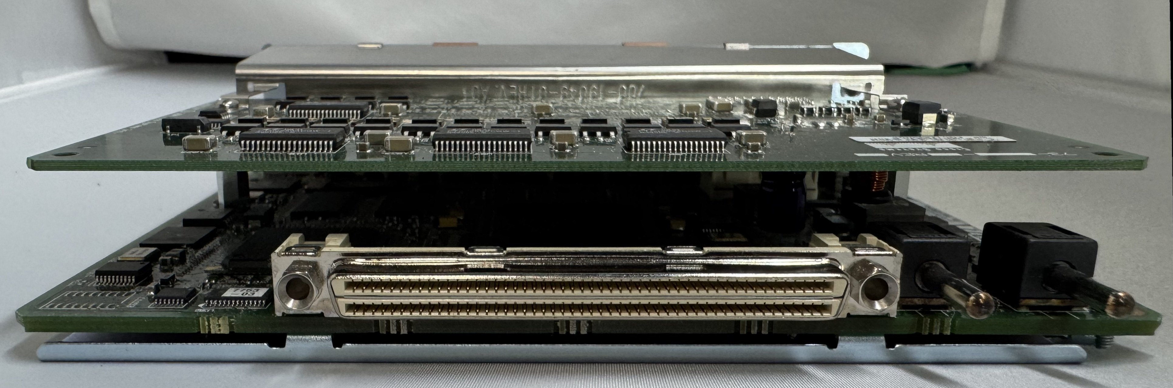
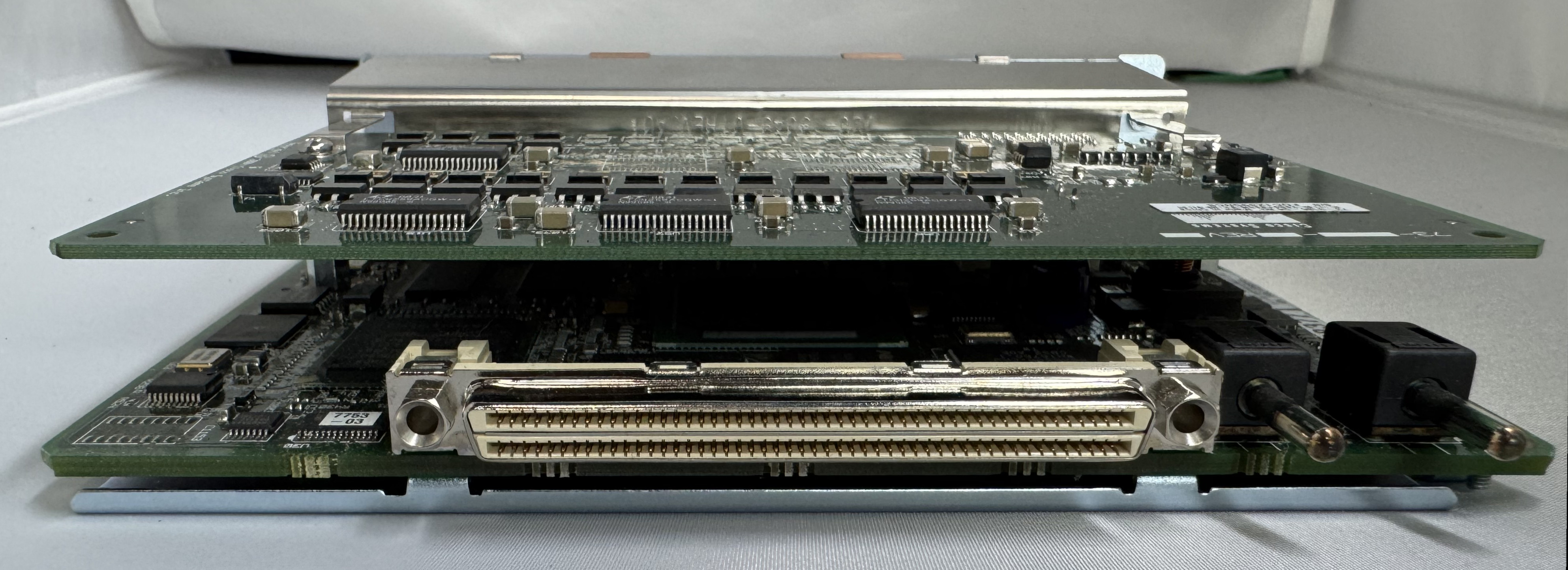
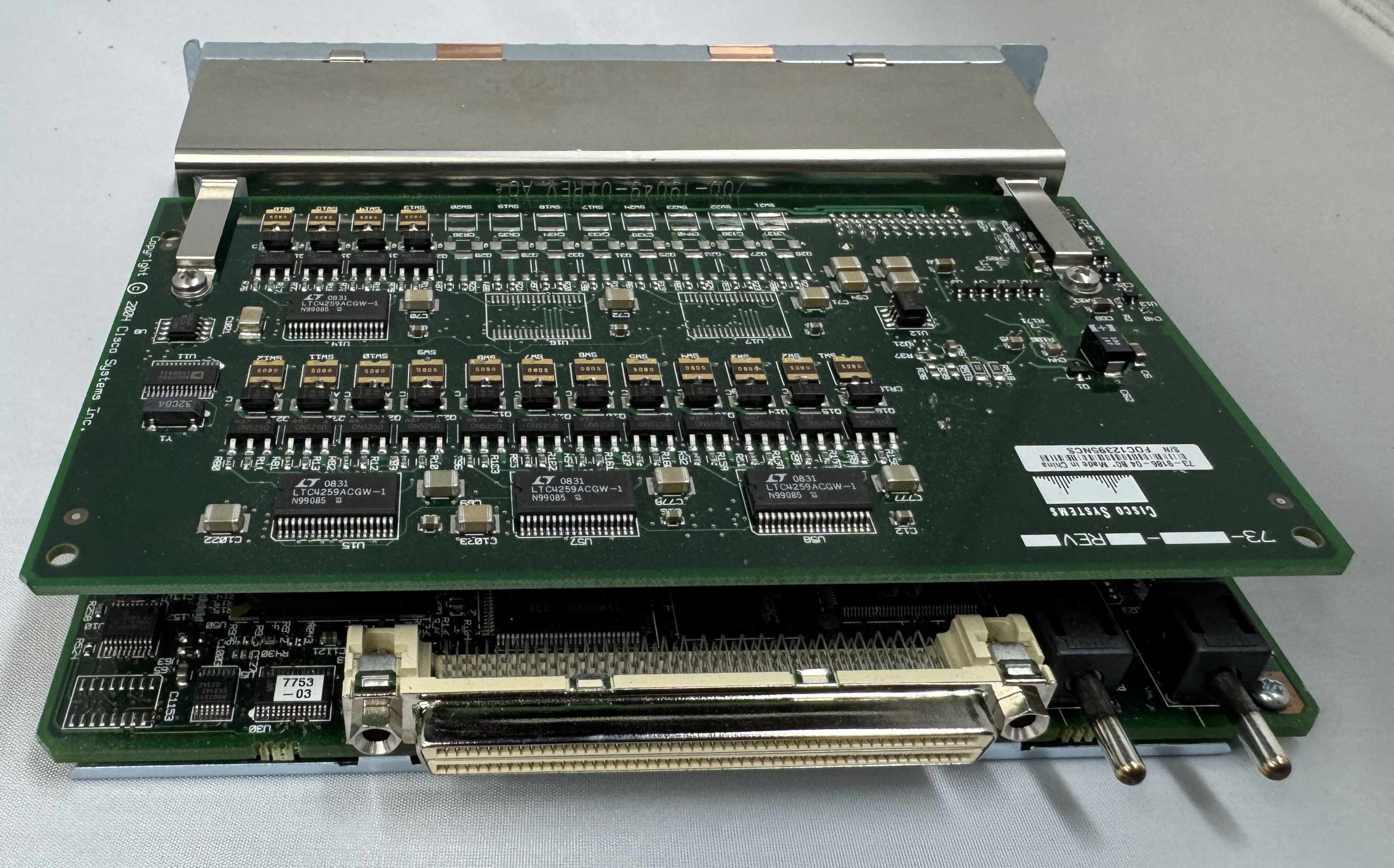
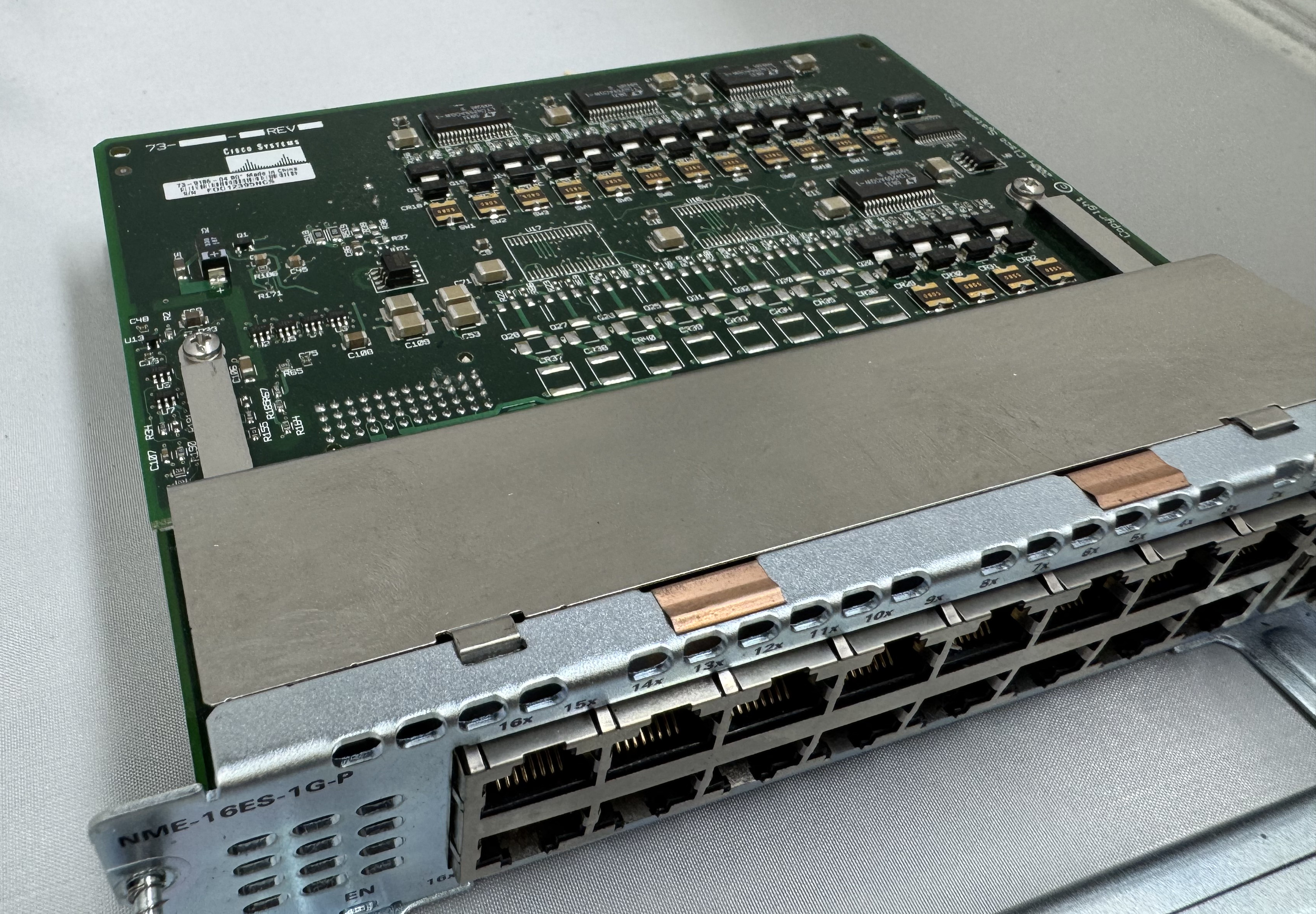
I bought a T1 card because I thought it would be fun to eventually play with. Then I bought a CISCO NME-16ES-1G-P. This is a Cisco Switch as a card module. They are odd. It runs its own OS. It has an internal port to the main system, then to configure any of the 16 x 10/100mb/s or 1 x 1gb/s ports you run ‘service-module gigabitEthernet 2/0 session’ and it opens a serial connection into the controller of this switch. It has a separate login, configuration, and IOS version. At first, I had to password bypass it because someone had left a password on it. I have used it some, but not much. It needs a firmware update. This is my main source of ethernet ports for devices.

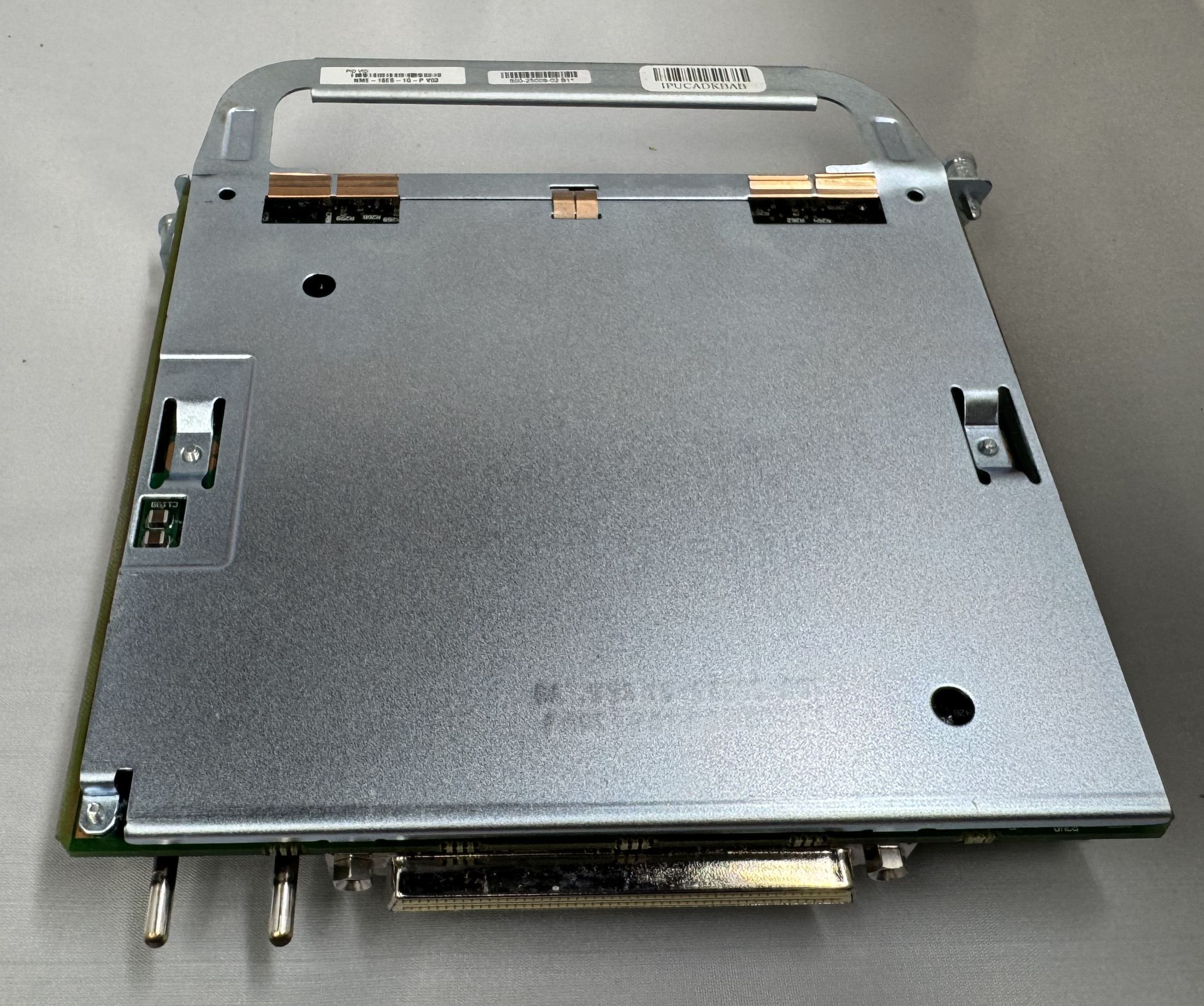
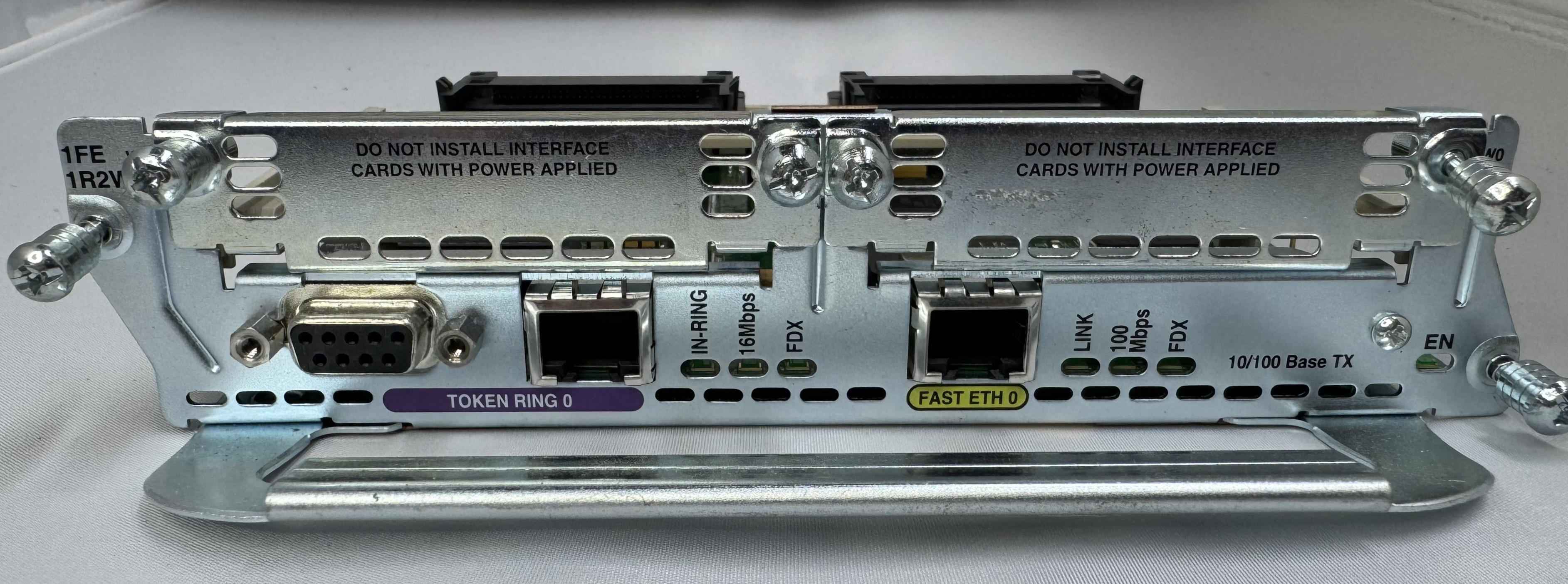
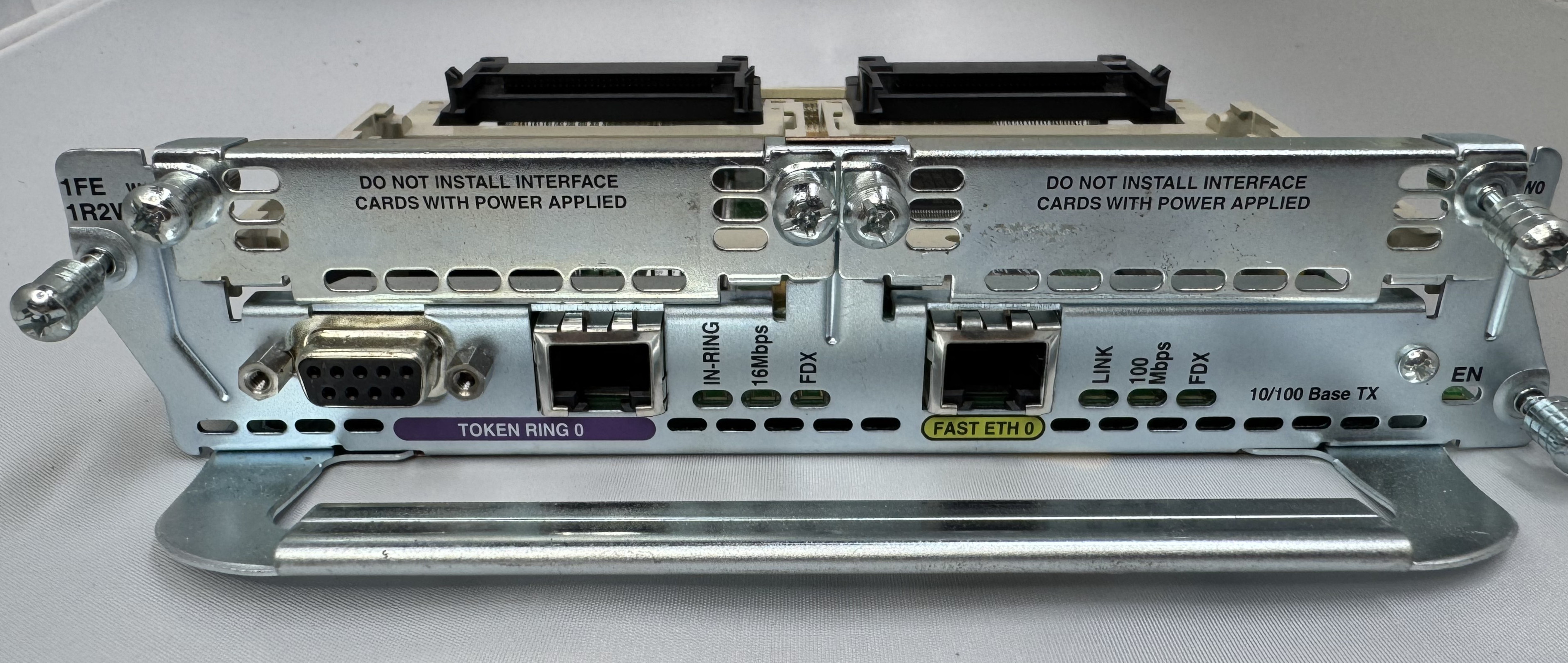
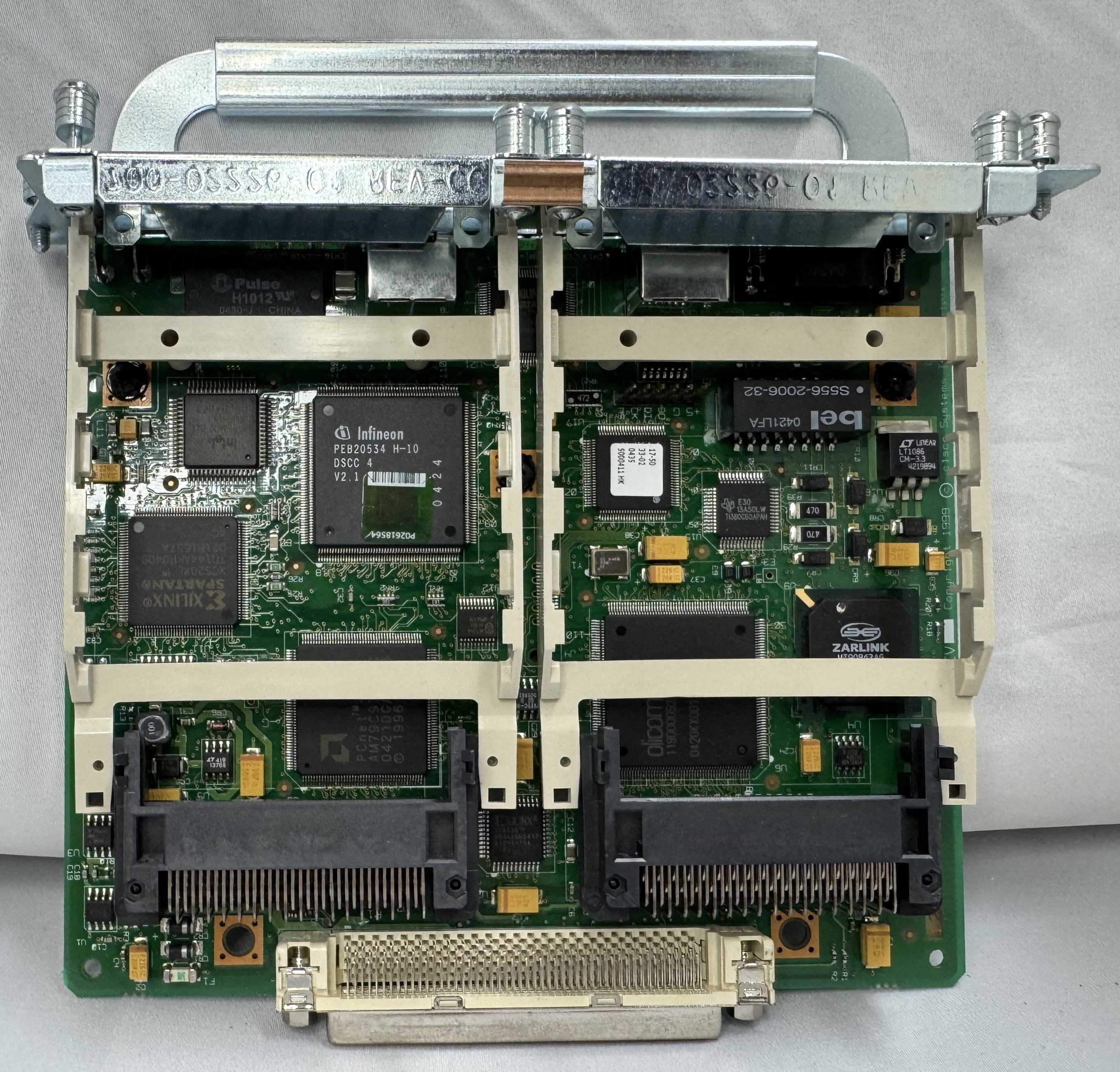
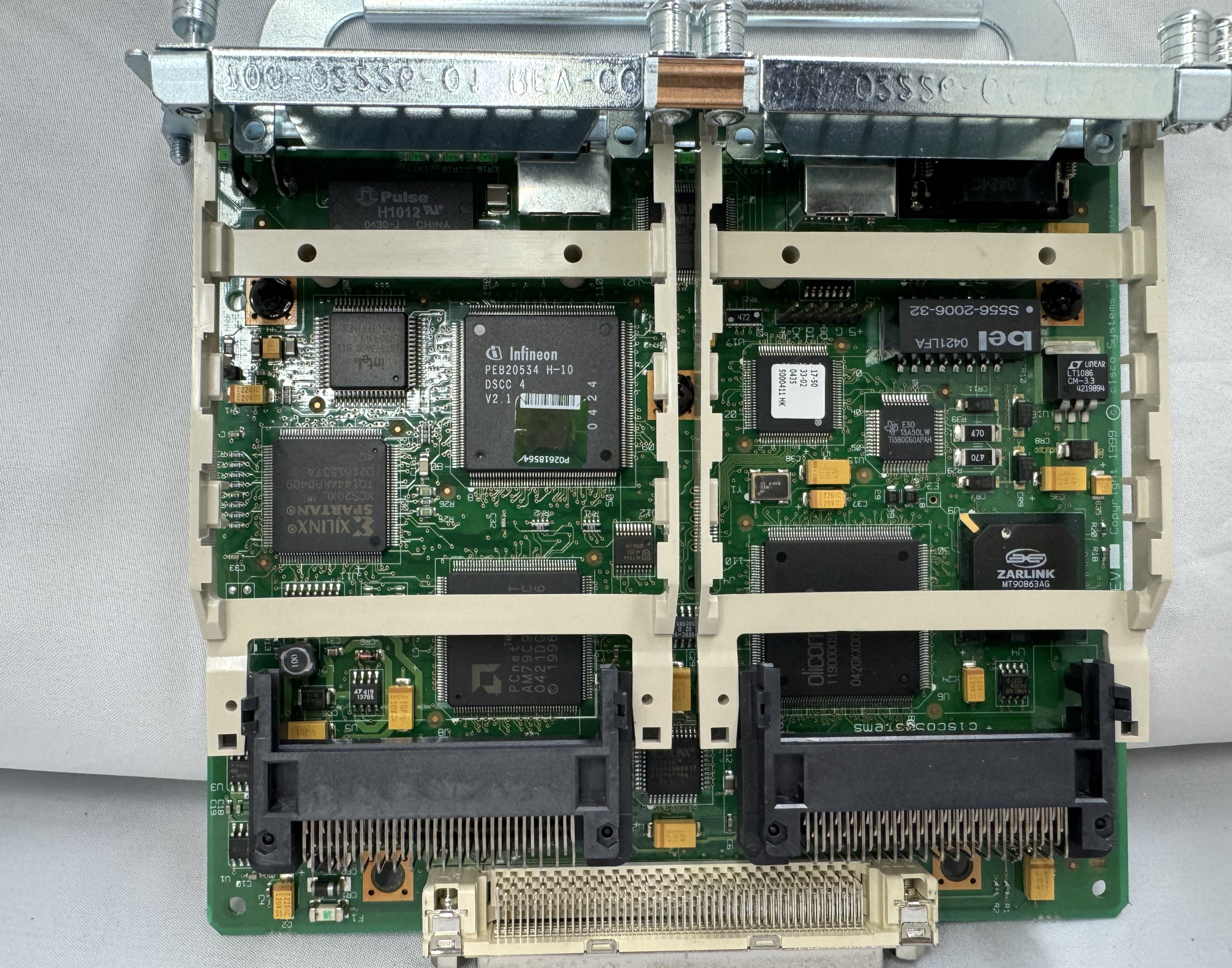
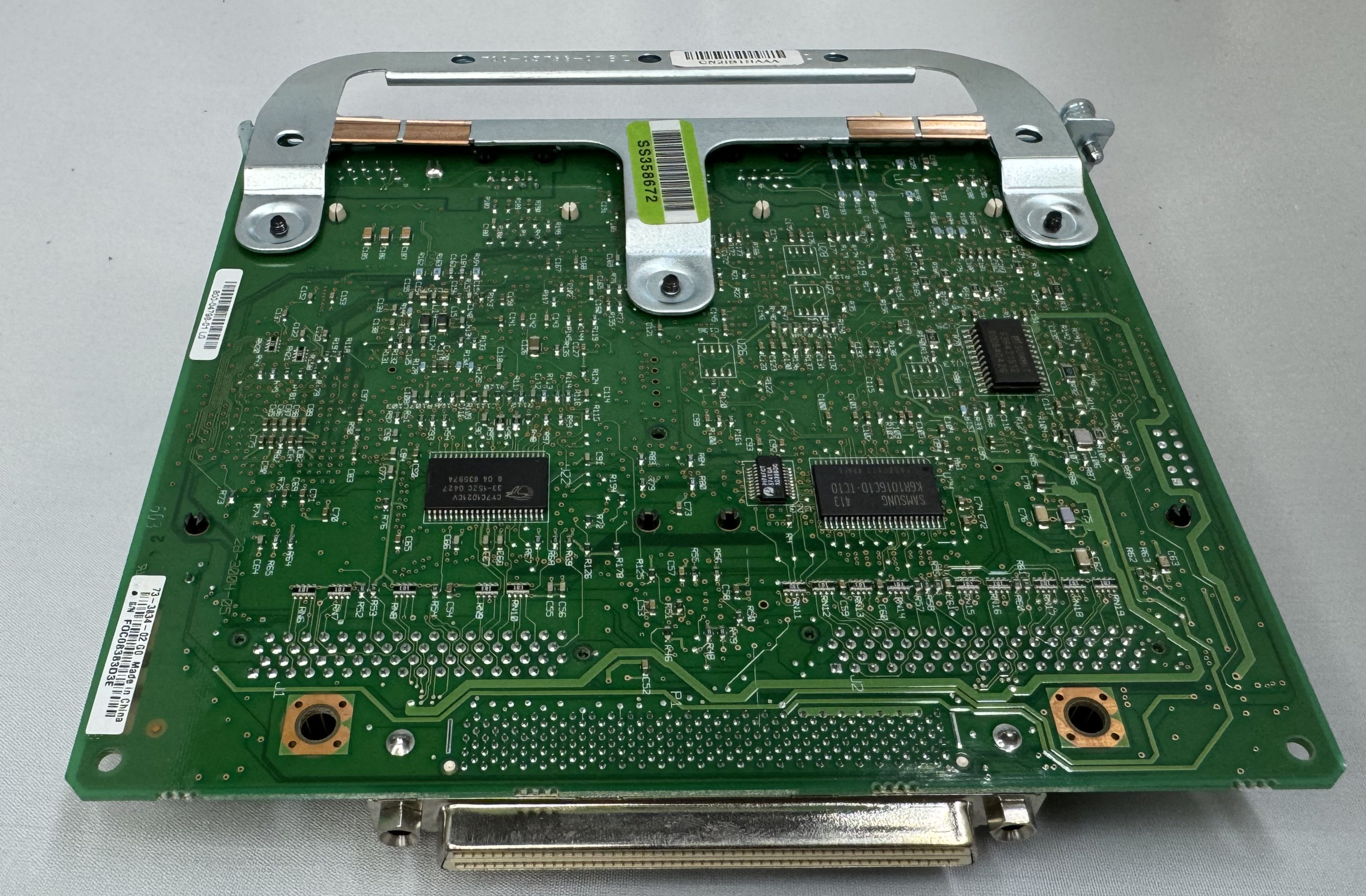
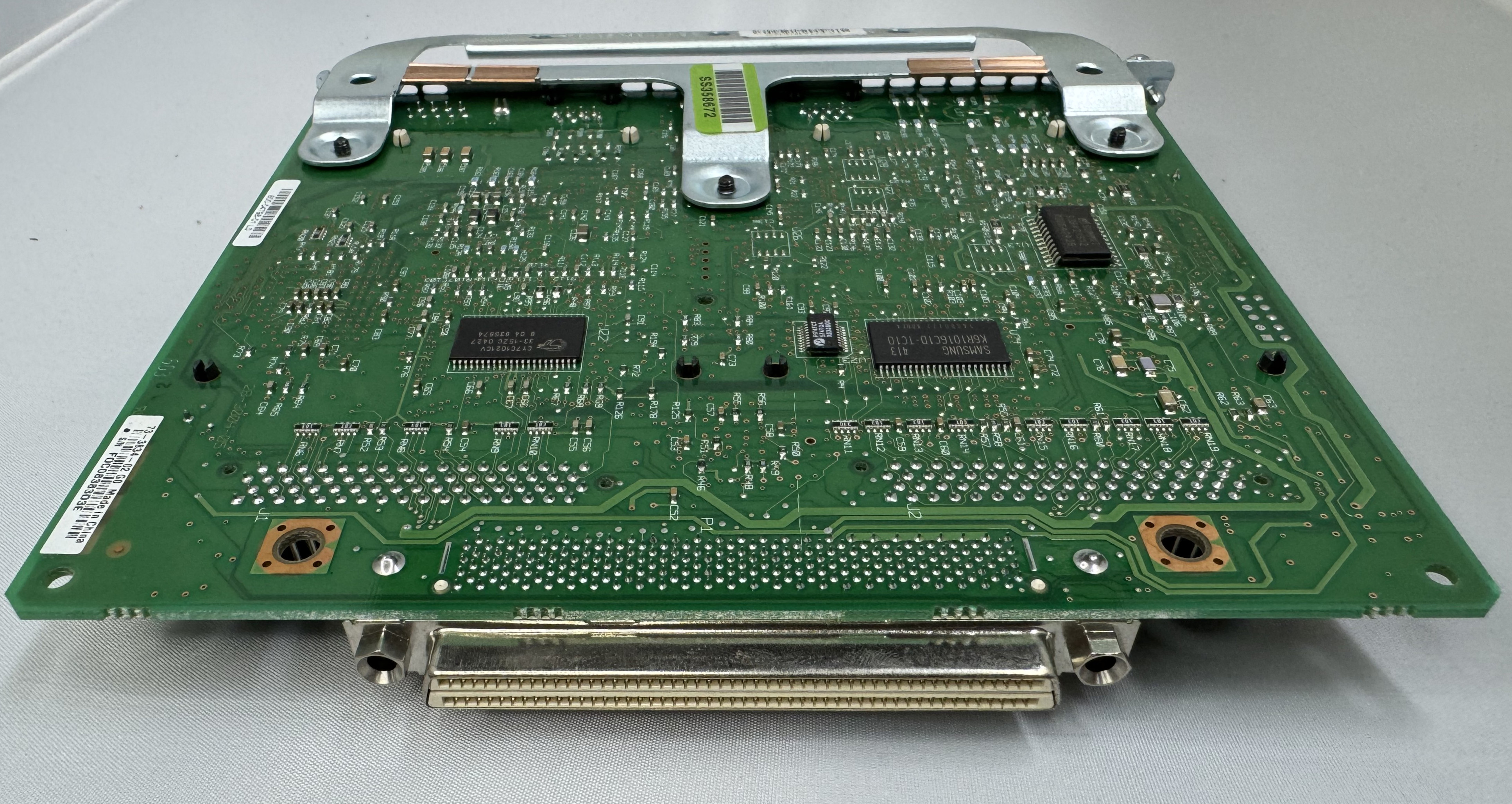
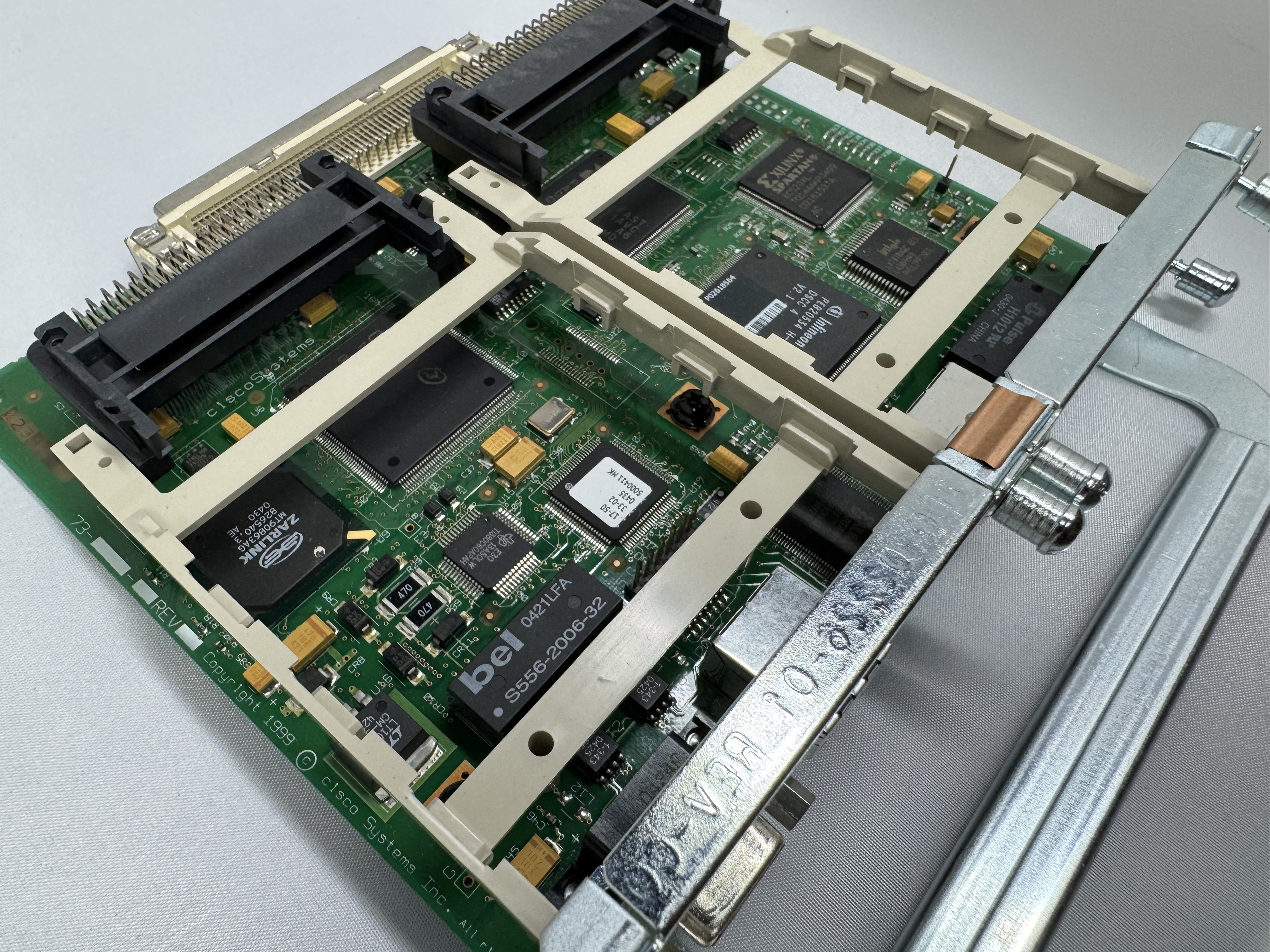
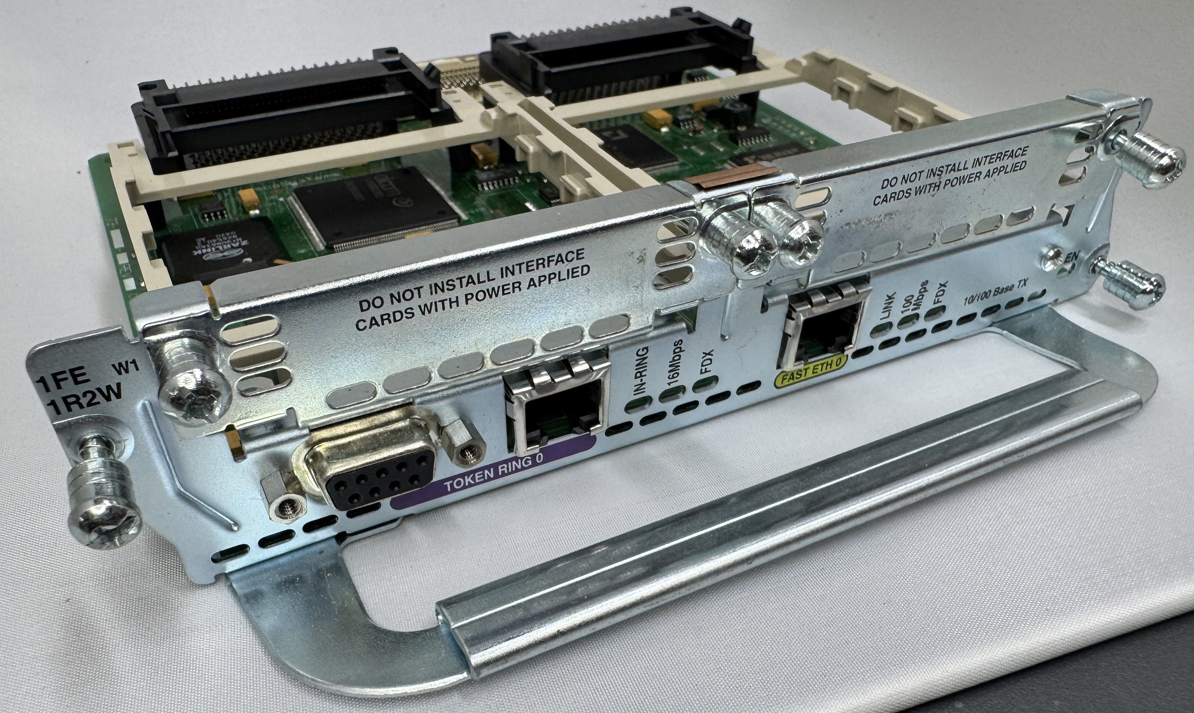
The last card I got is one of the main ones I wanted, a CISCO NM-1FE-1R-2W. This is a 1 FastEthernet (10/100), 1 Token Ring (DB9 or RJ45), and 2 WIC slots. I will do another post on Token Ring later.

Its worth mentioning, for the configuration and tests below, ports 0/0/0 – 3 are our 4FXS ports in HWIC slot 0. In HWIC1 slot (0/1/0 – 1) we have our dual modem card now, a WIC-2AM-v2.

Configuration

As mentioned, you do need a router with the Advanced Services image on it to do voice related features. Once that is loaded, and our hardware was in place, we started configuring the router to move voice data.

We need a pool of IPs that will be given out to clients as they dial in. To do this enter configuration mode and use:

ip local pool dialin-pool 192.168.9.10 192.168.9.20 recycle delay 3600 

You can tell from reading this blog that I have a way too complicated home network. I have the router itself on 192.168.7.0/24, then I made 192.168.9.0/24 for dial in addresses. To be able to send data to them and have them route on my core network, I have RIP running between my home firewall and this Cisco router. When I turn the router on, the routes pop up; when I stop using it for a while, the routes go away. You can set the start and stop of your pool to whatever you like.

dial-peer voice 3 pots 
 destination-pattern 3 
 port 0/0/3 

We need to say how the connection is handled once it comes in the modem. These connections are handled as “line” interfaces from there. We need to tell it this is a dial in line, what its max supported speed is (I just do the max, it will communicate less to the end modem), how flow control will work, and how auth will work.

The line configuration says it beeds ppp, since I do not specify the the auth system, any user is currently allowed… which is great!

line 0/1/0 
 modem Dialin 
 modem autoconfigure discovery 
 transport input all 
 autoselect ppp 
 stopbits 1 
 speed 115200 
 flowcontrol hardware 

Last, we need to configure the IP interface of this line, we do that by configuring the async line assigned to the modem port. This also is where we set which pool will be used for dial in users. I added the ppp timeout command because some of the older systems I have were taking a while to respond.

interface Async0/1/0 
 ip address 192.168.9.1 255.255.255.0 
 encapsulation ppp 
 peer default ip address pool dialin-pool
 async mode interactive 
 no keepalive 
 ppp timeout authentication 30

That is the key configuration needed to get dial up working! Below I will put my full config (minus password) in case any of it helps someone. Leave a comment if this helps you, or you need extra help!

Full Configuration

hostname router 
! 
boot-start-marker 
boot system flash:c3825-adventerprisek9-mz.151-4.M10.bin 
boot-end-marker 
! 
enable secret 0 test
! 
aaa new-model 
aaa authentication login default local line 
!
aaa session-id common 
no network-clock-participate slot 1 
dot11 syslog 
ip source-route 
ip cef 
! 
ip dhcp pool TOKEN 
 network 192.168.8.0 255.255.255.0 
 default-router 192.168.8.1 
 dns-server 192.168.7.1 
!
ip domain name lbt.home.ntbl.co 
no ipv6 cef 
!
multilink bundle-name authenticated 
voice-card 0 
crypto pki token default removal timeout 0 
username admin privilege 15 secret 0 admin
username test privilege 0 password 0 test 
!
redundancy 
!
ip ssh version 2 
!
interface GigabitEthernet0/0 
 ip address 192.168.7.10 255.255.255.0 
 duplex auto 
 speed auto 
 media-type rj45 
! 
interface GigabitEthernet0/1 
 no ip address 
 shutdown 
 duplex auto 
 speed auto 
 media-type rj45 
!
interface Serial0/3/0 
 no ip address 
 shutdown 
 clock rate 2000000 
! 
interface FastEthernet1/0 
 no ip address 
 shutdown 
 duplex auto 
 speed auto 
! 
interface TokenRing1/0 
 ip address 192.168.8.1 255.255.255.0 
 ring-speed 4 
! 
interface GigabitEthernet2/0 
 ip address 100.64.0.1 255.255.255.0 
!
interface Async0/1/0 
 ip address 192.168.9.1 255.255.255.0 
 encapsulation ppp 
 peer default ip address pool dialin-pool 
 async mode interactive 
 no keepalive 
 ppp timeout authentication 30 
!
interface Async0/1/1 
 no ip address 
 encapsulation slip 
! 
interface Async0/2/0 
 no ip address 
 encapsulation slip 
! 
interface Async1/0/0 
 no ip address 
 encapsulation slip 
! 
router rip
 network 100.0.0.0 
 network 192.168.7.0 
 network 192.168.9.0 
 neighbor 100.64.0.2 
 neighbor 192.168.7.1 
!
ip local pool dialin-pool 192.168.9.10 192.168.9.20 recycle delay 3600 
ip forward-protocol nd 
no ip http server 
no ip http secure-server 
! 
ip route 0.0.0.0 0.0.0.0 192.168.7.1 
!
control-plane
!
voice-port 0/0/0
!
voice-port 0/0/1
!
voice-port 0/0/2
! 
voice-port 0/0/3 
!
mgcp profile default 
! 
dial-peer voice 3 pots 
 destination-pattern 3 
 port 0/0/3 
!
telephony-service 
 max-conferences 12 gain -6 
 transfer-system full-consult 
!
line con 0 
line aux 0 
line 0/1/0 
 modem Dialin 
 modem autoconfigure discovery 
 transport input all 
 autoselect ppp 
 stopbits 1 
 speed 115200 
 flowcontrol hardware 
line 0/1/1 
 stopbits 1 
 speed 115200 
 flowcontrol hardware 
line 0/2/0 
 stopbits 1 
 speed 115200 
 flowcontrol hardware 
line 1/0/0 
 stopbits 1 
 speed 115200 
 flowcontrol hardware 
line 130 
 no activation-character 
 no exec 
 transport preferred none 
 transport input all 
 transport output lat pad telnet rlogin lapb-ta mop udptn v120 ssh 
line vty 0 4 
 transport input ssh 
!
scheduler allocate 20000 1000 
end 

The High Nibble Cromemco Z-1 Replica

The High Nibble is back with another fun retro computer kit. This one of the Cromemco Z-1. I reached out to the creator of the kit when it first went up, and he asked if I was sure I was interested. The kit is 99% the same as the IMSAI 8080, including most of the components except the acrylic panel and new firmware. The kits are so similar the PCB for the main board is the IMSAI 8080. I enjoyed the last one so much and wanted to support the creator (not to mention a new kit means more blinky lights on the shelf); thus, I ordered the new kit.

The kits are not cheap at $300, but come with everything you need, including a ready to go controller. The packaging is done well with individually slotted spots for each switch and IC in cardboard. The metal case is a nice touch. And just like before, the firmware is fantastic. You get a full web interface, external serial ports, the gorgeous front panel, and the system can update over the air update via Wi-Fi.

I won’t go too in-depth about the kit because it is so similar to the other one. The soldering is not too bad, the process starts with one small IC that has to be soldered in the front of the pcb, after that things like sockets and LEDs are easy, large, and straight forward.

I got a new soldering iron, the Pinecil from Pine64. This was my first project using it and I found it delightful. It’s smaller than my old iron, making it easier to handle. It’s advertised as a “smart” soldering iron which means when you put it down in a holder it quickly cools when not in use. A very nice safety feature.

The parts of the last build that were difficult are here too, having to put the system together as a sandwich of acrylic and circuit boards it’s a bit tricky, but once you get it in the right spot tightens up easily. Tape helped keep the build aligned during assembly.

The website for the project has a lot of good information, https://thehighnibble.com/cromemcoZ1/. There’s also a helpful YouTube video, same one as the IMSAI kit, that walks through the construction step-by-step.

The main step that gave me an issue was when you get to Testing, the LS2 light would not come on. After looking in the forums, https://github.com/orgs/thehighnibble/discussions/120, turns out that is a difference in the firmware, and it is not supposed to come on. With the video being for the other kit, it is not mentioned.

Overall, another great kit, and another fun system to add to the collection!