LAN Before Time

Homelab Dial-Up Networking for Retro Computing

I started mentioning about my LAN Before Time project before. The idea is to have a rack of the most diverse CPU, OS, and Networking technologies I can find. Each computer and piece of equipment bringing something new and unique to the collection. One part of this collection was the network. Coming from a networking background, I also wanted to have the most diverse set of networking technologies that I could. To do this I would need to find a core router that could talk all the different protocols I wanted. Having worked at Cisco in the past, I knew they had gear that went back in time, and could add in some additional fun like AppleTalk. That is where I started my search.

Why the Cisco 3825

I knew I needed a Router and not a switch, because we would be going between several protocols. I could time box the router a bit because I wanted to support AppleTalk and IPX. Support from these no longer exists, and thus would give a cutoff for devices I could get.

Years ago, I was the Cisco 7200 VXR guy at work. They were great routers, that could go up to gigabit and go in and out of a ton of different connections, including some voice ones. The issue was they could do lines like T1, but they couldn’t host an analog modem, and that was one thing I very much wanted.

Now we are getting down to a select group of Cisco devices. I started making a table of the pros and cons of each. I also was hoping for something slightly newer to have 1gb/s links available, and hoping that it wouldn’t use a 1000 watts at idle.

This is a table I made of all the different options for routers and the features they supported:

Model (U) Small Bays Large Bays Token Ring IPX / AppletalkDial-Up Base Speed EOL Date Flash
2513 (1) 10mb Before time Internal?
3640 (2)Y / Y100mb 2008-12-31 PCMCIA
3725 (2)Y / Y100mb 2012-03-31 CF
3745 (3)Y / Y100mb 2012-03-31 CF
3825 (2)Y / Y1000mb 2016-11-1 CF + USB 
3845 (3)Y / Y1000mb 2016-11-1 CF + USB 
3945 (3)N / N1000mb 2022-12-31  
7206XVR (3)Y / Y1000mb 2017-02-28? CF/PCMICA 

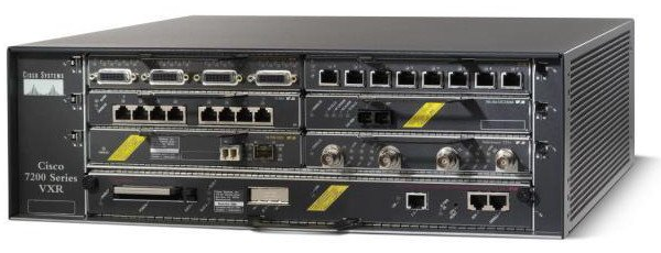
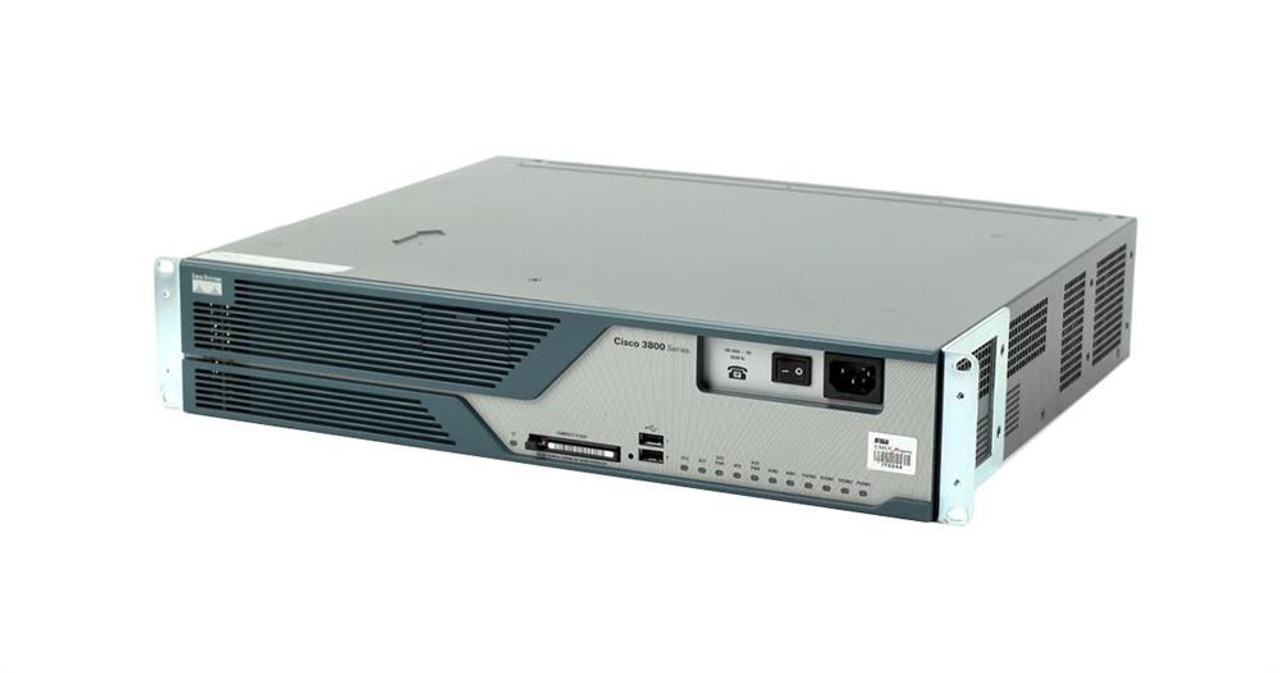
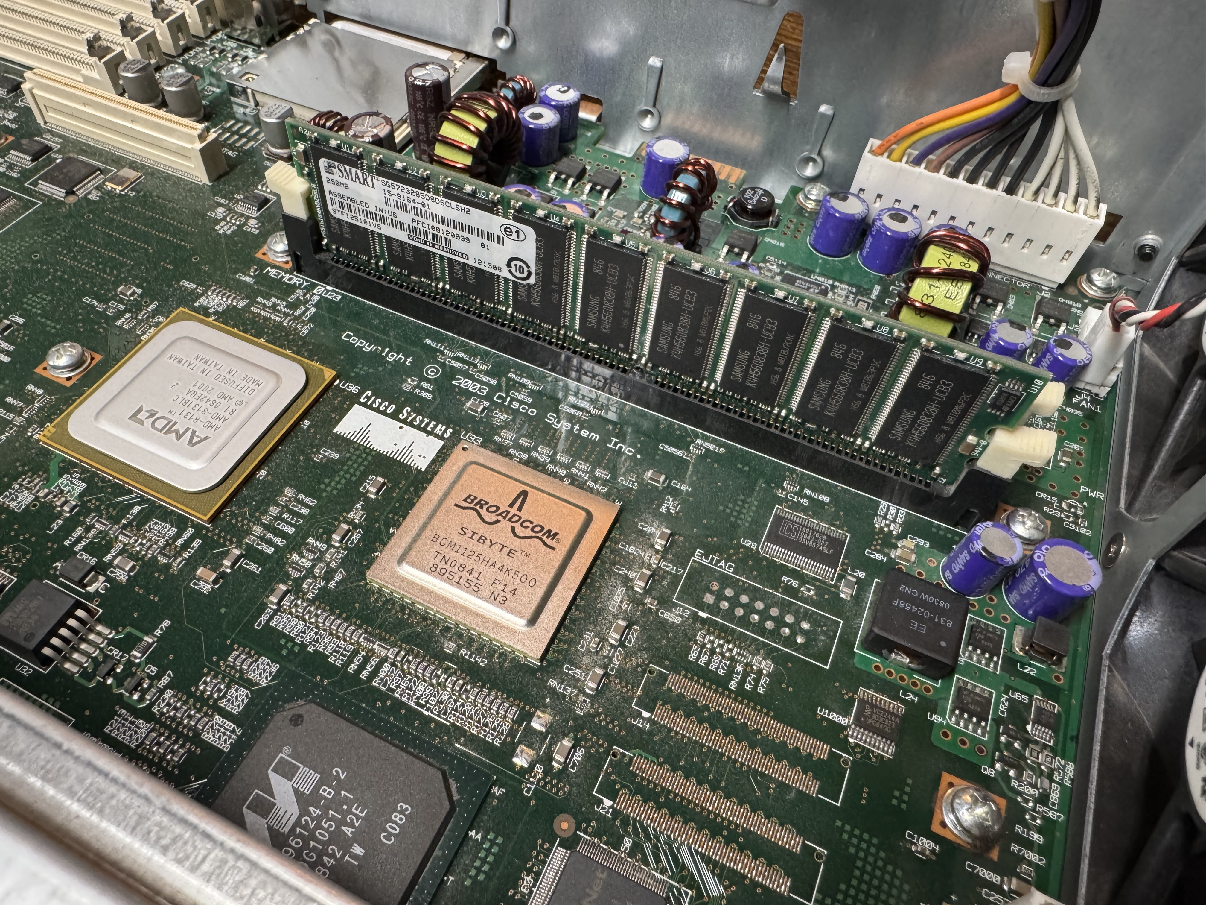
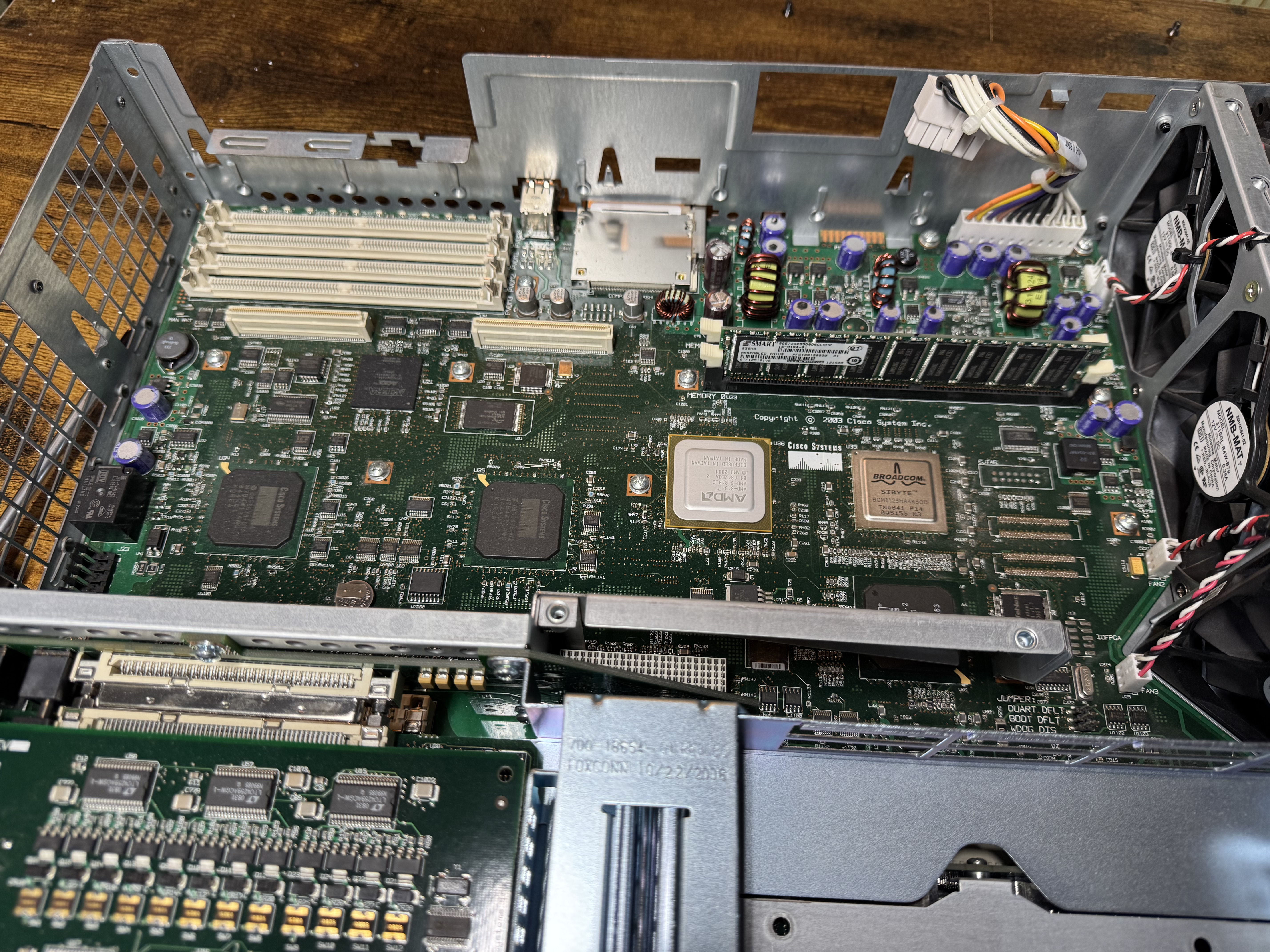
The Cisco 1800/2800/3800 line all came out around the same time, they were considered the G1 generation routers. Things before them were legacy, and the systems after them like the 3945 were the G2 devices. G2 was a step to get rid of legacy, this means dropping AppleTalk, IPX and some of the things I was interested in. By this point I had realistically narrowed down to a Cisco 3725 or 3825. The 3825 had gigabit on the main controller, allowing my to get a little closer to modern systems; that put me over the edge for it. I also was not interested in its giant cousin, the 3845; the 3825 had enough bays and should be quiet enough for me to run routinely.

Cisco 3825 Back

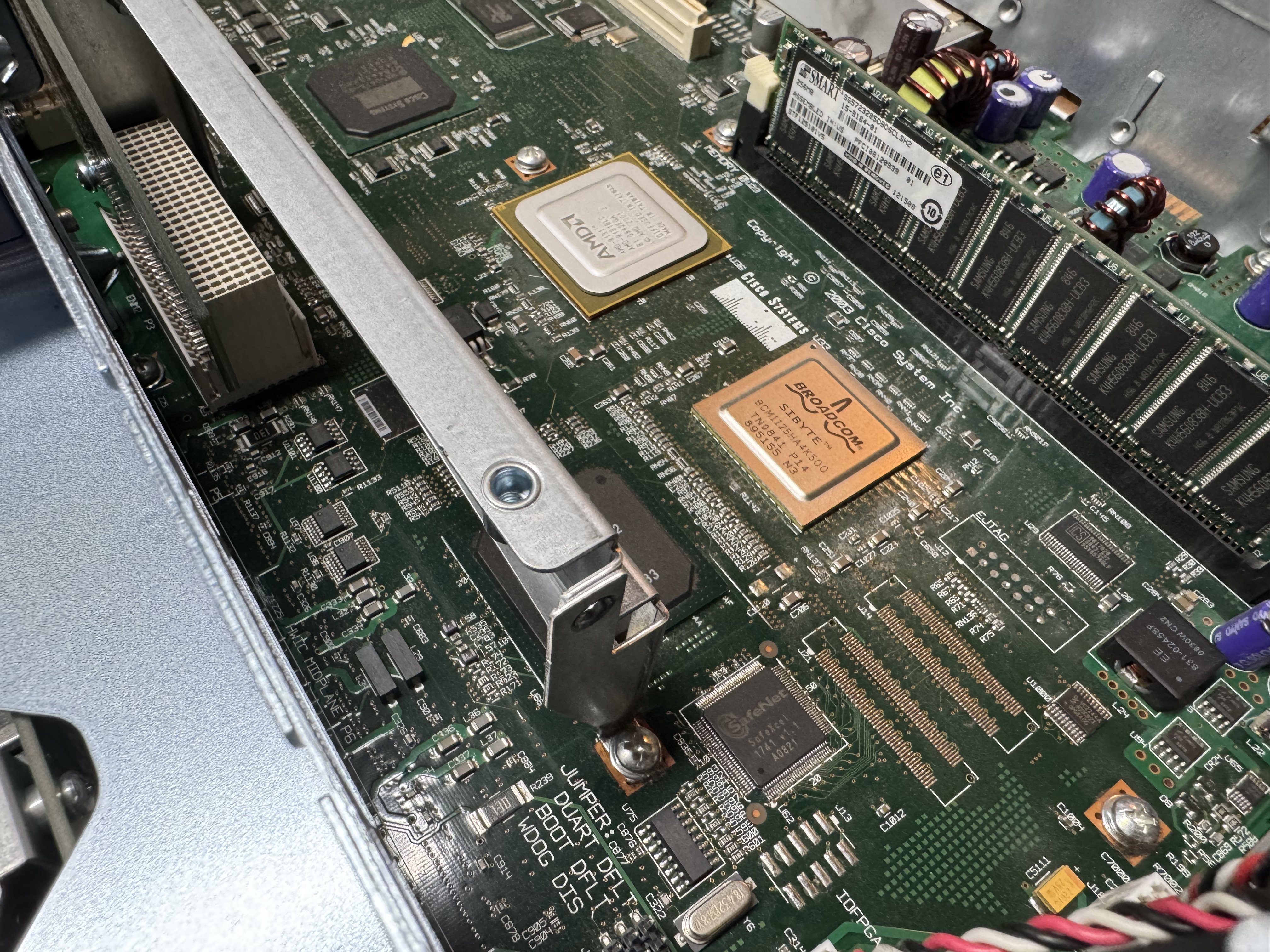
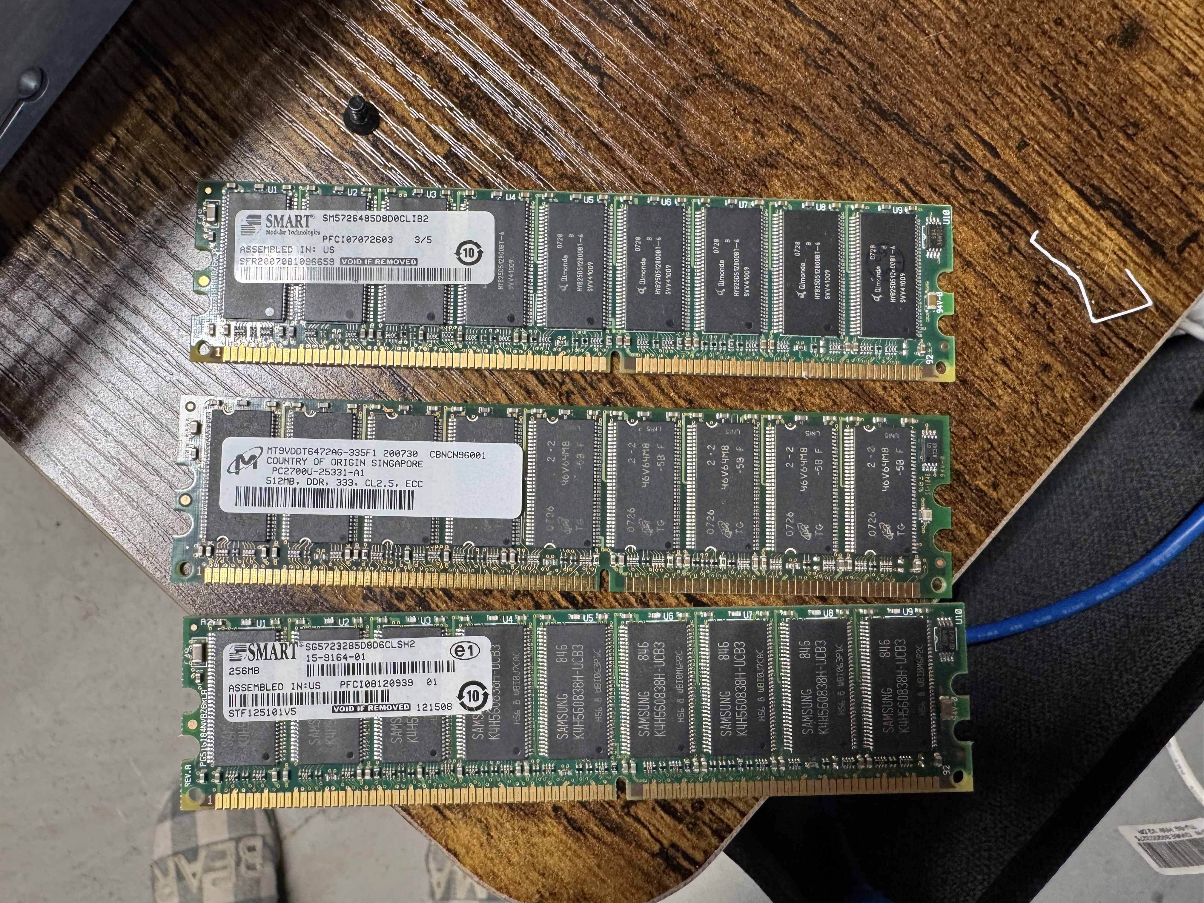
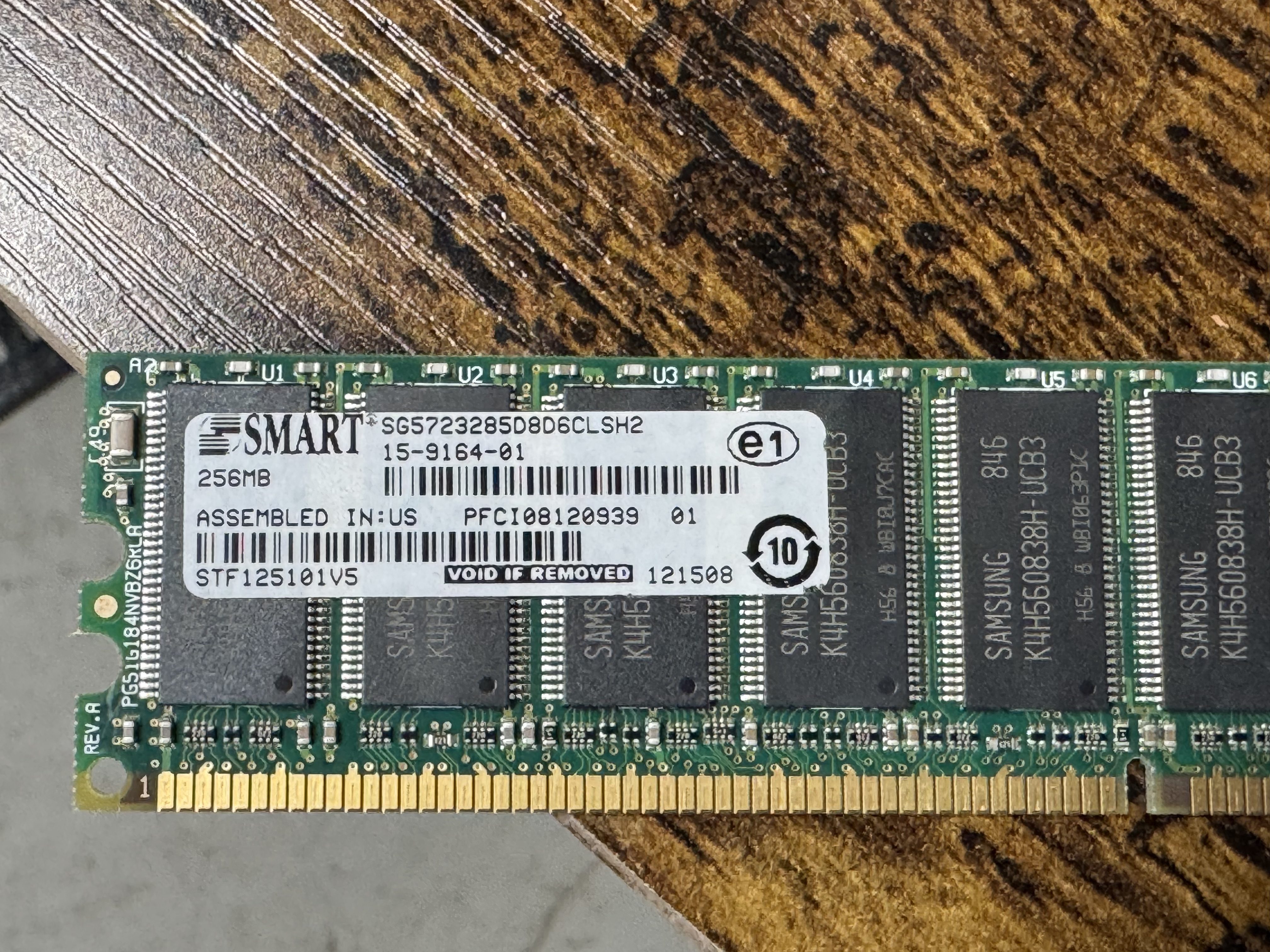
In searching for the voice features I wanted, I found I would need the Advanced Services image loaded, and that required a minimum of 512MB of memory. I ordered a system with Advanced Services and 1GB of memory, the max! When it came it had 256MB! I emailed the seller and he mailed me the proper 1GB of RAM. Once I installed it, the system would boot loop, I found one of the 2 sticks was bad. I ended up putting in one of the 512MB sticks he sent, and the 256MB one it came with for a total of 768MB of RAM.

Upgrading the Cisco 3825

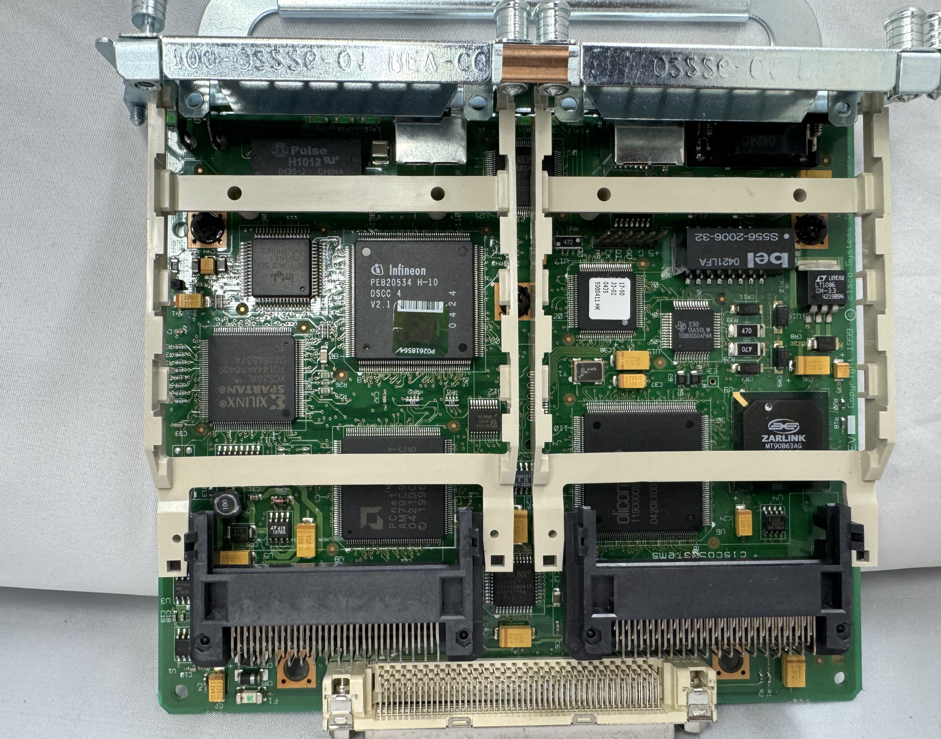
Once I had the device on order, I started learning about the world of voice. I had not done much with voice before, there was a lot to learn. First, I needed to know which cards I would need. The 3825 can run older WIC cards, and the newer high speed HWIC cards. I needed analog modems, and to host those, I needed FX-S/FX-O cards. In learning about them: FX-S Foreign Exchange Station, FX-O Office. The office is for a branch office dialing OUT. You usually want FX-S because it provides a dial tone to dial into. S is to get a dial tone and you can call INTO. O is it receives a dial tone.

I got 4 FX-S Ports. One port is used to dial into, another to route the call out. I need more ports than you would think because of this. I got a CISCO VIC3-4FXS/DID, this gives 4 ports in/out. 2 CISCO WIC-1AM-V2, giving 2 modems I can dial into. There are cards that are 2 modems in one card, but they are rare and expensive. (I would get one later)

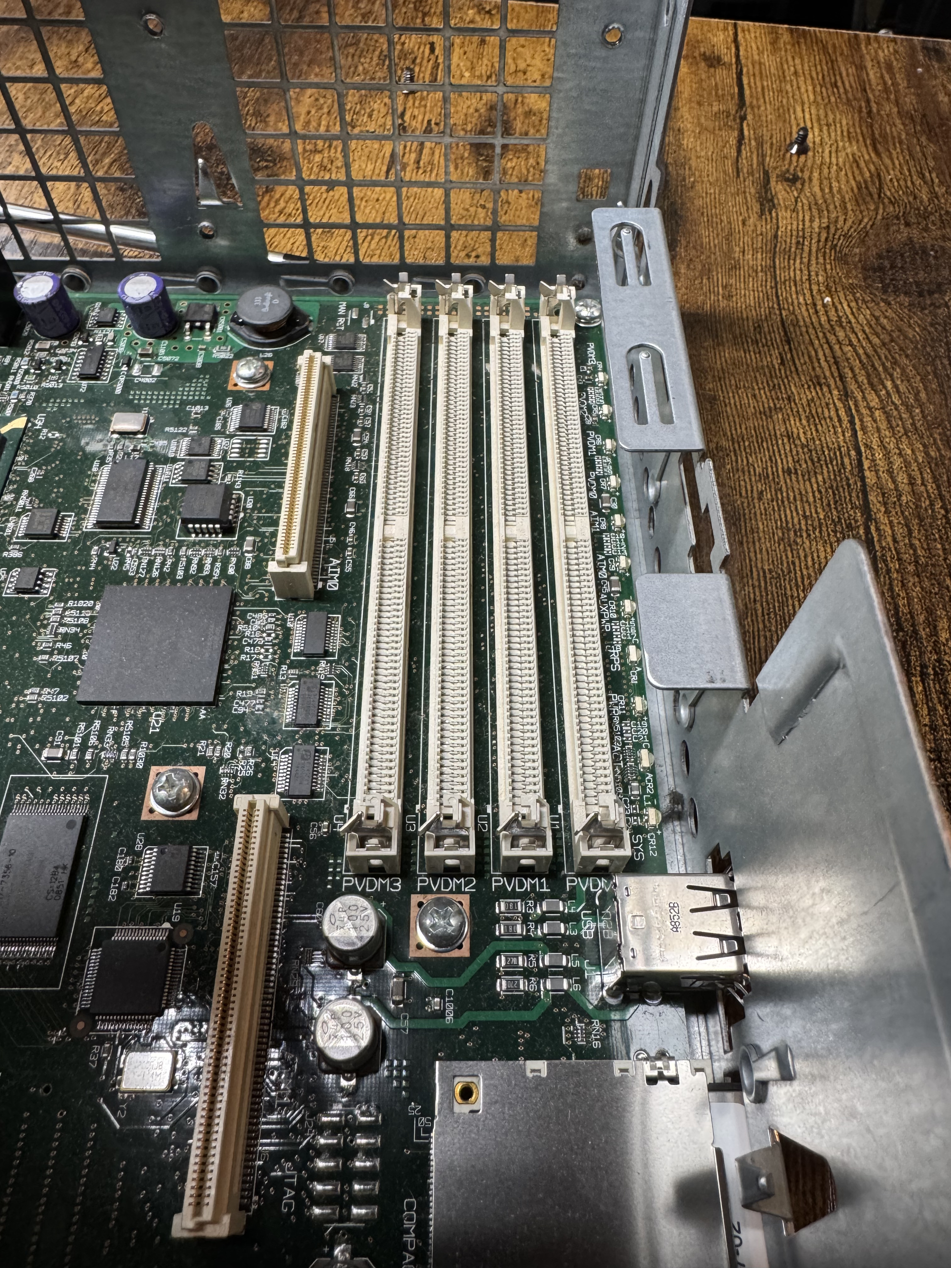
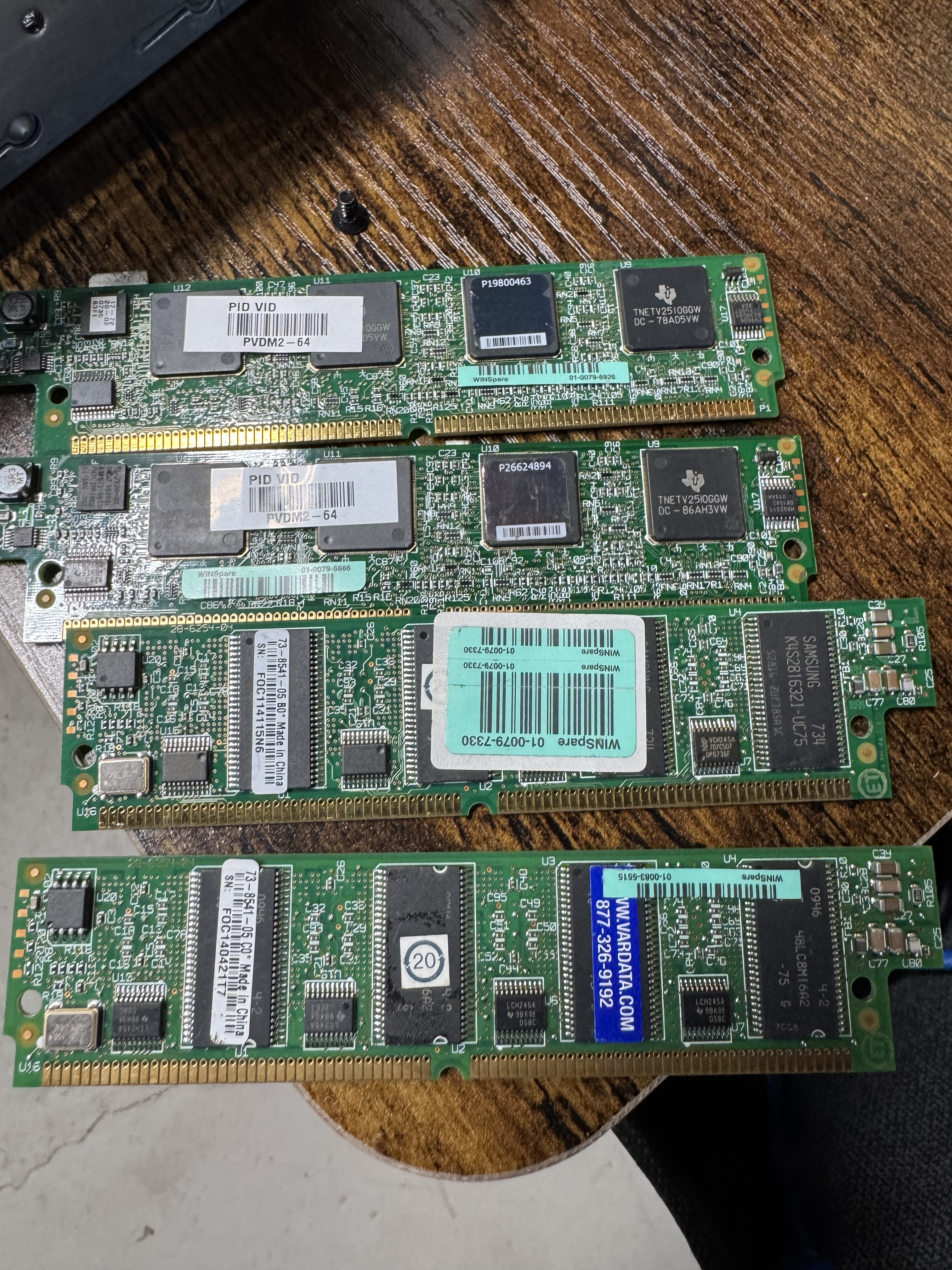
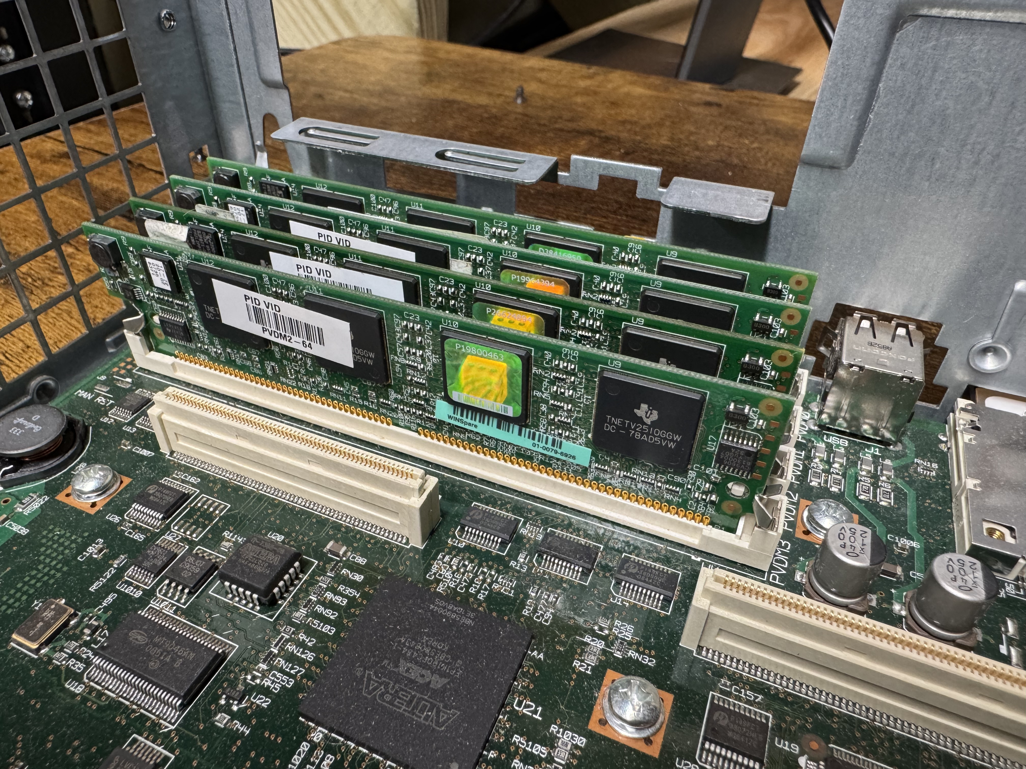
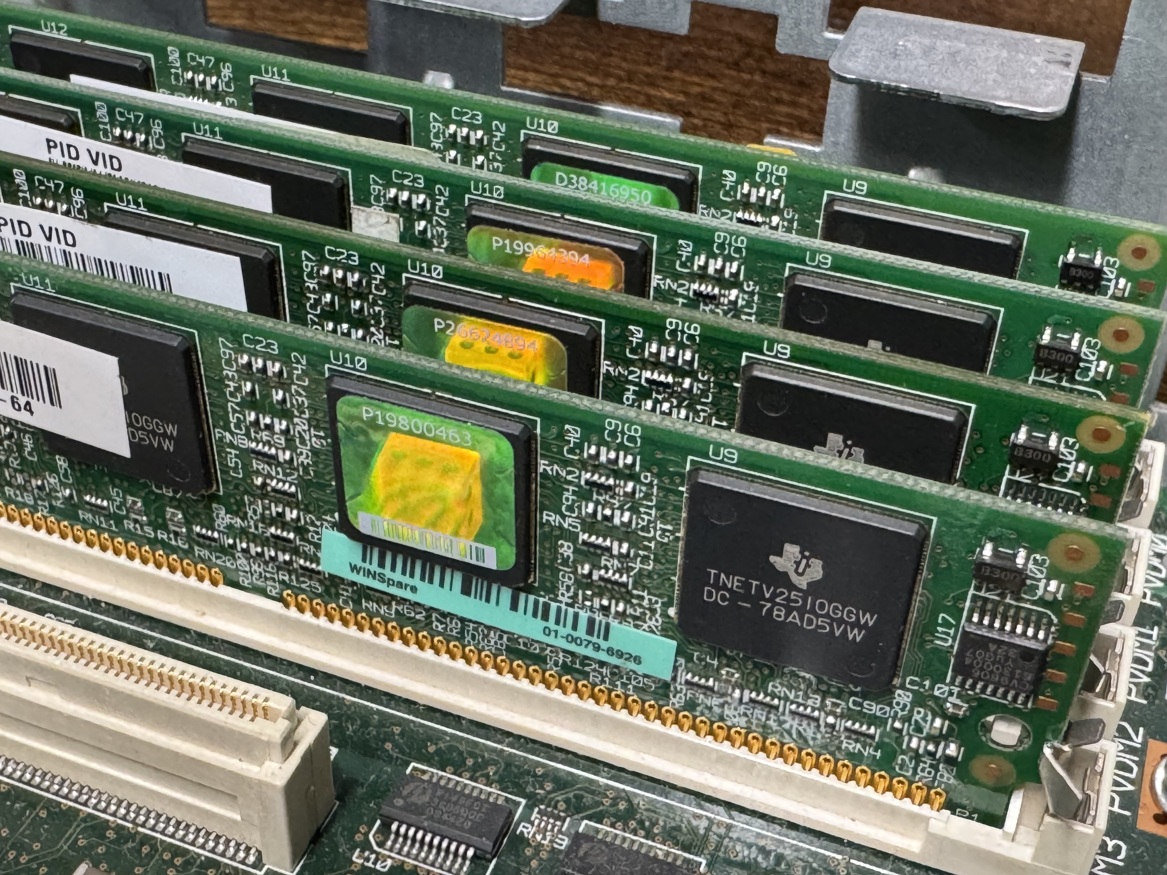
The system now has 768MB of memory, but I would also need PVDMs; Packet Voice Digital Signal Processor (DSP) Module (PVDM2). I had not worked with these before. They are ASICs that come process voice channels. They come in different numbers of channels, PVDM2-8, PVDM2-16, PVDM2-32, PVDM2-48, PVDM2-64. They were cheap, obviously I got 4 PVDM2-64 to go to 256 voice channels for $20 USD. The math is odd here, there are different complexity channels and some knock you down to 1/2 or less of the listed available channels. A “high complexity codec” can make an 8-channel card only handle 4 or less channels. Like I said, these were cheap, so I got 4 256-Channel cards. The cards go into slots that look like DIMMs.

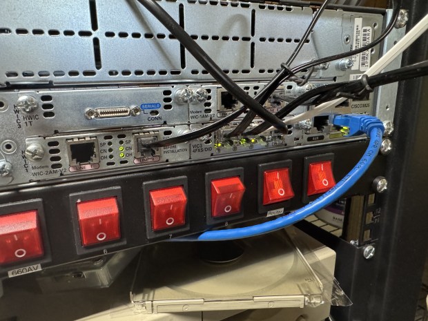
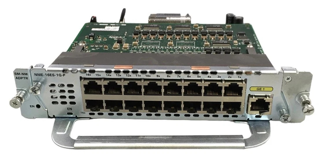
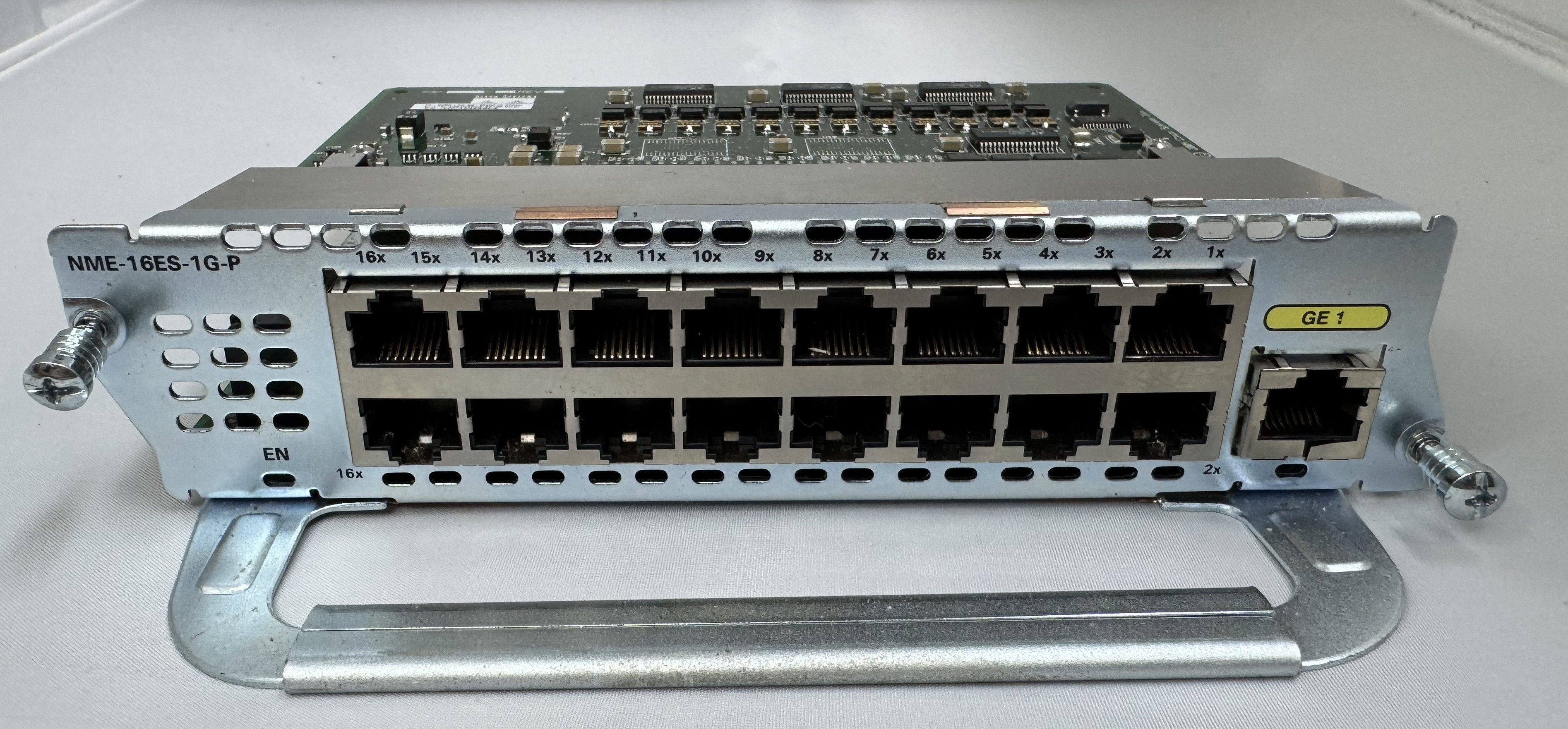
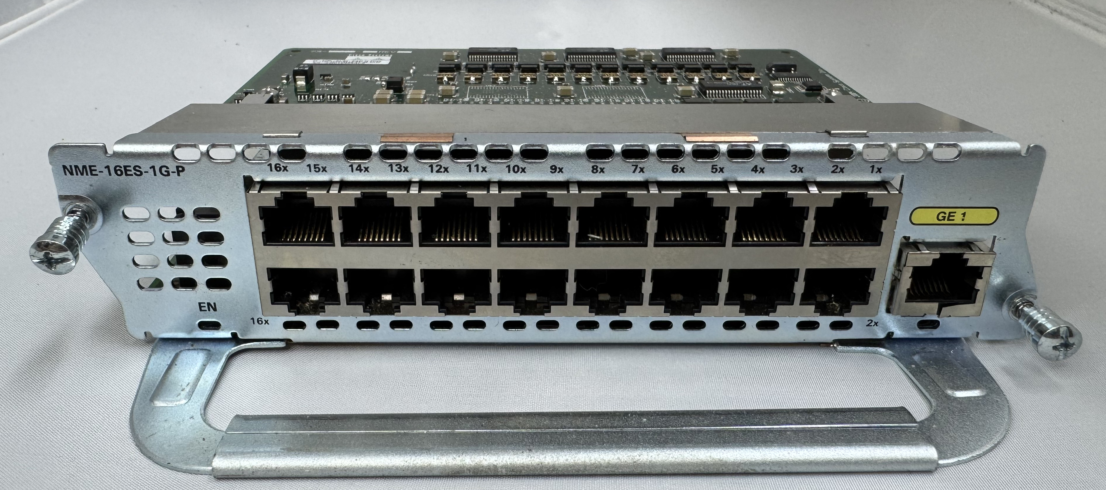
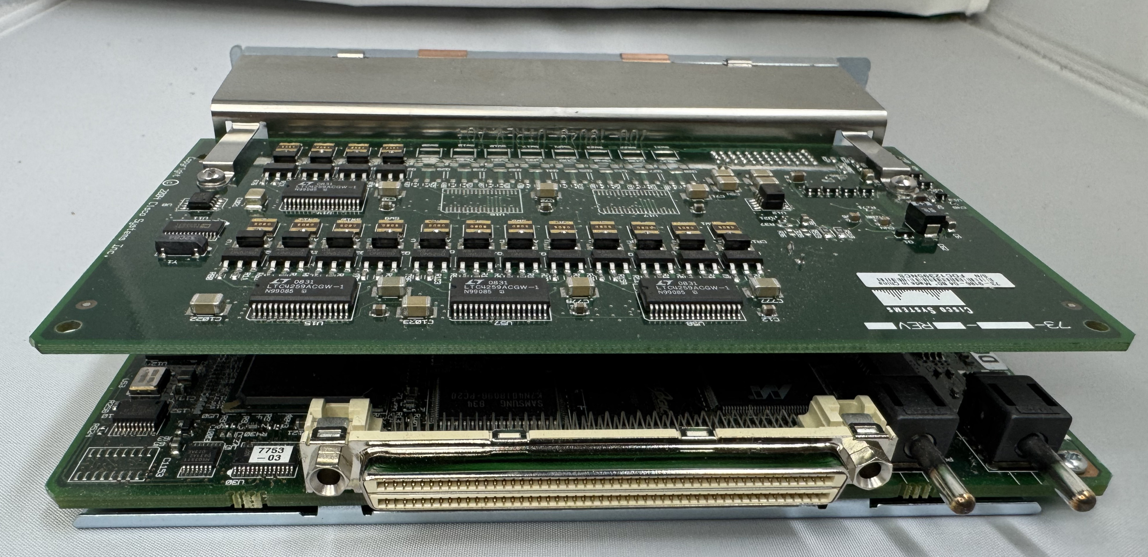
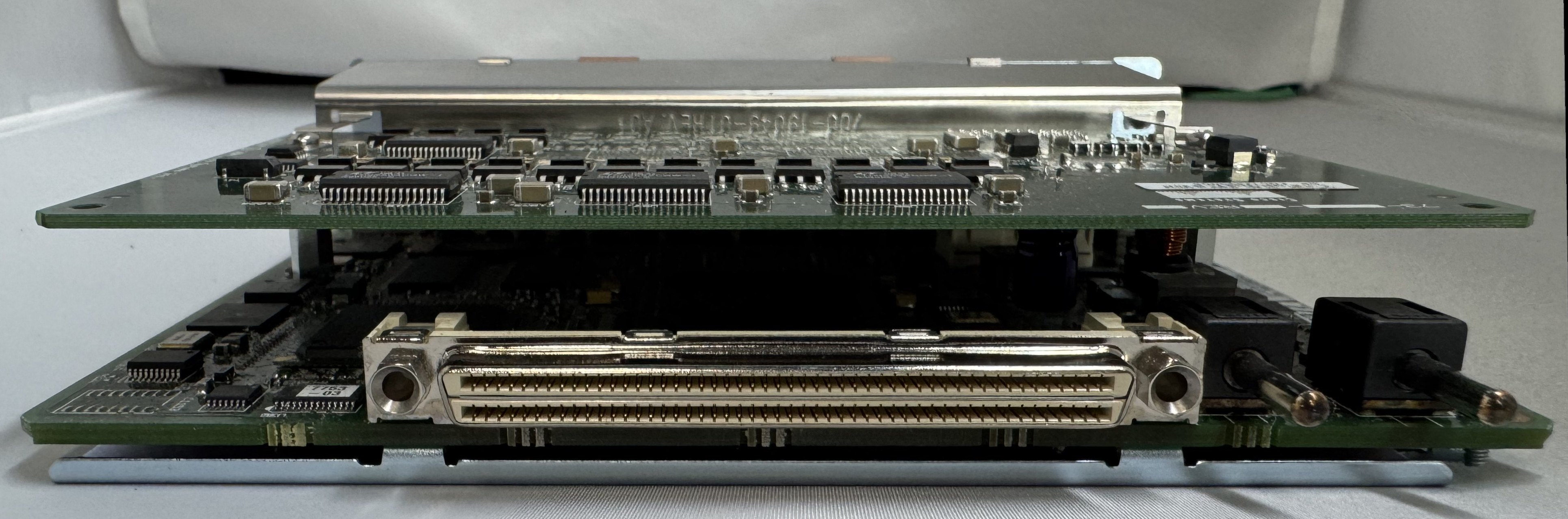
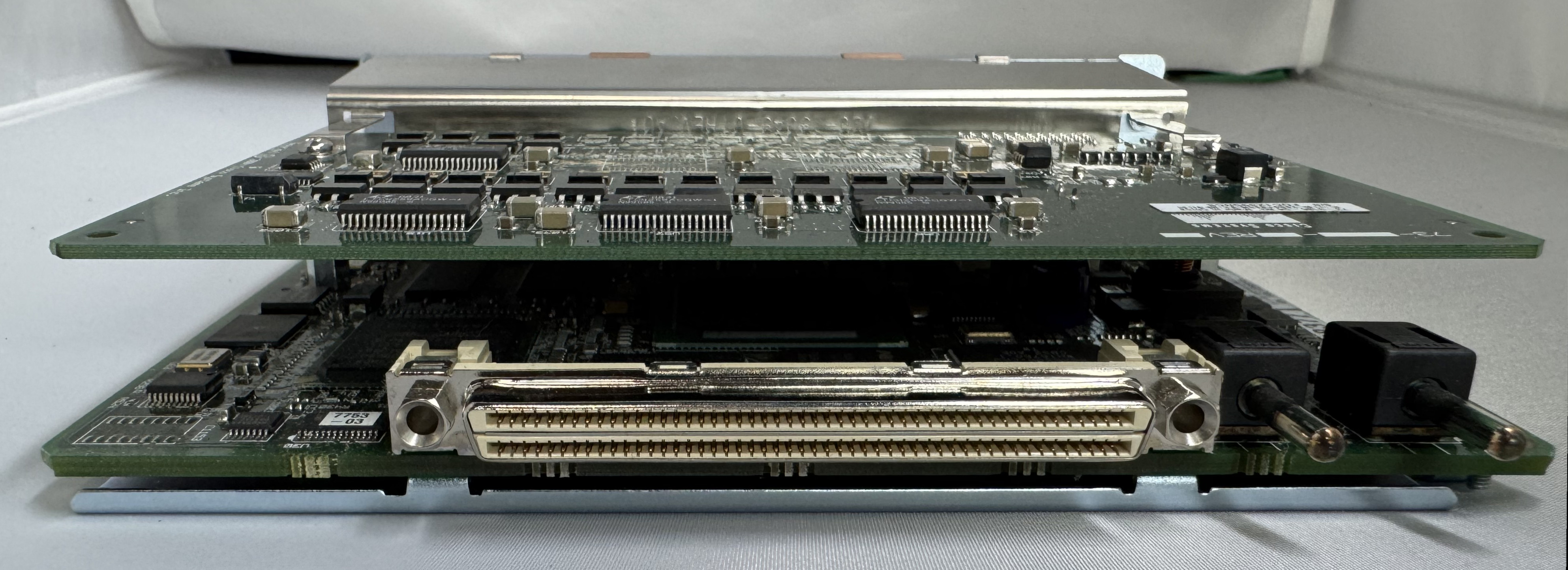
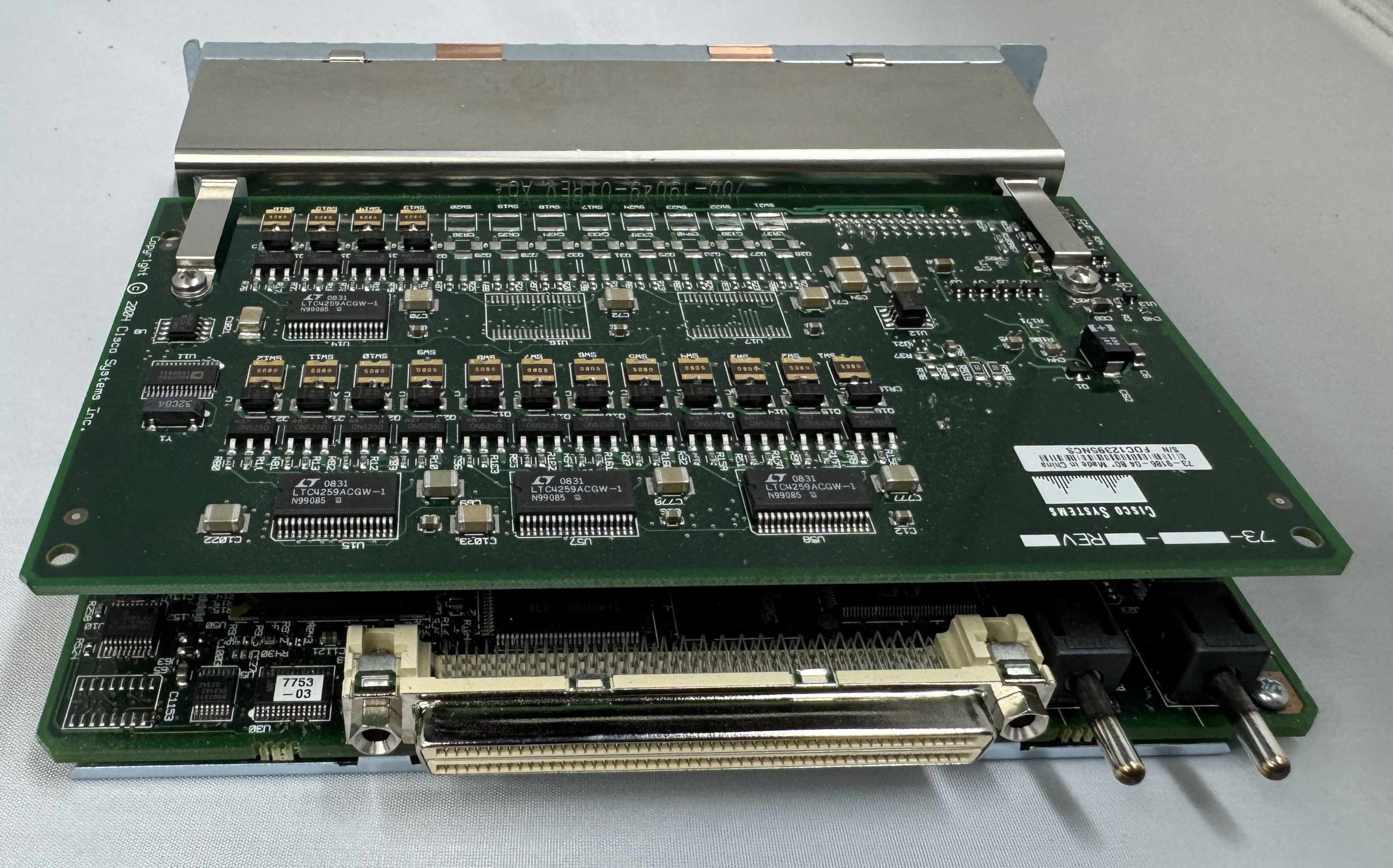
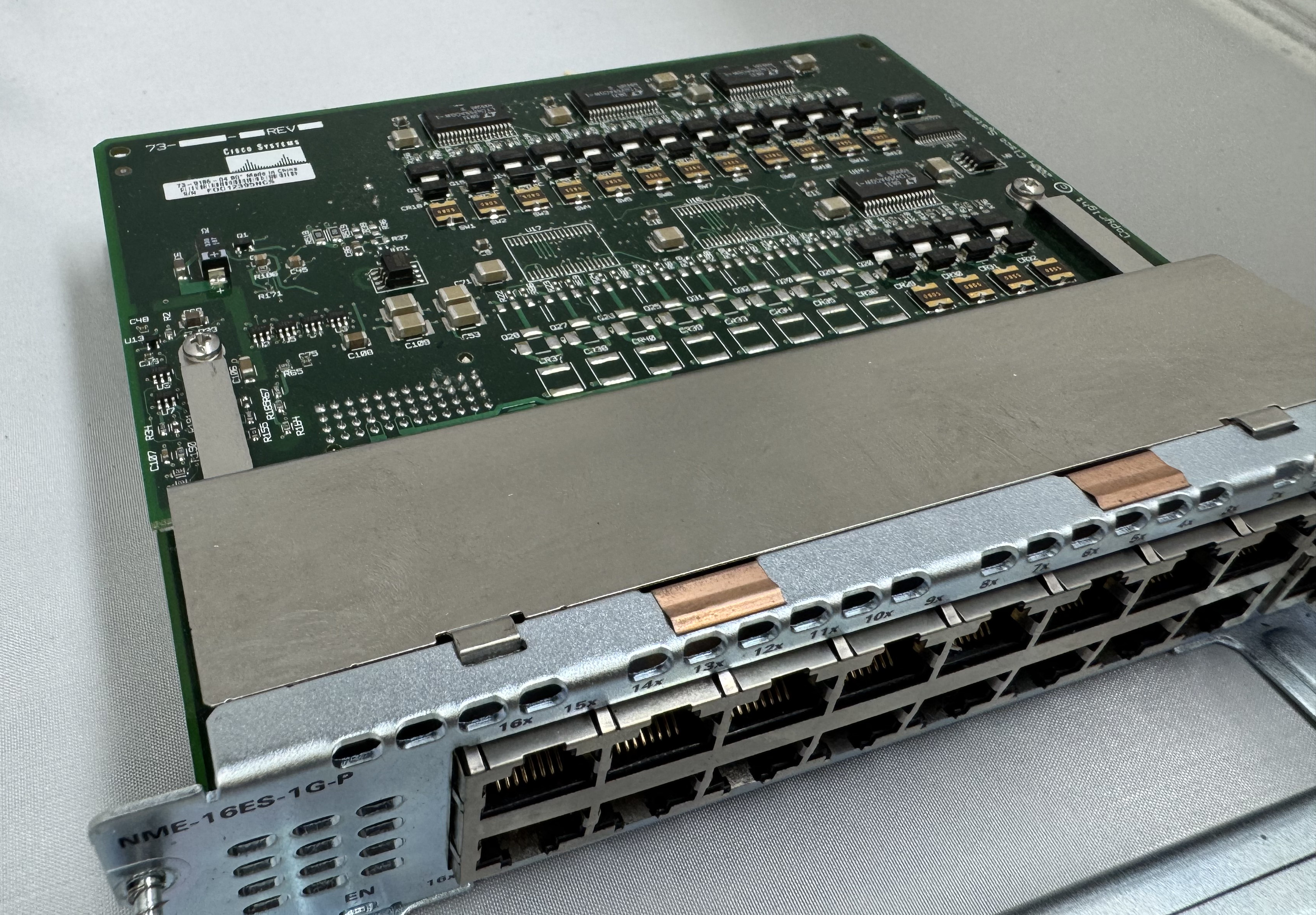
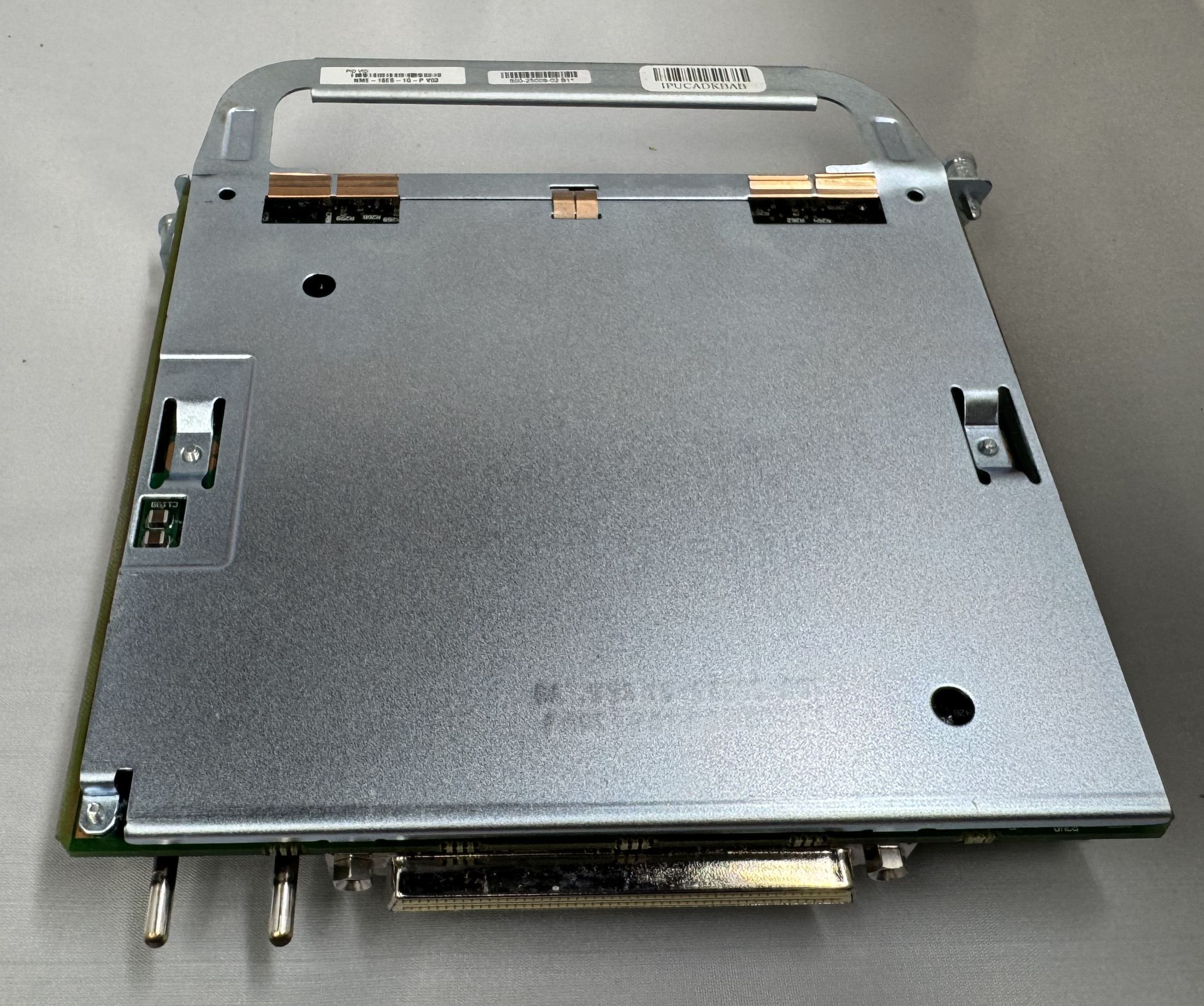
I bought a T1 card because I thought it would be fun to eventually play with. Then I bought a CISCO NME-16ES-1G-P. This is a Cisco Switch as a card module. They are odd. It runs its own OS. It has an internal port to the main system, then to configure any of the 16 x 10/100mb/s or 1 x 1gb/s ports you run ‘service-module gigabitEthernet 2/0 session’ and it opens a serial connection into the controller of this switch. It has a separate login, configuration, and IOS version. At first, I had to password bypass it because someone had left a password on it. I have used it some, but not much. It needs a firmware update. This is my main source of ethernet ports for devices.

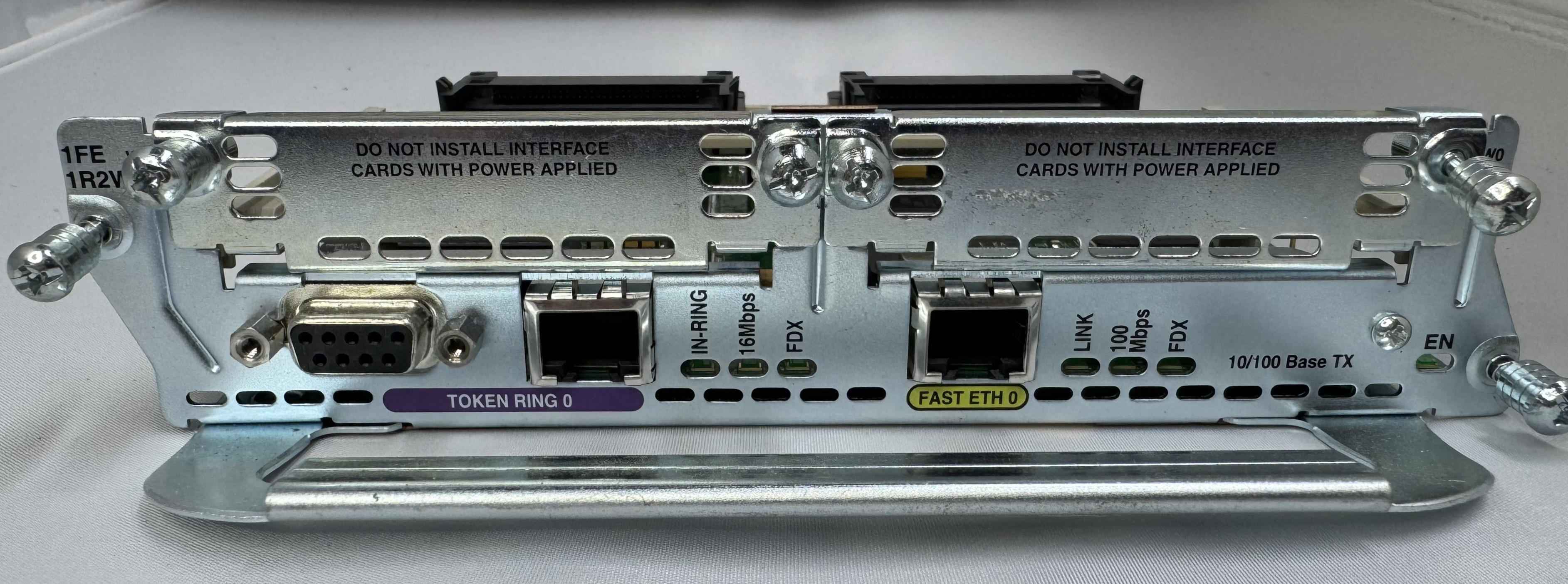
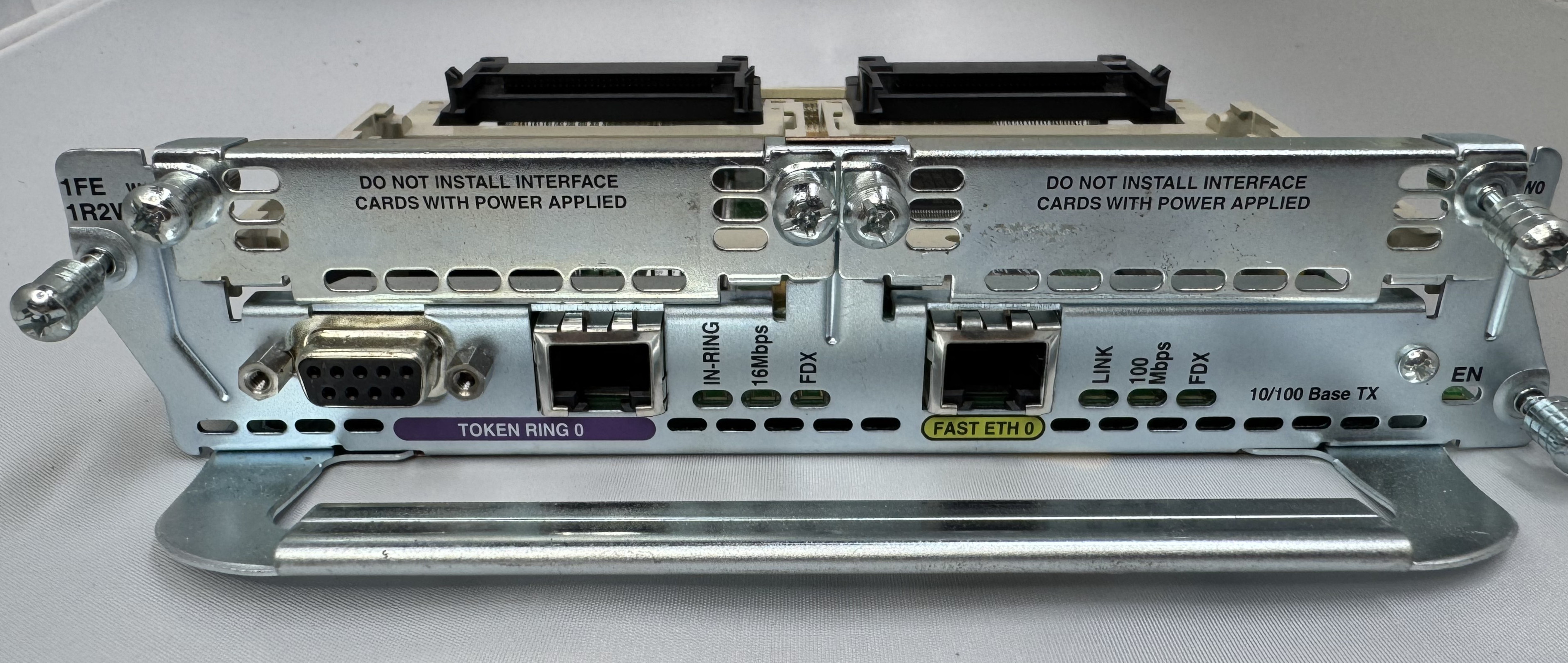
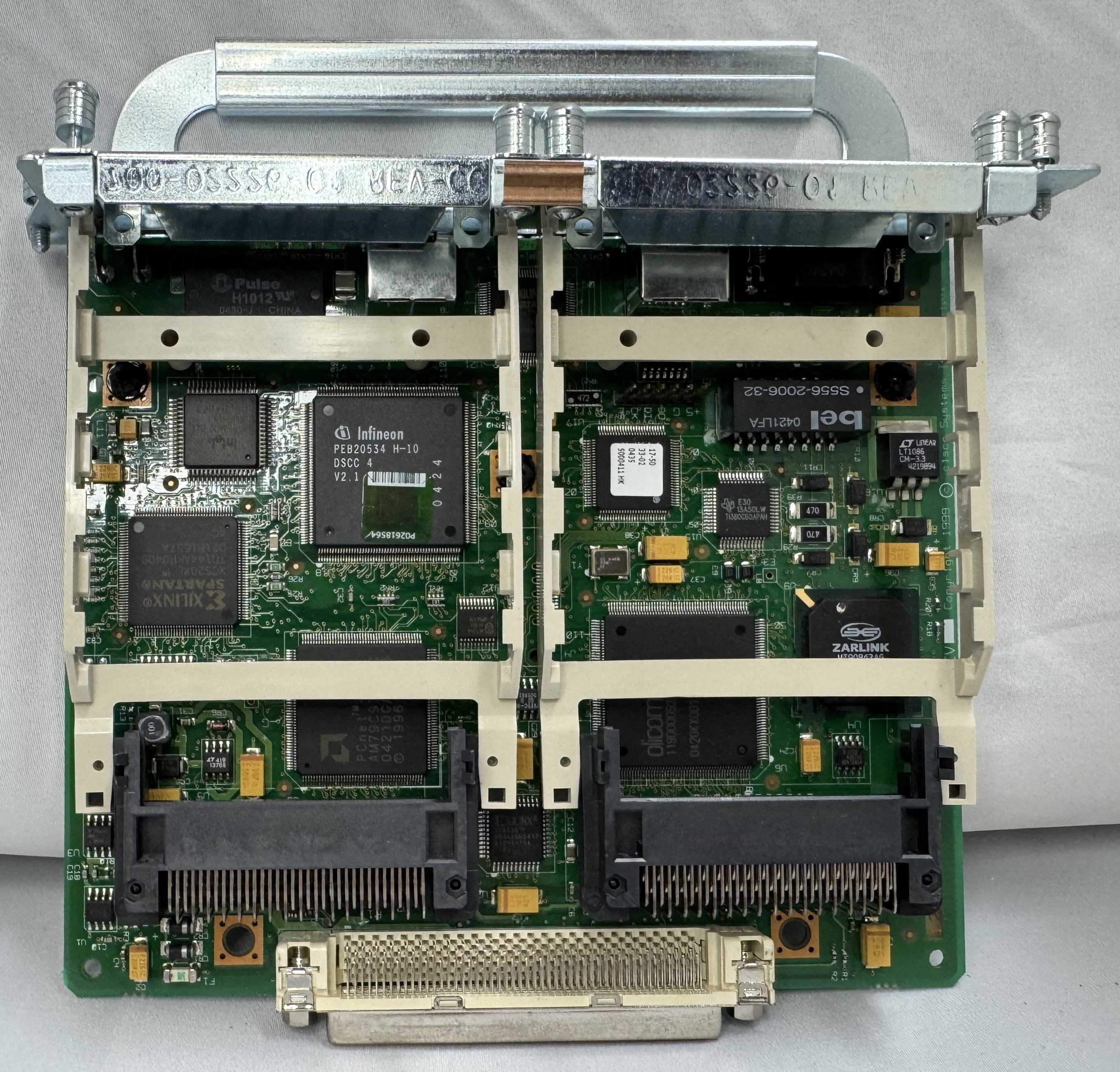
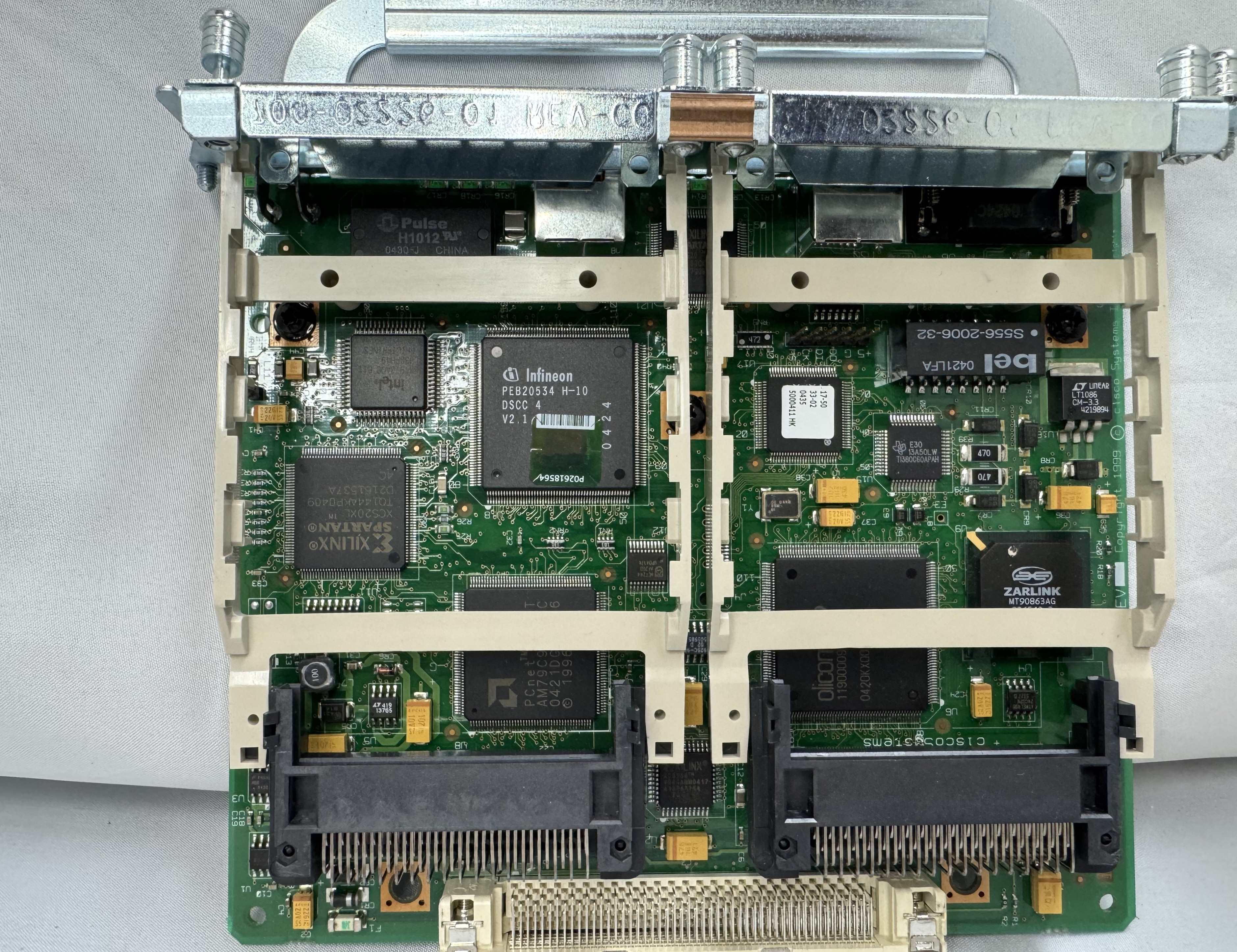
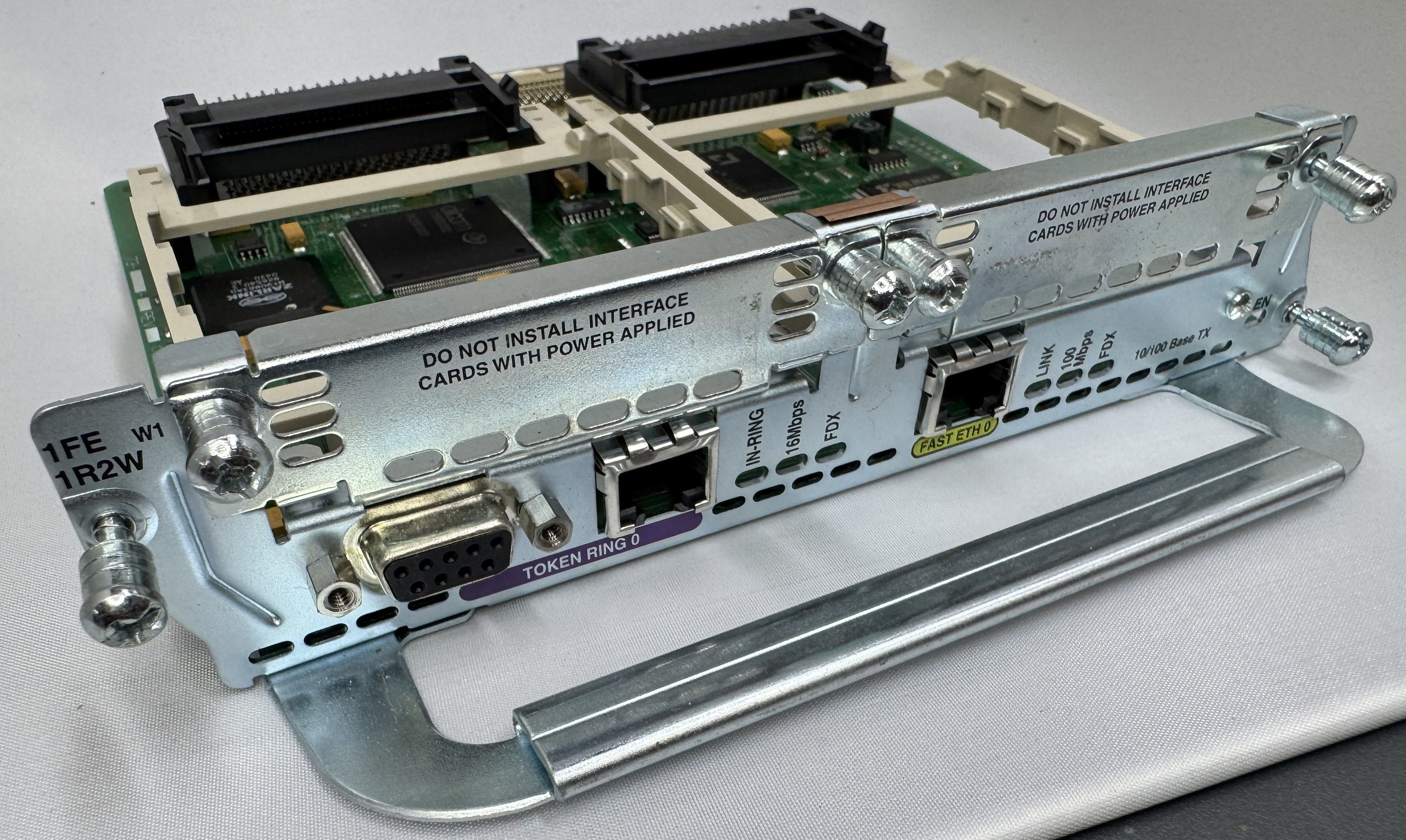
The last card I got is one of the main ones I wanted, a CISCO NM-1FE-1R-2W. This is a 1 FastEthernet (10/100), 1 Token Ring (DB9 or RJ45), and 2 WIC slots. I will do another post on Token Ring later.

Its worth mentioning, for the configuration and tests below, ports 0/0/0 – 3 are our 4FXS ports in HWIC slot 0. In HWIC1 slot (0/1/0 – 1) we have our dual modem card now, a WIC-2AM-v2.

Configuration

As mentioned, you do need a router with the Advanced Services image on it to do voice related features. Once that is loaded, and our hardware was in place, we started configuring the router to move voice data.

We need a pool of IPs that will be given out to clients as they dial in. To do this enter configuration mode and use:

ip local pool dialin-pool 192.168.9.10 192.168.9.20 recycle delay 3600 

You can tell from reading this blog that I have a way too complicated home network. I have the router itself on 192.168.7.0/24, then I made 192.168.9.0/24 for dial in addresses. To be able to send data to them and have them route on my core network, I have RIP running between my home firewall and this Cisco router. When I turn the router on, the routes pop up; when I stop using it for a while, the routes go away. You can set the start and stop of your pool to whatever you like.

dial-peer voice 3 pots 
 destination-pattern 3 
 port 0/0/3 

We need to say how the connection is handled once it comes in the modem. These connections are handled as “line” interfaces from there. We need to tell it this is a dial in line, what its max supported speed is (I just do the max, it will communicate less to the end modem), how flow control will work, and how auth will work.

The line configuration says it beeds ppp, since I do not specify the the auth system, any user is currently allowed… which is great!

line 0/1/0 
 modem Dialin 
 modem autoconfigure discovery 
 transport input all 
 autoselect ppp 
 stopbits 1 
 speed 115200 
 flowcontrol hardware 

Last, we need to configure the IP interface of this line, we do that by configuring the async line assigned to the modem port. This also is where we set which pool will be used for dial in users. I added the ppp timeout command because some of the older systems I have were taking a while to respond.

interface Async0/1/0 
 ip address 192.168.9.1 255.255.255.0 
 encapsulation ppp 
 peer default ip address pool dialin-pool
 async mode interactive 
 no keepalive 
 ppp timeout authentication 30

That is the key configuration needed to get dial up working! Below I will put my full config (minus password) in case any of it helps someone. Leave a comment if this helps you, or you need extra help!

Full Configuration

hostname router 
! 
boot-start-marker 
boot system flash:c3825-adventerprisek9-mz.151-4.M10.bin 
boot-end-marker 
! 
enable secret 0 test
! 
aaa new-model 
aaa authentication login default local line 
!
aaa session-id common 
no network-clock-participate slot 1 
dot11 syslog 
ip source-route 
ip cef 
! 
ip dhcp pool TOKEN 
 network 192.168.8.0 255.255.255.0 
 default-router 192.168.8.1 
 dns-server 192.168.7.1 
!
ip domain name lbt.home.ntbl.co 
no ipv6 cef 
!
multilink bundle-name authenticated 
voice-card 0 
crypto pki token default removal timeout 0 
username admin privilege 15 secret 0 admin
username test privilege 0 password 0 test 
!
redundancy 
!
ip ssh version 2 
!
interface GigabitEthernet0/0 
 ip address 192.168.7.10 255.255.255.0 
 duplex auto 
 speed auto 
 media-type rj45 
! 
interface GigabitEthernet0/1 
 no ip address 
 shutdown 
 duplex auto 
 speed auto 
 media-type rj45 
!
interface Serial0/3/0 
 no ip address 
 shutdown 
 clock rate 2000000 
! 
interface FastEthernet1/0 
 no ip address 
 shutdown 
 duplex auto 
 speed auto 
! 
interface TokenRing1/0 
 ip address 192.168.8.1 255.255.255.0 
 ring-speed 4 
! 
interface GigabitEthernet2/0 
 ip address 100.64.0.1 255.255.255.0 
!
interface Async0/1/0 
 ip address 192.168.9.1 255.255.255.0 
 encapsulation ppp 
 peer default ip address pool dialin-pool 
 async mode interactive 
 no keepalive 
 ppp timeout authentication 30 
!
interface Async0/1/1 
 no ip address 
 encapsulation slip 
! 
interface Async0/2/0 
 no ip address 
 encapsulation slip 
! 
interface Async1/0/0 
 no ip address 
 encapsulation slip 
! 
router rip
 network 100.0.0.0 
 network 192.168.7.0 
 network 192.168.9.0 
 neighbor 100.64.0.2 
 neighbor 192.168.7.1 
!
ip local pool dialin-pool 192.168.9.10 192.168.9.20 recycle delay 3600 
ip forward-protocol nd 
no ip http server 
no ip http secure-server 
! 
ip route 0.0.0.0 0.0.0.0 192.168.7.1 
!
control-plane
!
voice-port 0/0/0
!
voice-port 0/0/1
!
voice-port 0/0/2
! 
voice-port 0/0/3 
!
mgcp profile default 
! 
dial-peer voice 3 pots 
 destination-pattern 3 
 port 0/0/3 
!
telephony-service 
 max-conferences 12 gain -6 
 transfer-system full-consult 
!
line con 0 
line aux 0 
line 0/1/0 
 modem Dialin 
 modem autoconfigure discovery 
 transport input all 
 autoselect ppp 
 stopbits 1 
 speed 115200 
 flowcontrol hardware 
line 0/1/1 
 stopbits 1 
 speed 115200 
 flowcontrol hardware 
line 0/2/0 
 stopbits 1 
 speed 115200 
 flowcontrol hardware 
line 1/0/0 
 stopbits 1 
 speed 115200 
 flowcontrol hardware 
line 130 
 no activation-character 
 no exec 
 transport preferred none 
 transport input all 
 transport output lat pad telnet rlogin lapb-ta mop udptn v120 ssh 
line vty 0 4 
 transport input ssh 
!
scheduler allocate 20000 1000 
end 

Dell 316SX (Intel 386) Restoration

I recently got around to restoring a Dell 316SX—my first childhood computer. It’s a 386SX that lived in my parents’ attic for decades, and reviving it was a journey full of debugging, power supply replacing, and data recovery.

Early Memories

This computer was the first computer I had growing up: a Dell 316SX, with a Intel 386SX. I remember being little and playing Sesame Street games on Prodigy on a parallel port dial up modem (I need to see if I can find that). Shout out to the people trying to bring Prodigy back, https://www.vintagecomputing.com/index.php/archives/1063/bringing-prodigy-back-from-the-dead. There is a photo of my mother pregnant with me, playing the original Sim City on this computer. I always knew I had this computer in my parents attic, and one day I would need to get it out to play with it. Now that I have a bit more space to work on these projects, I got that system (and an old 486DX2 that someone gave me well past its prime) to play with.

More will come of the 486 on here, but that one got going pretty easily and is my go to machine since it has 5.25″ floppy, 3.5″ floppy, a CD-ROM drive, and its hard drive died so I gave it an SD card reader. That makes the 486 very useful; it also has a ton of ISA slots and is easy to work in.

I found a catalog with this computer in it! A PC World from 1990, page 27! I think the monitor is long gone, being a big heavy thing to store. I know my parents got it through a program at one of their work that discounted computers so people could work at home.

I am guessing this was the 40MB VGA Color Plus system. This one also has 4MB of ram, which would have been added on later.

Powering On

Anyway, back to the Dell 316SX. I could do the right thing and check all the capacitors and everything in the system; that’s what I should have done… So I turn the system on, and I get the familiar fan noise, and the 1990s smell. But no beep, no post, no nothing. The floppy drives don’t even attempt to seek. I left it for some time hoping that the capacitors would reform on their own, and come back. No luck.

I took the case off for the first time in 30 years or so, and it all looks in good condition. No rust or corrosion from anything leaking. Below are some nice photos of the board and the system. It is a Dell 316SX (no math co-processor) Motherboard revision B03. (I had some glare on the board, so I uploaded several photos)

My first thought after chatting with ChatGPT was that this system was old, and had a Dallas clock chip. The Dallas DS1287 is a real-time clock with built-in battery — a common failure point in old PCs because the internal battery can’t be replaced easily. The internet said some 386 systems will fail to post if this chip is completely dead. I order a replacement (https://www.ebay.com/itm/134217827379) from the same vendor I got the PS2 Serial adapter from. Wait a few days, it comes, pop it in AND… nothing…

At this point I figure we are probably looking at a power problem. This system is 35 or so years old, its big capacitors failing would not be a shock.

Power Supply Restoration

I don’t love dealing with power, but here we are. I got the multimeter out and started probing the connections I could see. This is an older power supply than anyone today is used to, this is following the original IBM AT standard, minus the fact that is a seemingly proprietary Dell header on the motherboard. For anyone with the same system, the connector is a MOLEX 09-50-8121, more on that later.

Reading the motherboard pins +12V, +5V looked good, -5V, and -12V looked a tiny bit low, but within tolerance for a system like this. I popped in a ISA/PCI diagnostic card and see that the RESET line is holding high, and the CPU is never being released. Then I probed the last line on the motherboard PSU connector, POWER GOOD; this pin goes high once the power supply has all the lines at a good voltage, releasing the processor to start… processing… That line never came up for me, and thus never released the processor. I opened the power supply and saw it was 2 boards with many wires going in-between them. I may eventually repair this power supply, but I do not feel like tackling that whole thing right now. I put that power supply on the shelf, and started the task at building a new one to meet this computers needs.

A while ago I bookmarked this device, https://www.tindie.com/products/dekunukem/picopsu-adaptor-for-ibm-5155-ibm-pc-compatibles/, an ISA card that can replace a power supply in these old machines. Looking at that I thought it would be a good place to start. I didn’t want to use this exact thing here, because the Dell 316SX only has 3 ISA slots, and I didn’t want to lose one to power. That brought me to 3D printing a bracket to hold whatever parts I needed for this power supply. The original power supply was a 85 watt, Astec SA85-3407.

The low wattage supply was neat because there are tiny modern supplies that can do 200ish watts. They are a bit scary because they are an exposed power supply delivering 200 watts. They also deliver ATX power, not the AT power I need. These days there are cables to convert between the two standards. Yet, again, the Dell used a specific MOLEX 09-50-8121 header, which I found on Mouser for $0.92. I gathered up my adapter cable, and the new header, and a cable kit from Amazon for Molex connectors; and spent the evening rewiring a new header, very slowly and carefully. I checked every pin several times to not spell doom for the system.

Its also interesting to point out, with the PicoPSU, it takes 12V DC in. This helps it be smaller and cooler, since the AC-DC conversion is done with a brick outside the chassis.

Then I plugged in just the motherboard, and with the power supply held in a little soldering clip, hit the power. And the system came up! Well at least I got video with the BIOS showing up! Plugging in the diagnostic card I saw +12V, -12V, +5V were all good, but the card said 3.3V was failing. That’s odd, 3.3V is not a voltage I provide. Turns out the motherboard uses the -5V rail to create the 3.3V rail. Searching online shown that -5V wasn’t really needed for anything, but its part of the ISA spec and some Sound Blasters and network cards need it, which means I wanted to have it. It’s worth noting this rail is used in very little quantities, the original power supply had .30A for the -5V line max. While the ATX standard mentions -5V, its not longer used in modern PCs. Thus, no modern power supply tends to give out the -5V. I got a step down converter that can do negative voltages and stepped -12V to -5V. Wired that in line, and I suddenly had all the power rails I needed!

Now that we had our semi-sketchy power situation working, I wanted to design a bracket to drop in where the old power supply went and could hold all these pieces nicely in place. I ended up working on a cover to mostly protect myself from the open PicoPSU running at the heart of the system. I added a fan with a speed controller as well, since the original power supply fan in the system was the only airflow the whole computer has. Then I added another fan to the front of the chassis. The system originally only had the one power supply fan, and when I took thermal measurements some of the chips were getting toasty and I thought another fan couldn’t hurt.

One last fun fact about this old power situation. The old computers didn’t have “soft power” like we do today; where you hit on and it tells the BIOS to start booting. This system had a big ON/OFF switch in the front with mains voltage (120V for the US) going to it. In replacing the PSU, I swapped this for a ATX, low voltage on, switch.

Video

While the Dell 316SX does have standard VGA on the back, there is not a spot for pin 7; the second pin in the second row. If you lookup pinouts for VGA online, this pin is either called “green ground” or “not used”. These days even if not used we include a spot or pin for it and not connect it. This machine has no spot for a pin. I had to get a VGA cable, and cut the pin out; allowing the cable to plug in.

Data Recovery

Now we had power, and can POST. The Dell 316SX had a Seagate ST-157A-1 – 44MB IDE/ATA-1 HDD; and a Hardcard II XL – 100MB ISA card. The first thing I wanted to do was get a backup of each of these storage devices just in case after 35 years they suddenly died. The Hardcard was easy, I moved it over to the 486 I had, used an old copy of Norton Ghost, and captured the drive no issues.

The hard drive was a bit harder since the 486 is old enough it can only have 1 drive on its primary IDE channel; that left the secondary channel. In trying different setups I realized that the Dell 316SX did not have the correct hard drive parameters entered when it was in use. This means, when I tried to read it on a machine where I couldn’t set those settings, I wouldn’t get the correct data back. I HAD to have the disk read from the primary 486 IDE channel where I could edit the parameters to be incorrect on the 486 like it was on the 386. I got an ADAPTEC AHA-1542CP ISA SCSI CONTROLLER (from this seller), this allowed be to boot a DOS floppy, load Ghost, and image the drive to the new SCSI device, with the correct – incorrect hard drive parameters. This SCSI card has a full BIOS on it, allowing DOS to reference and even boot off of it without a driver.

The true savior here was Spinrite. I didn’t realize the hard drive parameters were causing my issues, and I thought the drive had just died. I figured I would give one last shot with Spinrite before calling the drive dead, and the data lost. Before I could start a scan, Spinrite popped up saying that the drive wasn’t recorded correctly and I should edit those settings!

After capturing images of both devices, I started cleaning the system, taking some photos, and putting it back together. One last test of powering it up, and the Hardcard died. It would no longer POST, freezing when the card tried to spin up. I am very glad I captured an image while I could! I copied that image into an image for the BlueSCSI device I had, and we were back in business! The Hardcard started giving “1703(K) — Hardcard IIXL Error at BIOS address C8000h.” which the internet said was the drive had died.

For those of us who haven’t done that much with MS-DOS in years, here is a reminder how partitions work (this is important because the old system had the Seagate drive as C and E, then the Hardcard as D); all Primary partitions that are accessible to the BIOS are added as the system boots, THEN all extended/logical partitions. This means, with the internal drive coming up as C: D:, then the Hardcard as E: I had to figure out how to switch them. In the end, it ended up being that the Hardcard was coming up as a extended partition, and it needed to be a primary one to force it earlier in the order. Turns out the Seagate drive had 1 primary, and one extended partition. After doing that change, and copying all the data back the system and all the links within Windows 3.1 came up correctly.

Cards

I got the Dell 316SX with a Hardcard II XL – 100MB ISA card and a Sound Blaster 16. I put some deoxit into the volume control knob of the Sound Blaster, it had the crackles when you moved it. That cleared it up.

I mentioned swapping the Hardcard for a SCSI controller. While I was in the system I also decided to get a 10MB Ethernet controller off ebay and put that into the system to have easier file transfers in the future.

Drives

This Dell 316SX has a 5.25″ drive bay, and a 3.5″ bay. Both are working happily, but I did give them some lubricating grease on their rails after cleaning them up.

Case Cleanup

I put some time into cleaning the case. For being ~35 years old, it was looking in good condition.

Conclusion

In the end, I am very excited to have my childhood Dell 316SX back up and happily running. It took some work, with non-stop issues along the way; but in the end, its working with most of its original hardware. Below are some other photos I have taken. While I was working on the system I ordered 4 more 1MB SIMMs to bring the total memory to 8MB. I figured I would max it out while I had the system open. The only downside is the POST checks all the memory and this slows it down a bit.

I uploaded this playlist of a few videos I took working on the computer; they are in a playlist below.

PS/2 to RS-232 Serial Mouse Converter

As part of my LAN Before Time rack project, I’m setting up classic PCs with a VGA and PS/2 KVM to manage them. However, one of my systems—a 486—lacks a PS/2 port for the mouse. A simple PS/2-to-serial adapter wasn’t enough; it required a proper signal conversion to work.

After some searching, I found this adapter kit on eBay: PS/2 to Serial Mouse Adapter. It’s based on an open-source project: necroware/ps2-serial-mouse-adapter. The kit didn’t include instructions, and the project assumes you already know how to assemble it; I decided to document my build process step by step.

A Quick Note on KVM Compatibility

This adapter worked flawlessly when I plugged a PS/2 HP Laser Mouse directly into the 486. However, when connected through my KVM, it worked for a few seconds before stopping. After some digging, I found a pull request from last year that mentioned a KVM fix. Flashing that updated firmware completely resolved my issue! Unfortunately, the main repository hasn’t been updated in two years, so hopefully, it gets some attention.

What’s Next?

Below, I’ll walk through assembling the adapter. After that, I’ll cover how to flash the updated firmware using a USB-to-TTL converter. These converters are cheap and easy to find—here’s the one I used: USB to TTL Adapter. Finally, I will show a case I designed and 3D printed for the device.

Steps

  • Put the serial connector through the top side of the board and solder it in place on the bottom, starting with the mounting legs and using plenty of solder. These take a lot of the strain of the connections. Then carefully do each of the data pins, making sure not to bridge any.
  • Insert the lower chip socket, and solder in place on the underside.
  • The Arduino Pro has 3 different parts we need to solder. The first is the head with the 90 degree pins at the end. This will allow us later to flash the controller if we want to move to other firmware. Put those through the top (the side with the chip) and then solder them in the underside.
  • Next, put the Arduino header pins in the bottom. I put them into the header connector to hold them in place. Do not put too much heat on each pin with the plastic part below. (Not my best soldering job)
  • Solder in the 10k resister, here I am soldering it on the bottom while it went in through the top. After it is in, cut of the excess legs.
  • Solder in the PS/2 port, use a good amount of solder on the mounting points so it doesn’t move when inserted, then solder the data pins.
  • Solder in the micro-usb port, careful of the tiny pins.
  • Add the jumper pins, solder them in.
  • Now time for the capacitors, these are polarized, note the right side of the silk screen is white that should line up with the white side of the cap. (the shorter leg side)
  • Finish up by soldering all the pin headers for the controller to sit on the board.

The board should now be complete! If you bought it from the seller I did, (who has been great, and I have bought other items from) then you have the main repos firmware on it. I won’t go too far in depth for this, but if you clone the fork down you can then use Platform.IO to flash the firmware. There are guides out there to do this on. Platform.IO is great when doing Arduino projects.

If you go the same kit I did, then it comes with a “pro16MHzatmega168” not the “pro16MHzatmega328” used in the Pull Request. Change the two lines where the 328 is mentioned to the 168-model string. If you do not, you will get a “timeout connecting to Arduino” when attempting to flash.

As mentioned, you need a TTL converter, then to flash the chip. The TTL converter (which I hadn’t used before) pins actually line up with the pins on the Arduino Pro. You need to hold it there for a total of 30 seconds while it flashes. You can just stick the header pins of the Arduino through the holes of the converter, then hit send via Platform.IO.

Flashing the new firmware on my messy desk, I did not need long cables like this…

3D Printed Case

This is a device I will keep behind my old PC, and I didn’t want it to be a raw circuit board. I didn’t see any cases to 3D print, so I put one together. This was the first time I made a case that used little feet to snap the top and bottom half together; no screws! I also put little towers in to hold down the PCB in place. It took a few revisions, but I think came out nicely. There is also a little window to hit the reset button if needed. The black case was the second revision, the white case is the first.

Model: https://thangs.com/mythangs/file/1301661