Retro Computers

Restoring a Dolch Pac 65: The Last of the Luggables

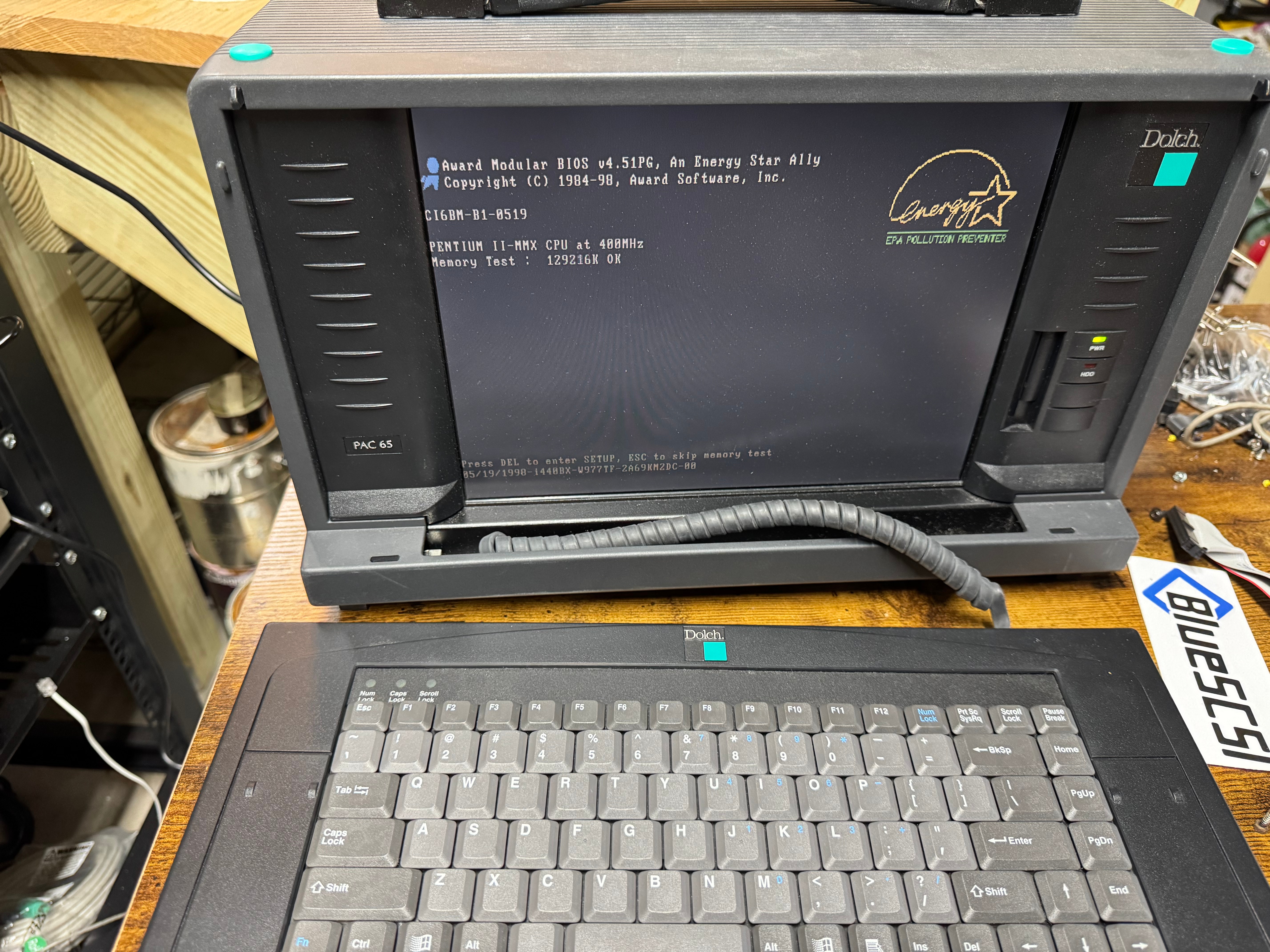
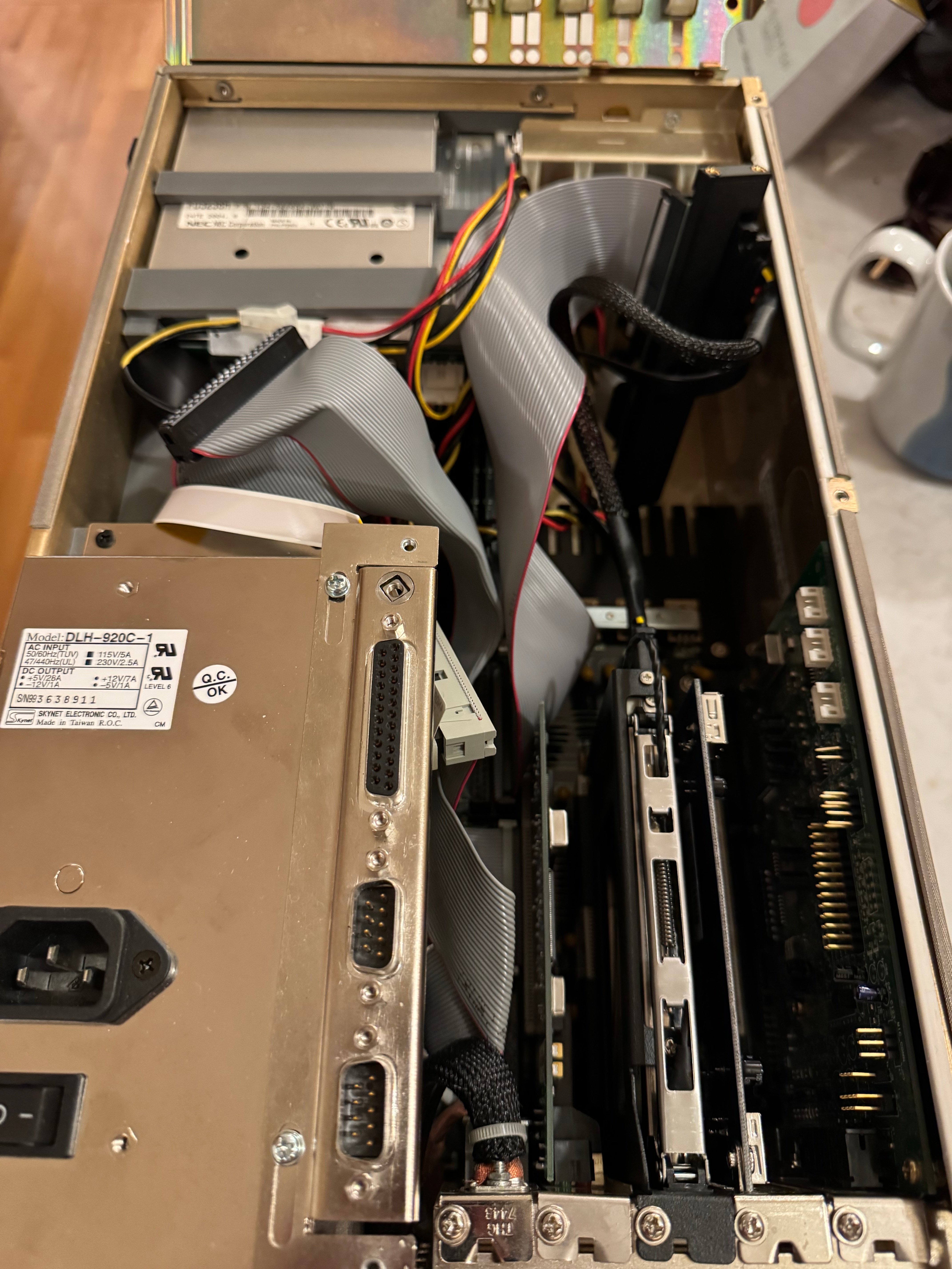
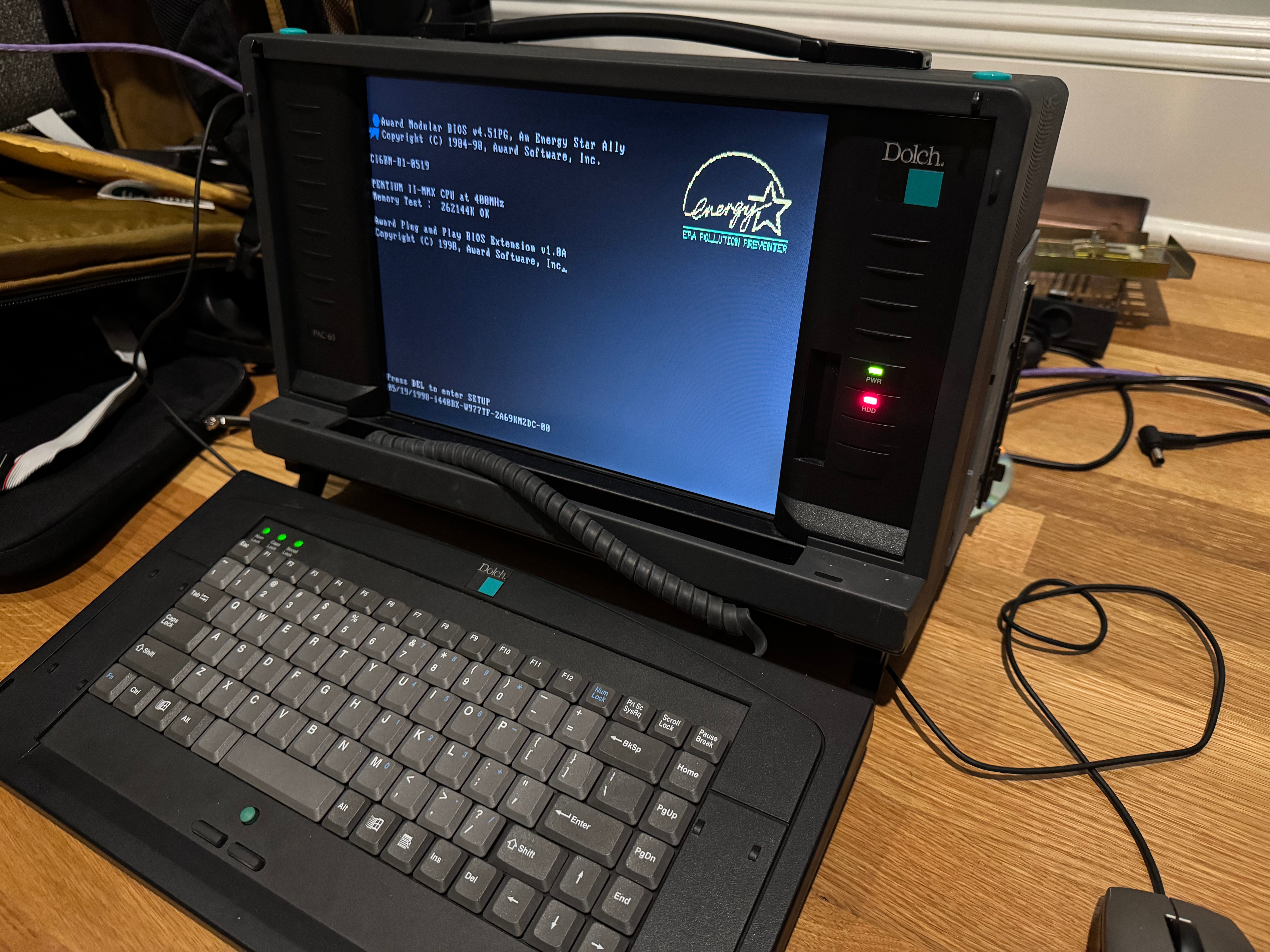
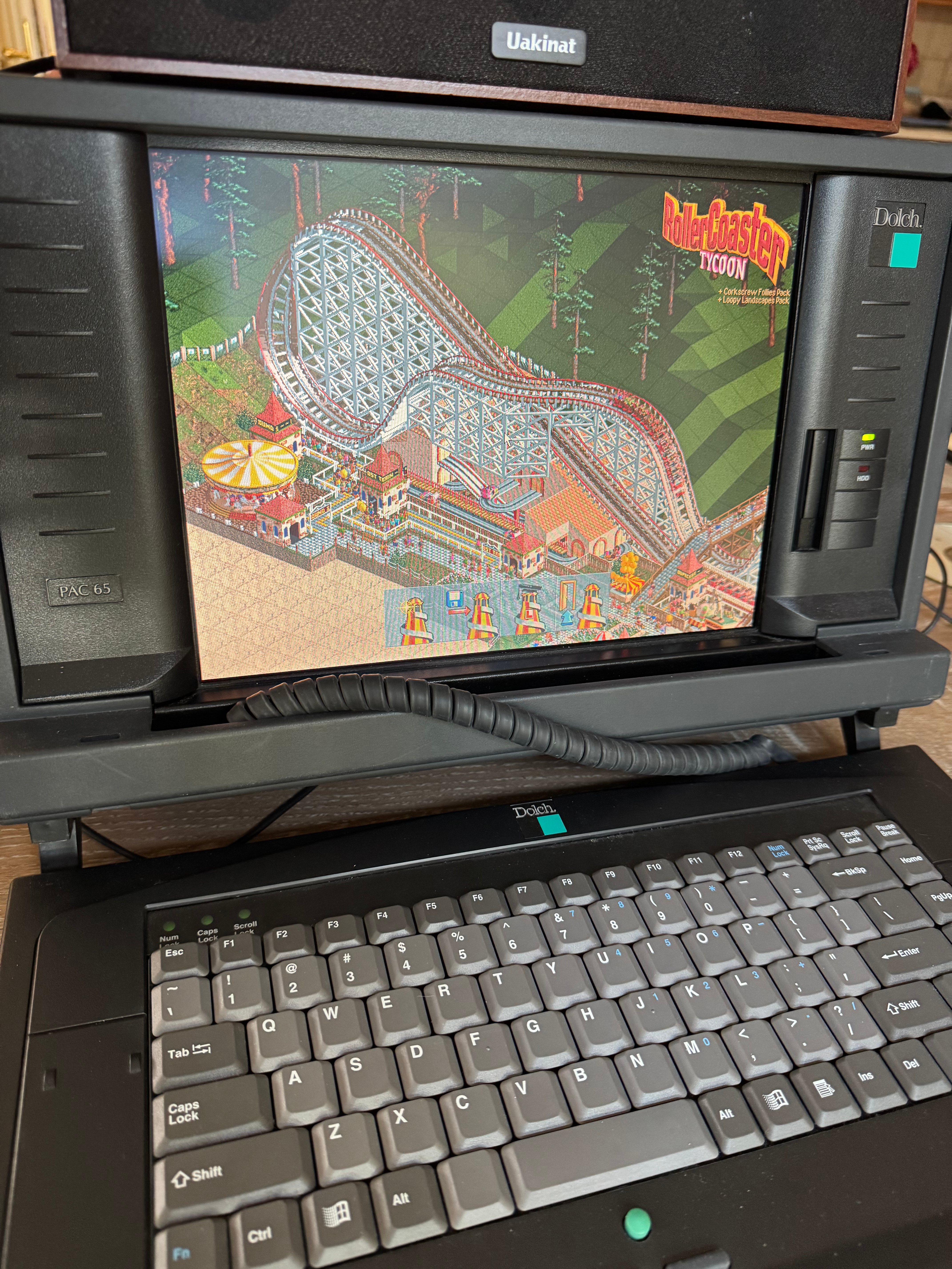
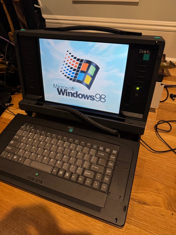
I love old portable computers. It goes back to the Compaq Portable II I have. I saw online there was a much later system from a company I hadn’t heard of called Dolch. The Dolch Pac 65, considered one of the last “luggable” computers. An industrial motherboard, with an ISA slot, four PCI slots, and a Pentium II 400MHz with MMX. These machines were built to be “portable workstations” for industrial use: factory floors, military, network diagnostics. A far cry from the Intel 286 in the Compaq Portable II. It also has an LCD screen instead of the small CRT of the Compaq. Gone are the days of tiny green and black displays, even if I love them. In comes a full 1024×768 LCD. I have been expanding my retro computing rack and wanted something more in the Windows 95 or 98 era. This system fit the bill.

Whenever I tried to find one online, they would come up for around $500. I saw one come up for around $150, with the small catch that it was in an “unknown” state and missing some of the panels and mounting brackets. I could see from one side photo that it had the power supply, and I saw what looked like the motherboard inside. A yolo later (and a few days), I had the system.

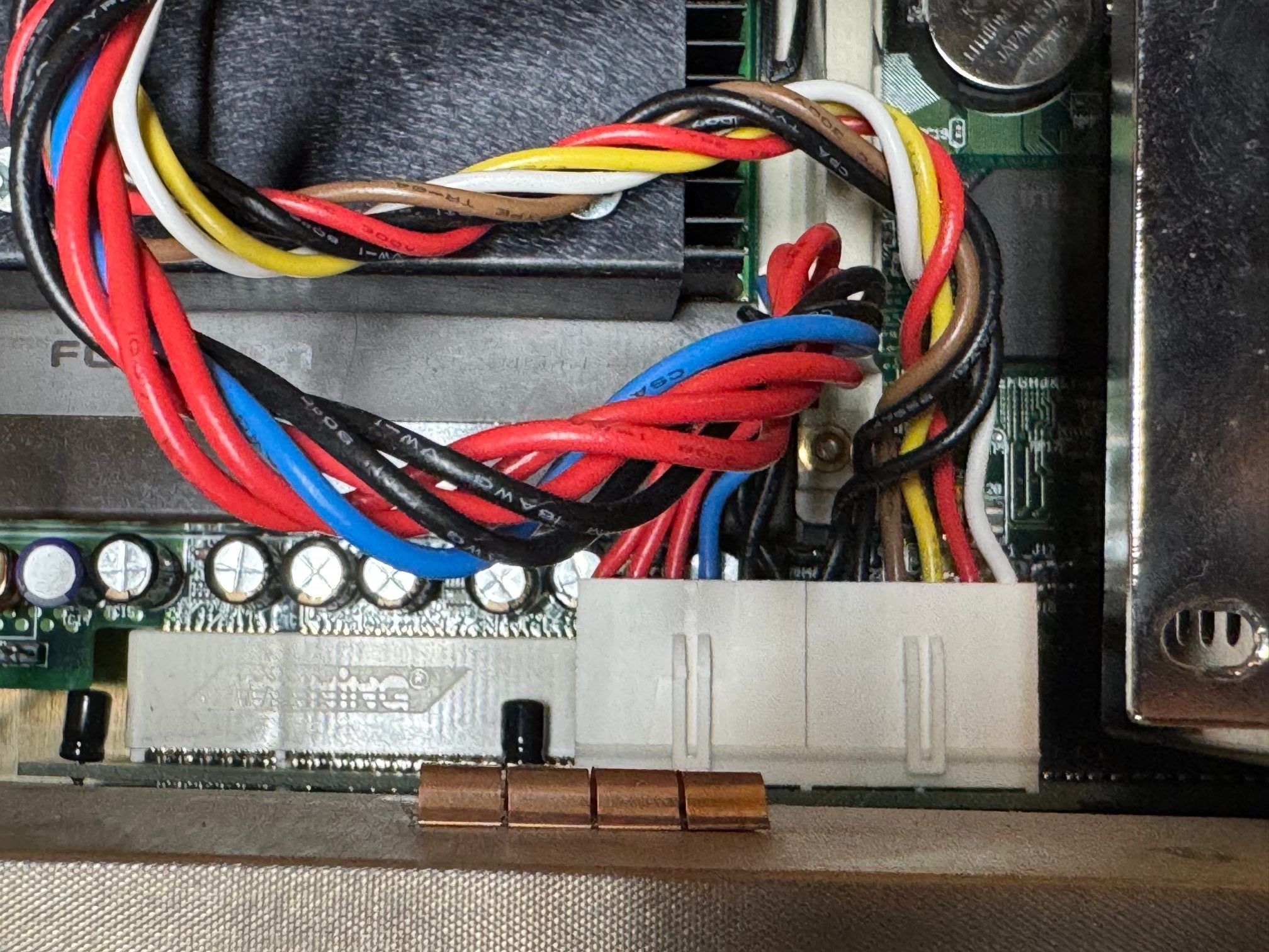
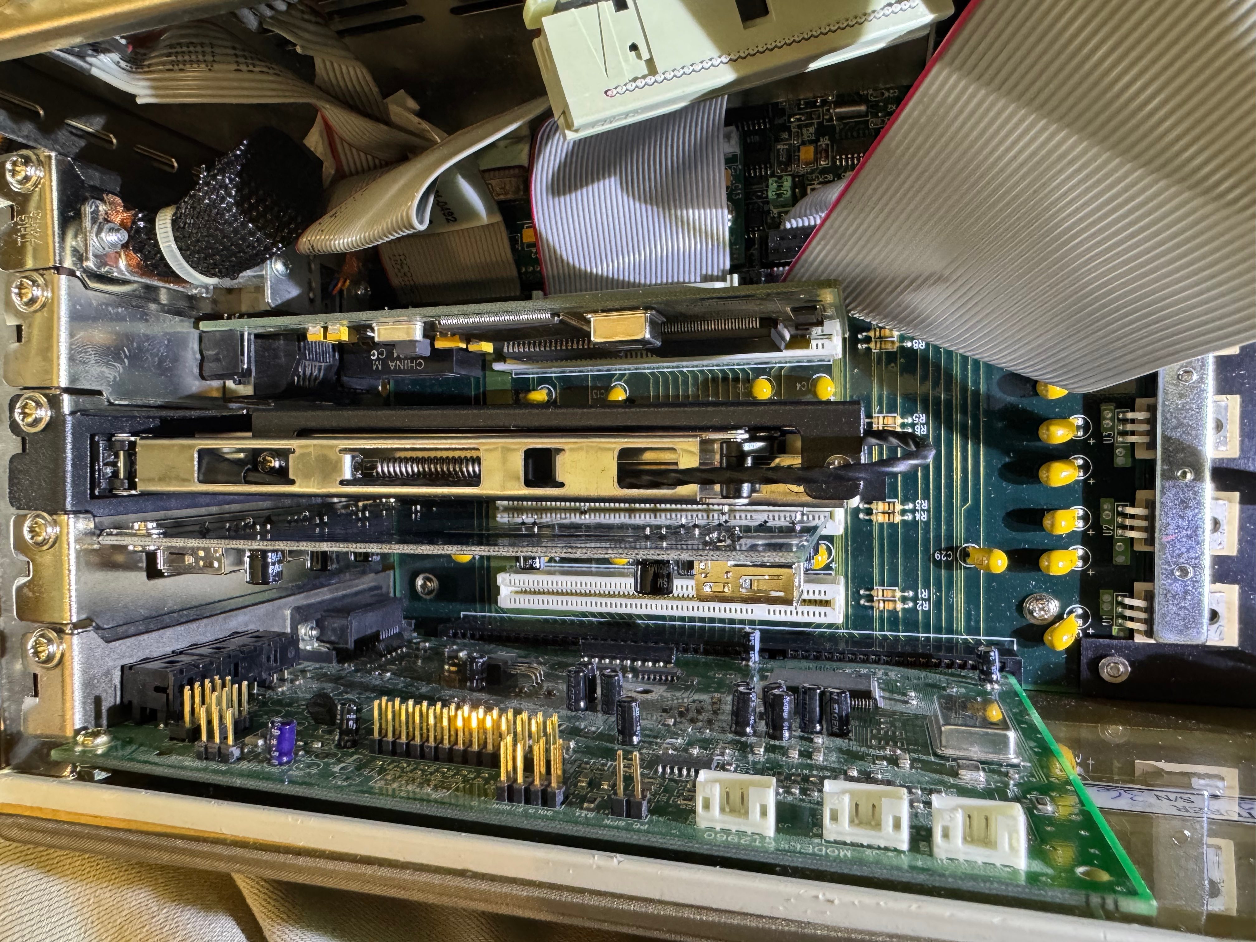
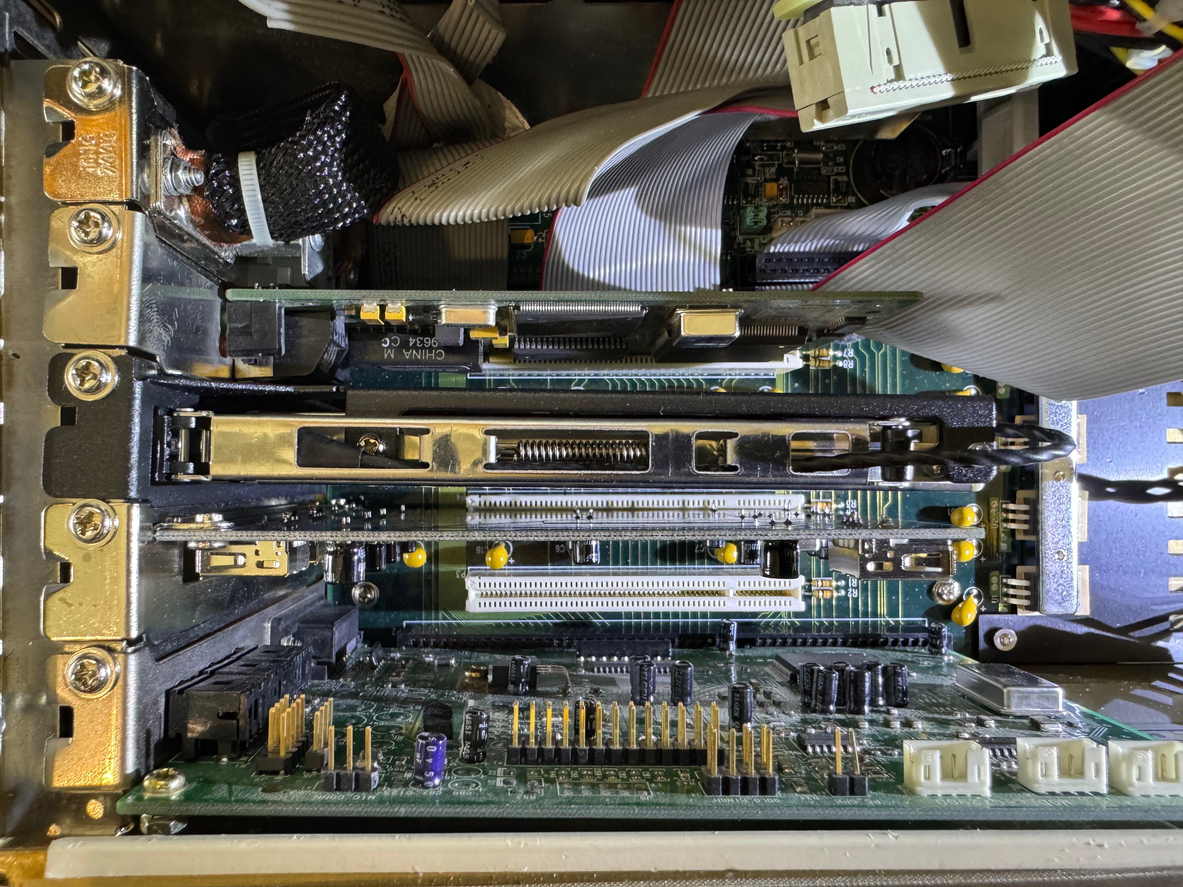
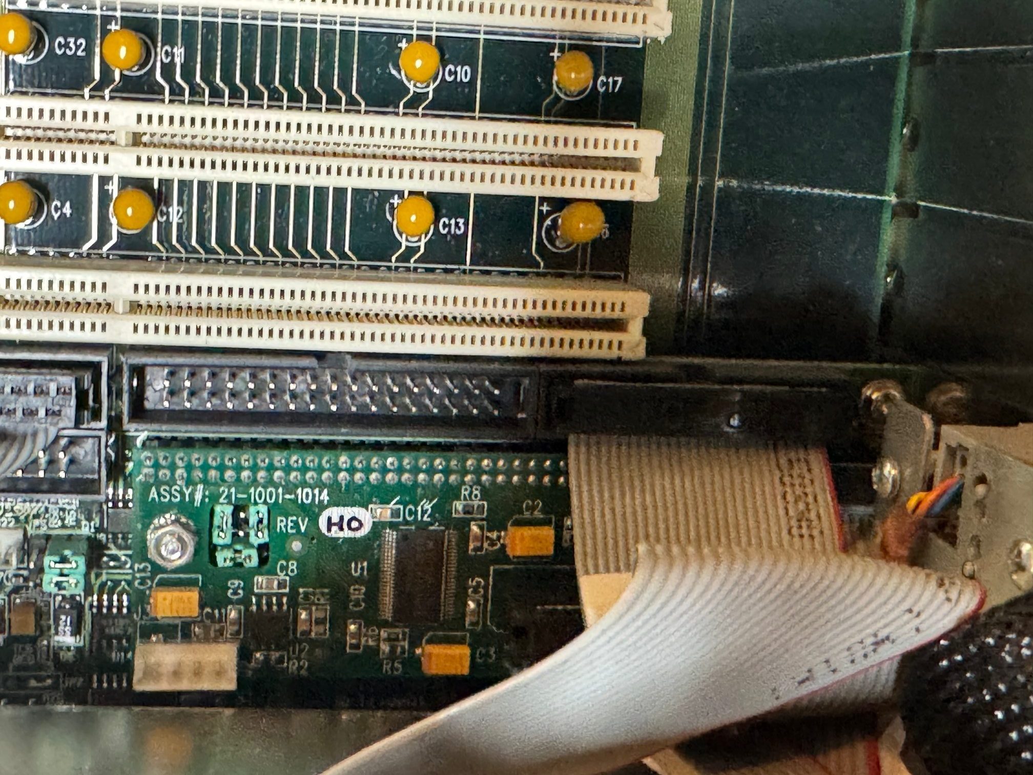
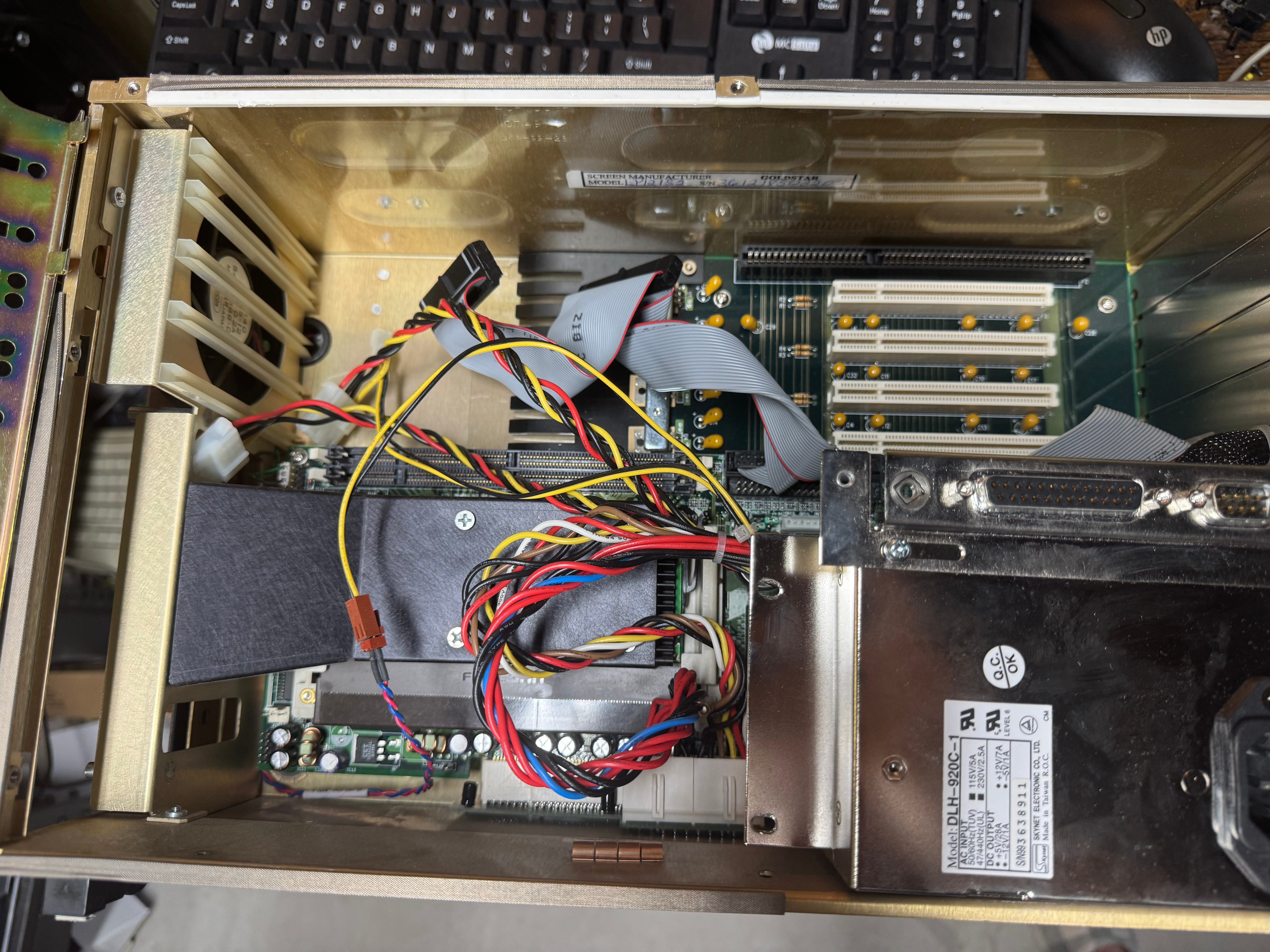
I was right! The motherboard was there! It had no disk drives, no RAM, no hard drive; it was perfect. A blank slate. The system definitely has some oddities. The motherboard is more of an industrial system, all on one board with CPU, memory, disk controller, ethernet, video card all together. Then a connector to another board that holds the ISA and PCI slots. My guess is it’s a PICMG or similar system. Being from that era, and a more industrial system, the fan is a 120-volt fan that always runs at a relatively high speed. I haven’t replaced it yet, but that may be on the shorter list of parts to swap out for a good quality of life improvement.

I need to thank Curious Marc! He also has this system, documented it well, and collected/uploaded all the drivers! This made getting the system online a good amount easier. He also has tables about the different RAM types it supports and information about the motherboard that got me moving a lot quicker on this project.

The first step was to get some memory to prove the system could POST. I found the system could use PC100 SDRAM, up to 256MB a stick for buffered RAM (128MB for un-buffered)! The KTD-WS610R/256 Kingston RAM ($7.50) I got was very interesting, it’s a multi-PCB board, joined together. I ordered just one for now, 256MB is plenty for this machine. I am currently using one of the two DIMM slots the machine has.
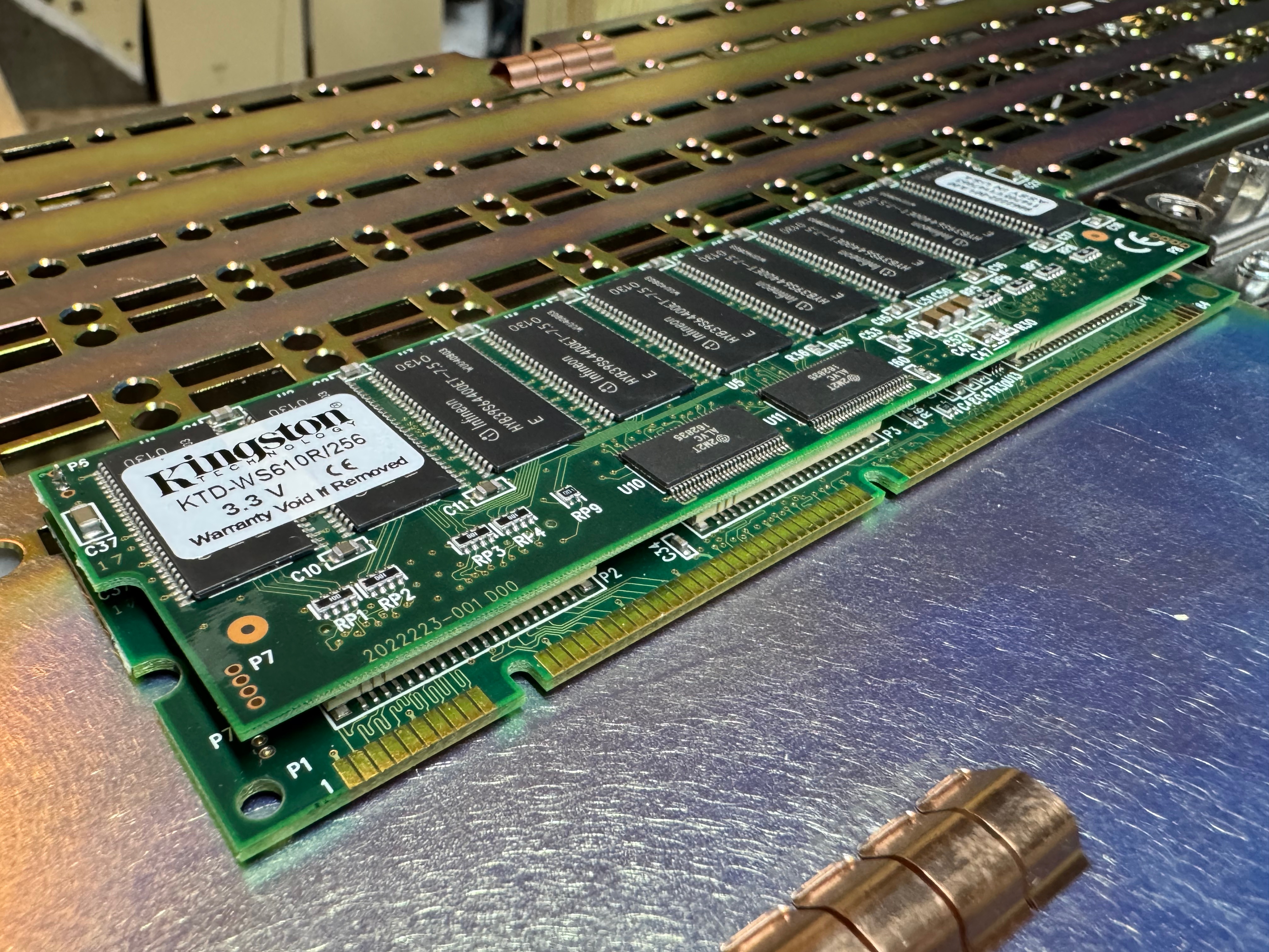
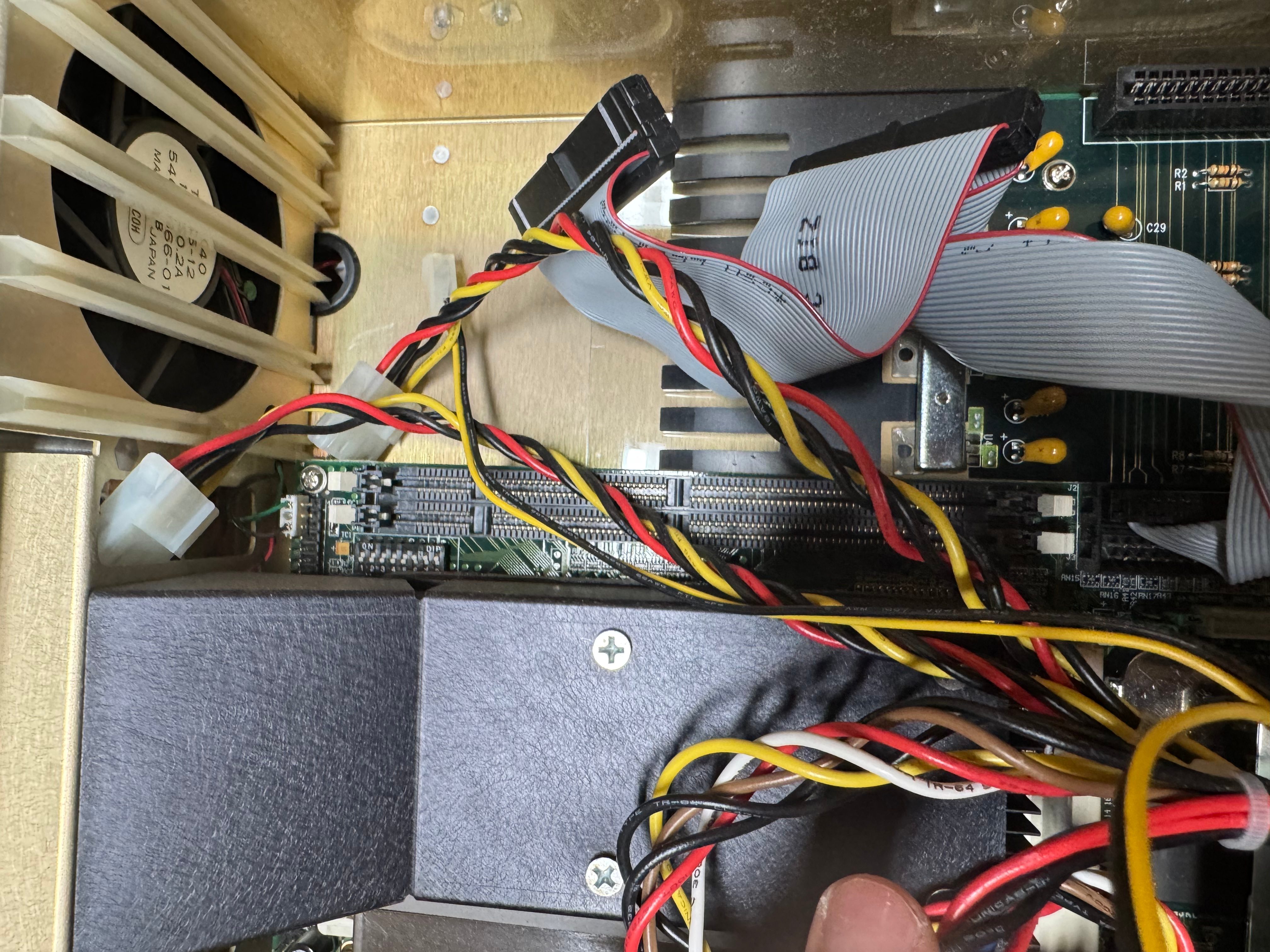
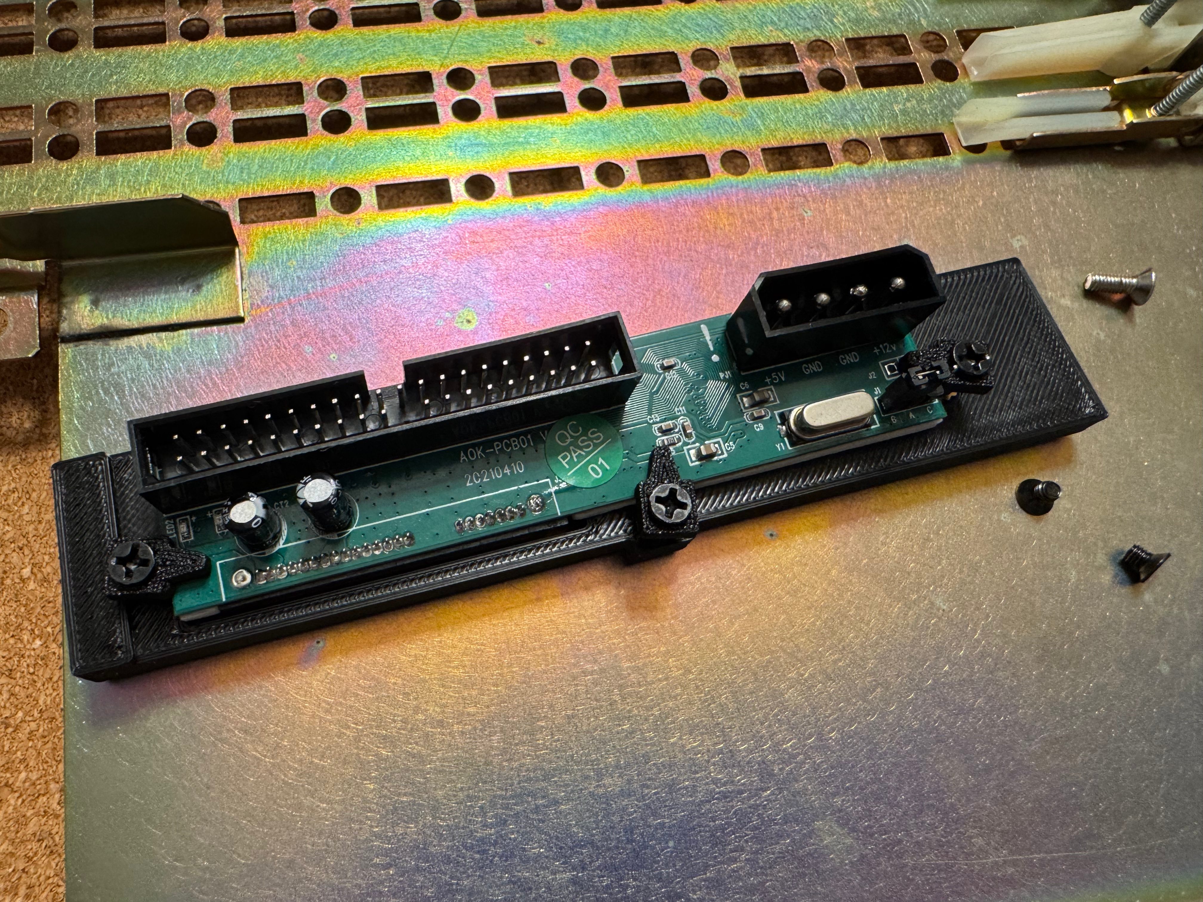
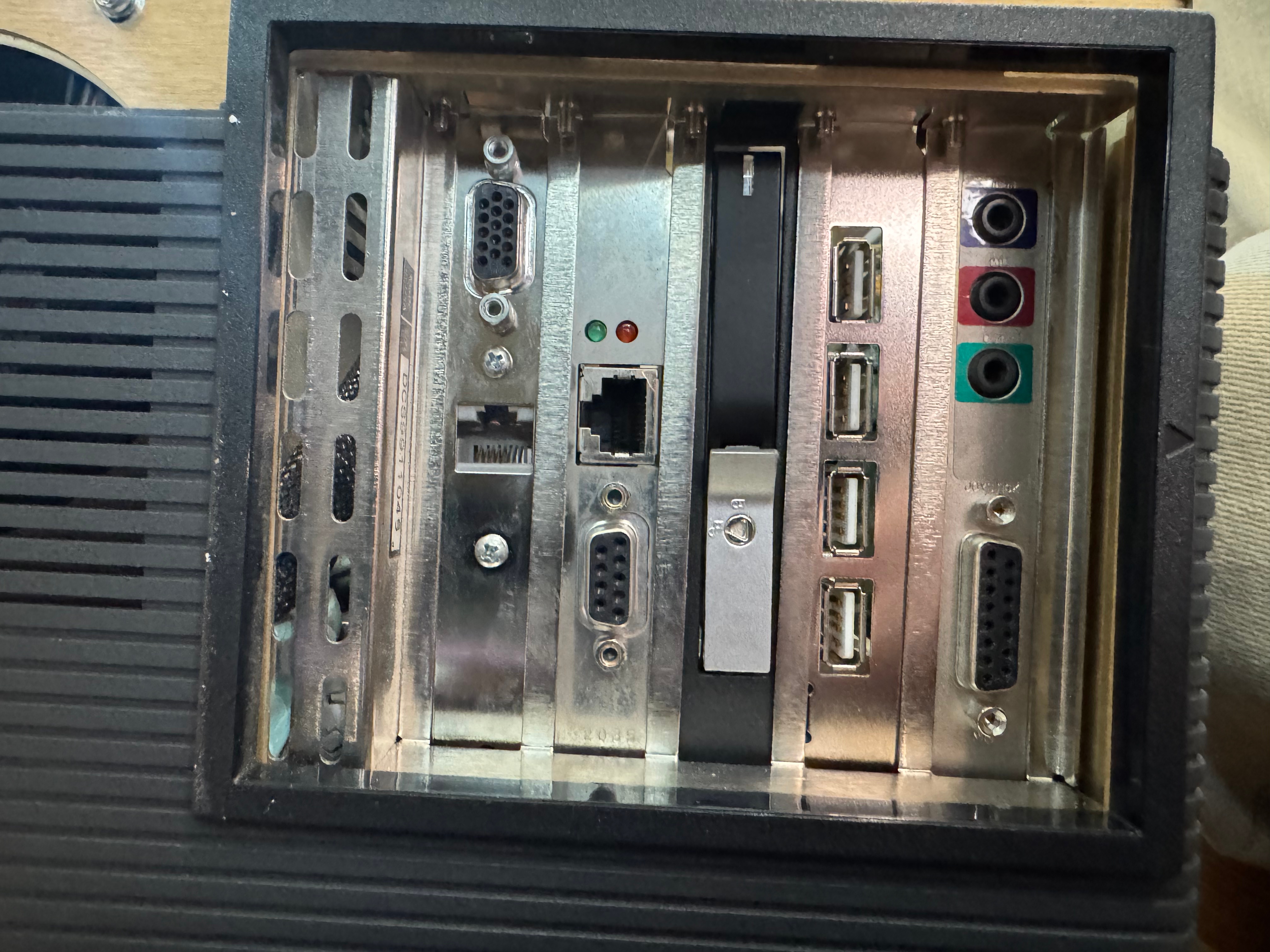
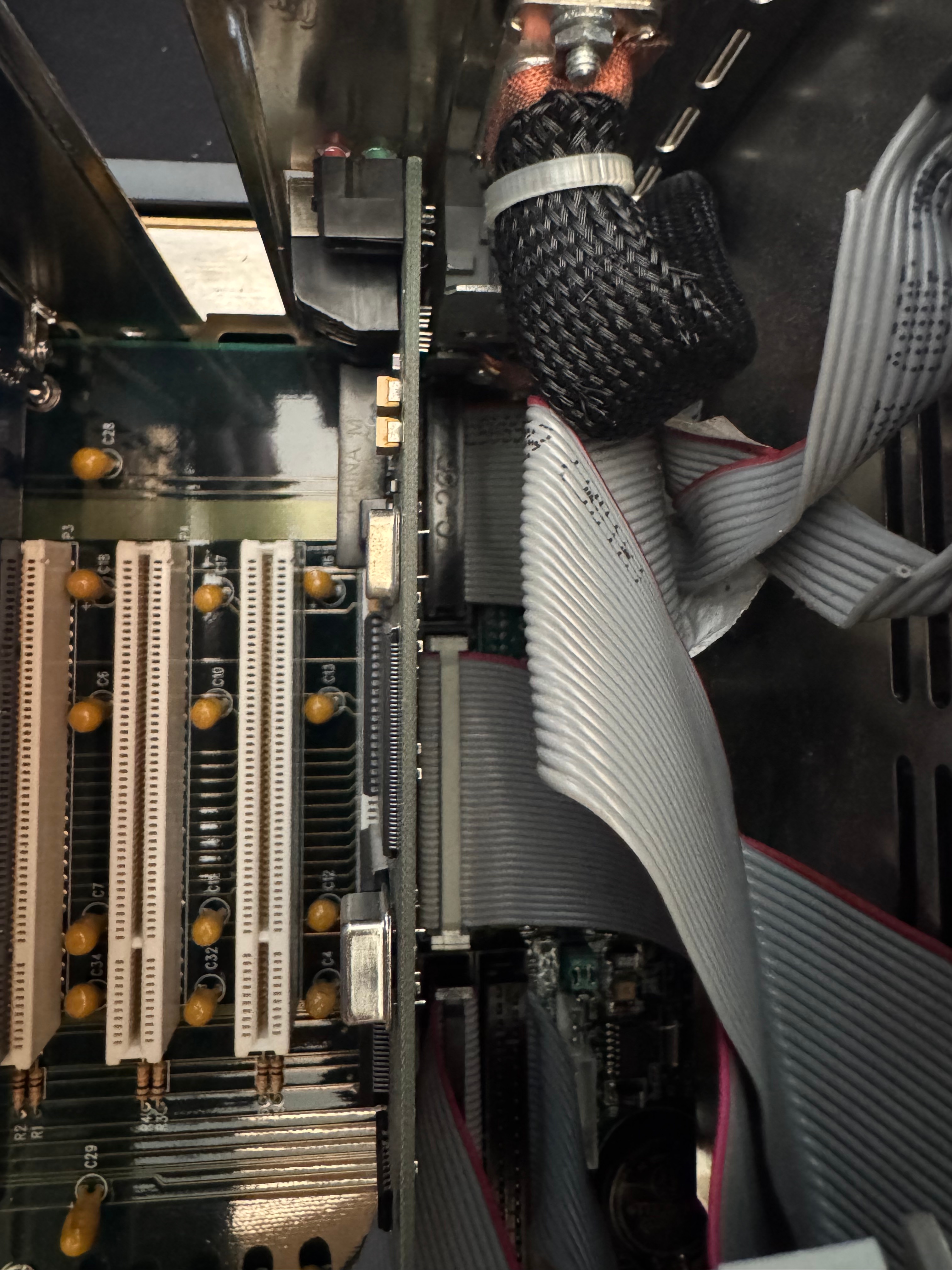
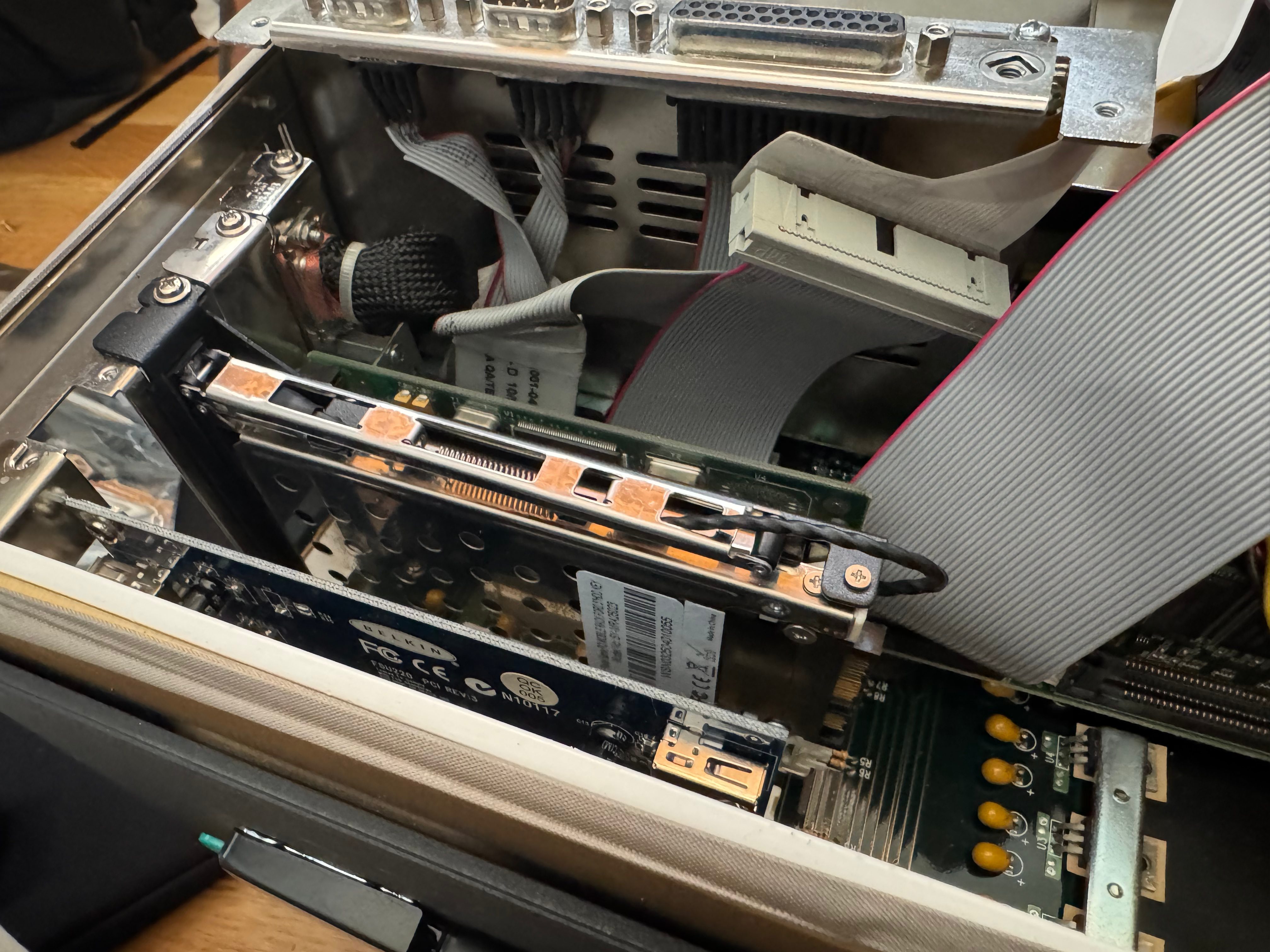
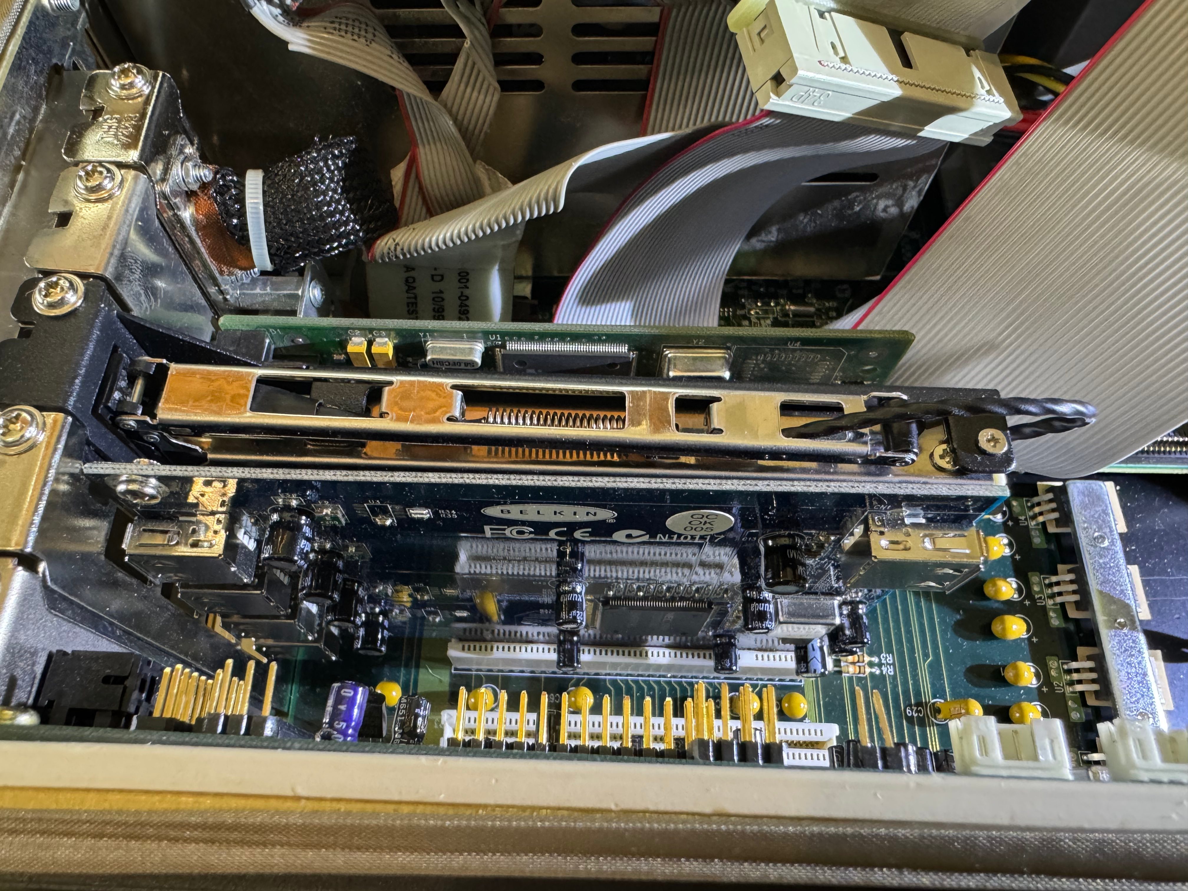
With that, we got the system to POST! It needed a new CMOS battery, but what system this age doesn’t? It was happy! Now I needed a hard drive, some disk drives, and expansion cards. For a hard drive I got a modern SATA SSD, and a SATA to IDE adapter. I put the drive in a spring loaded enclosure that goes into one of the PCI slots; this lets me remove the drive easily if I want to. I would pull the drive to add files before I got networking loaded from time to time. I later added USB, but the system couldn’t boot from that, and burning CDs wasn’t always my go-to.
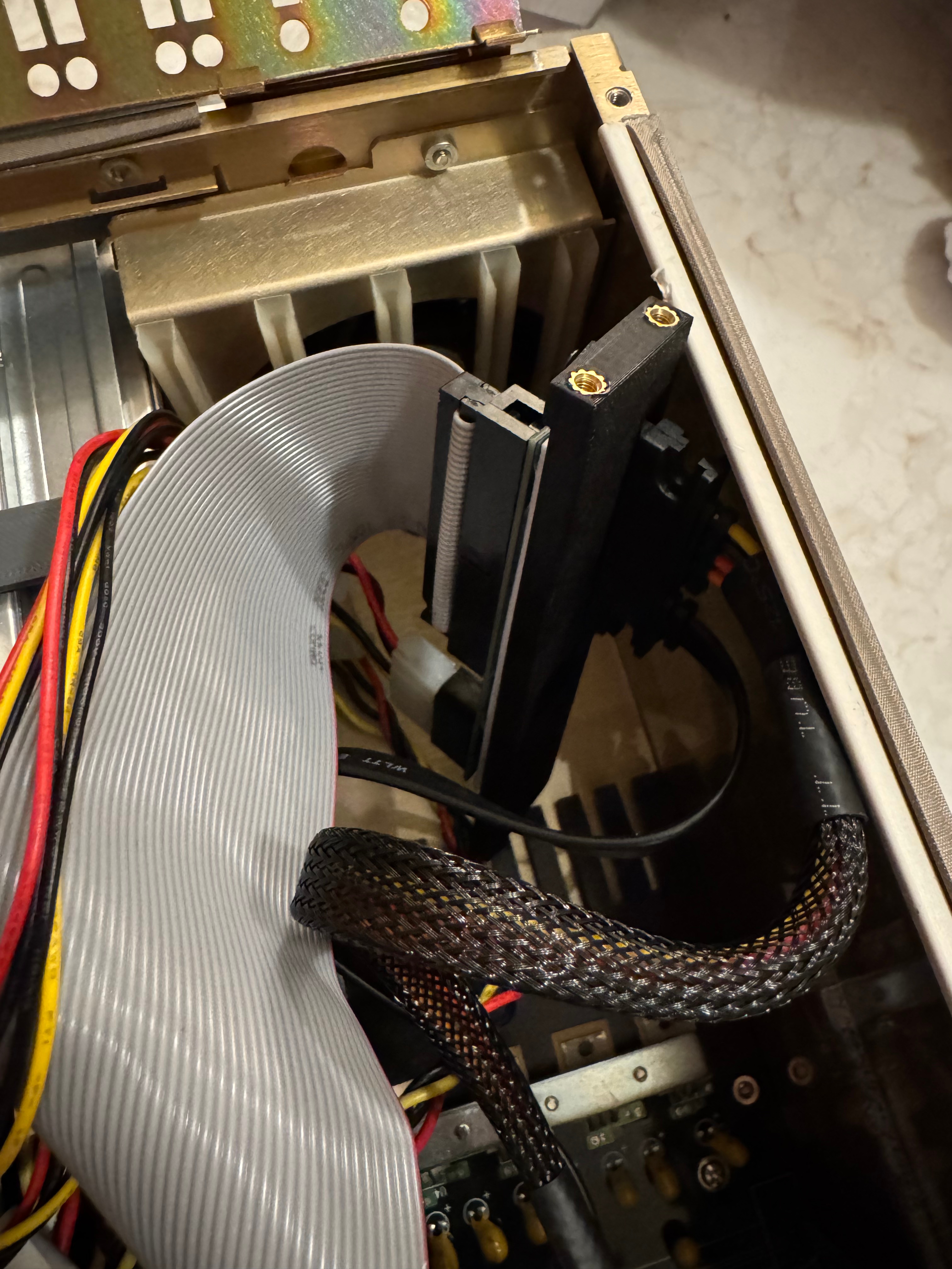
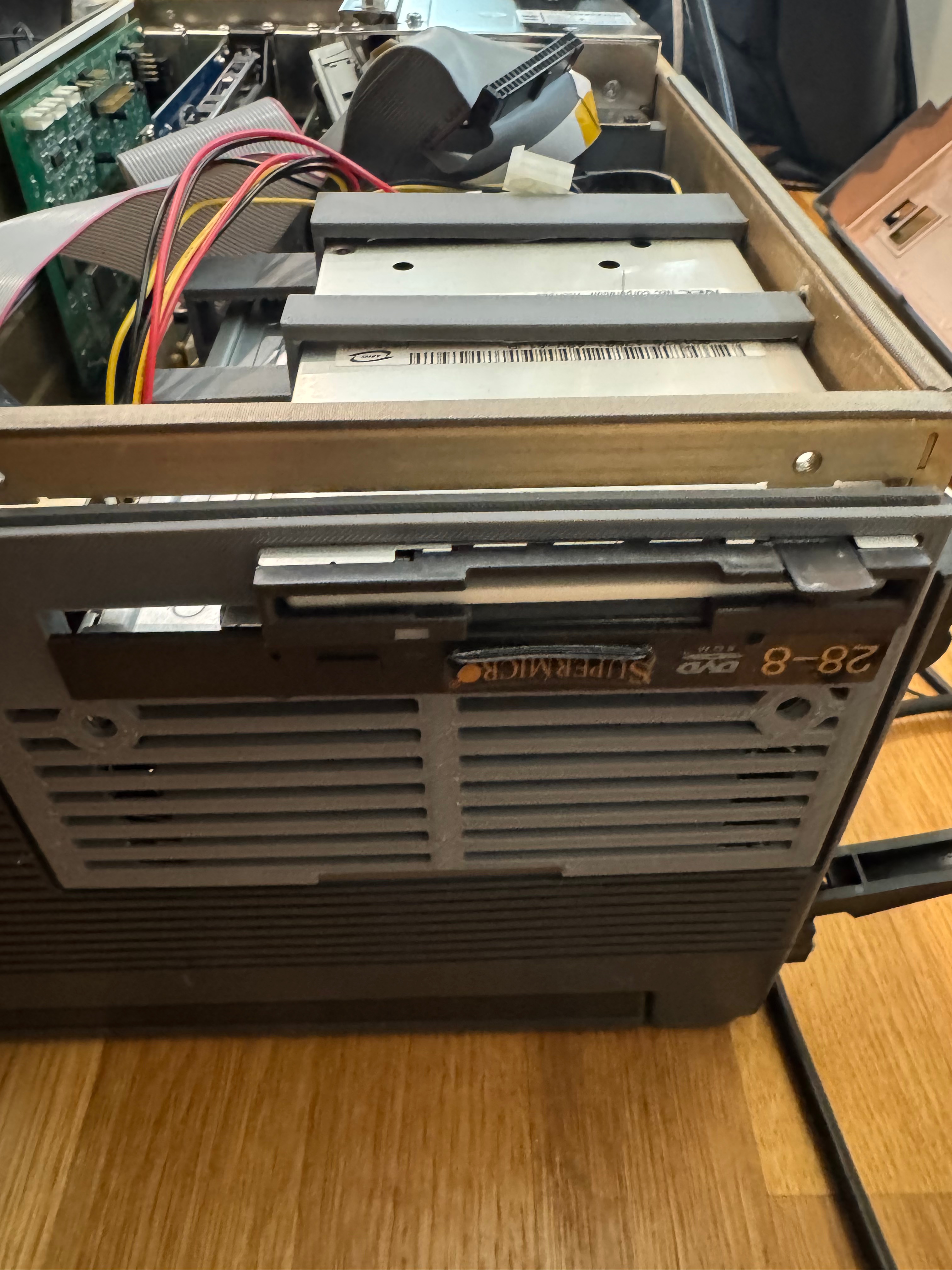
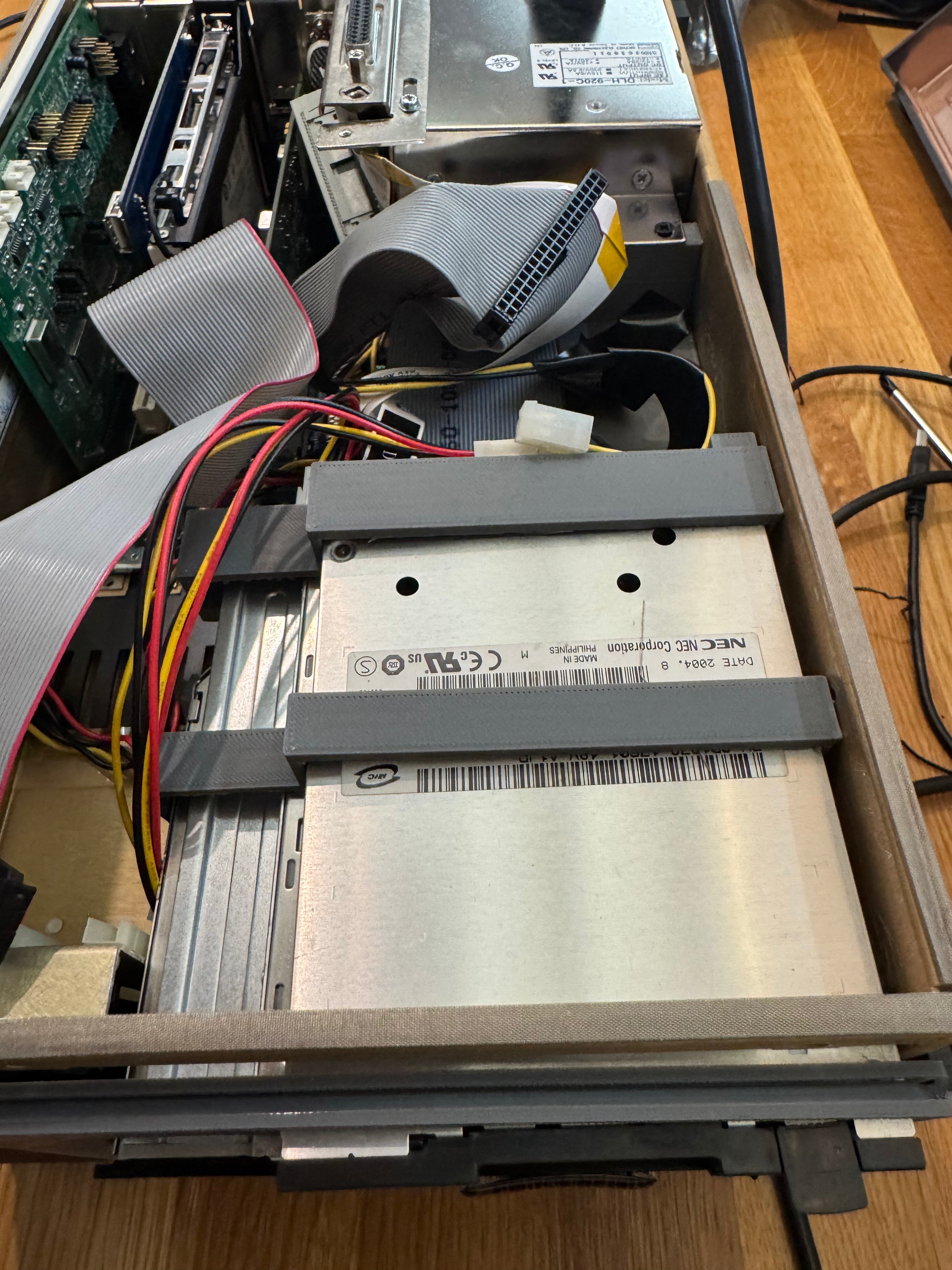
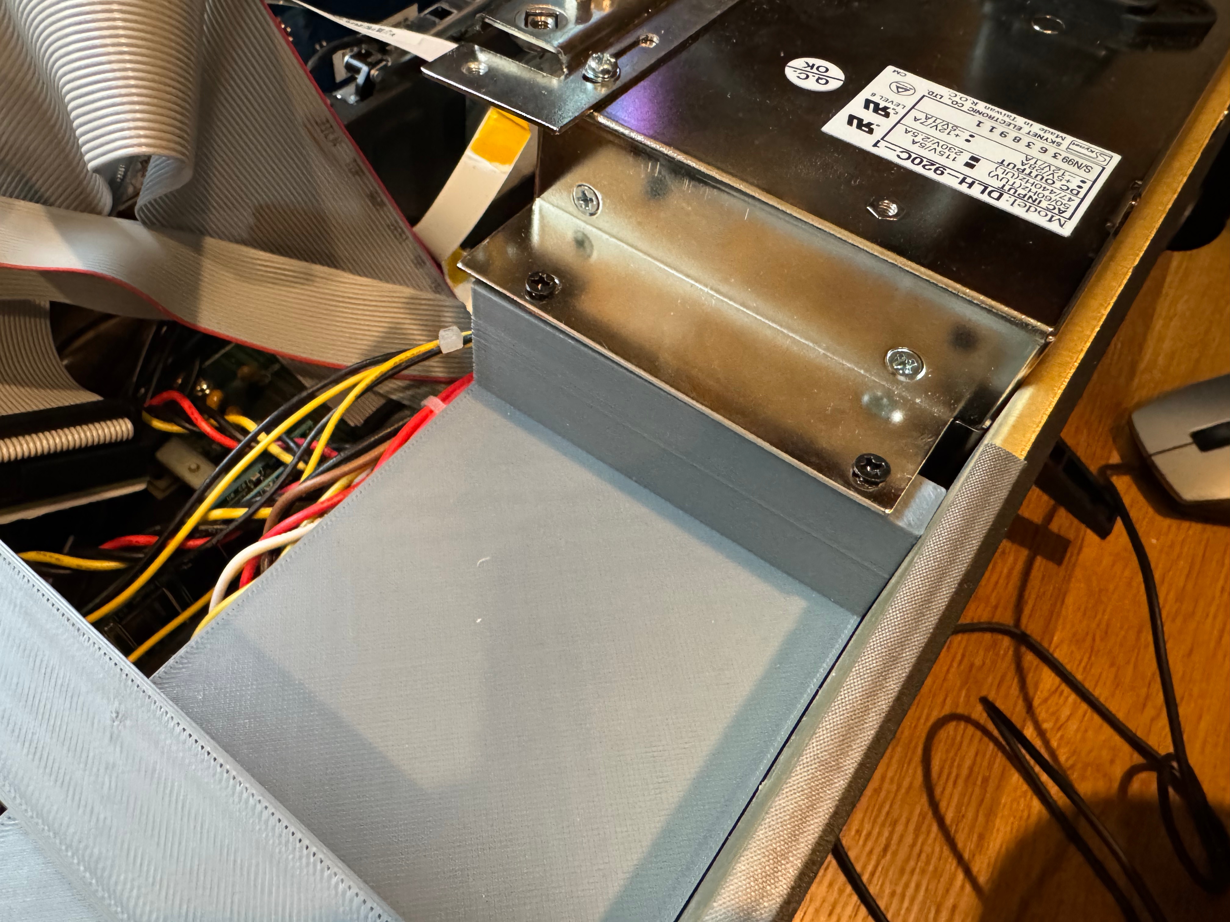
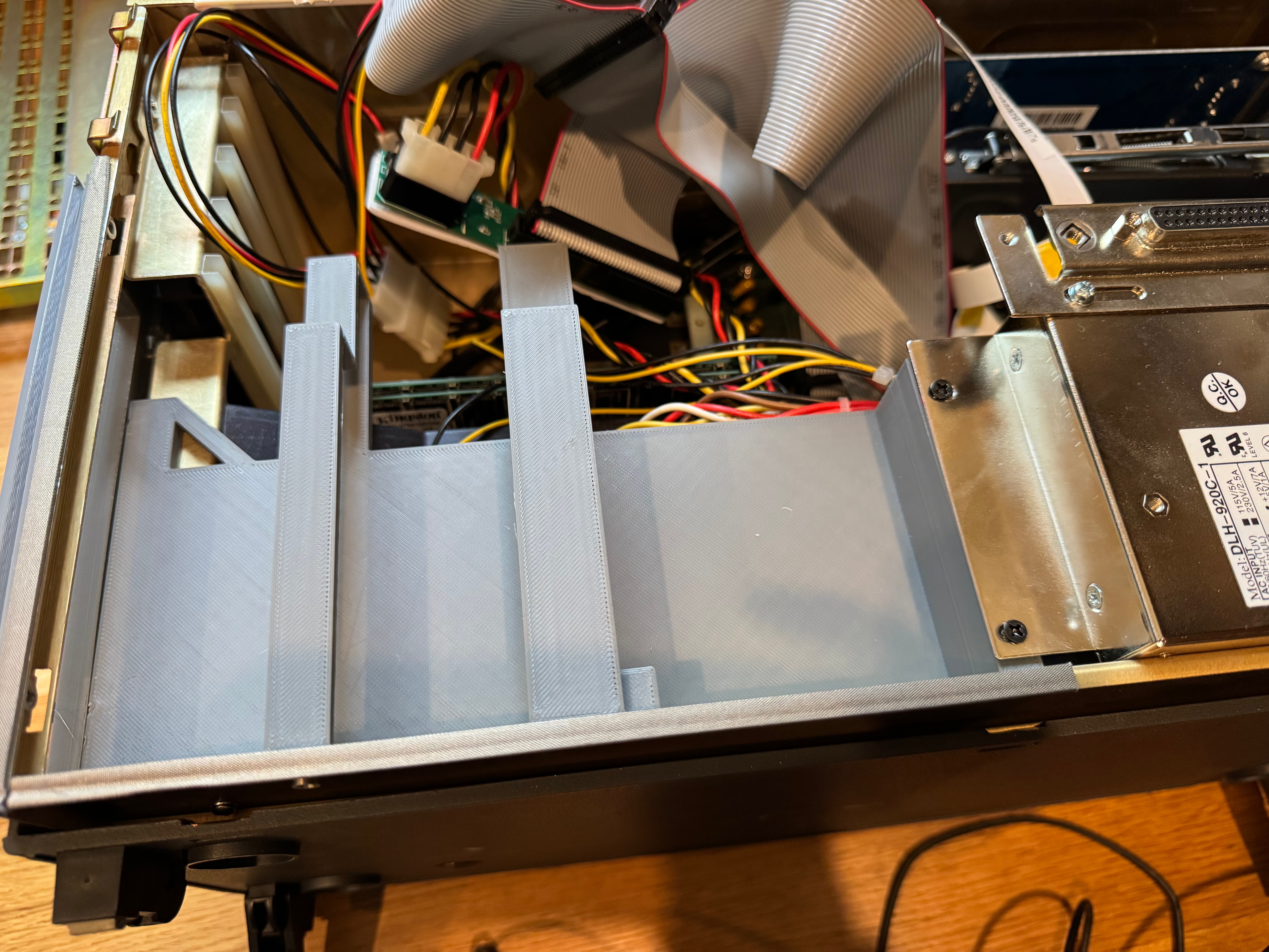
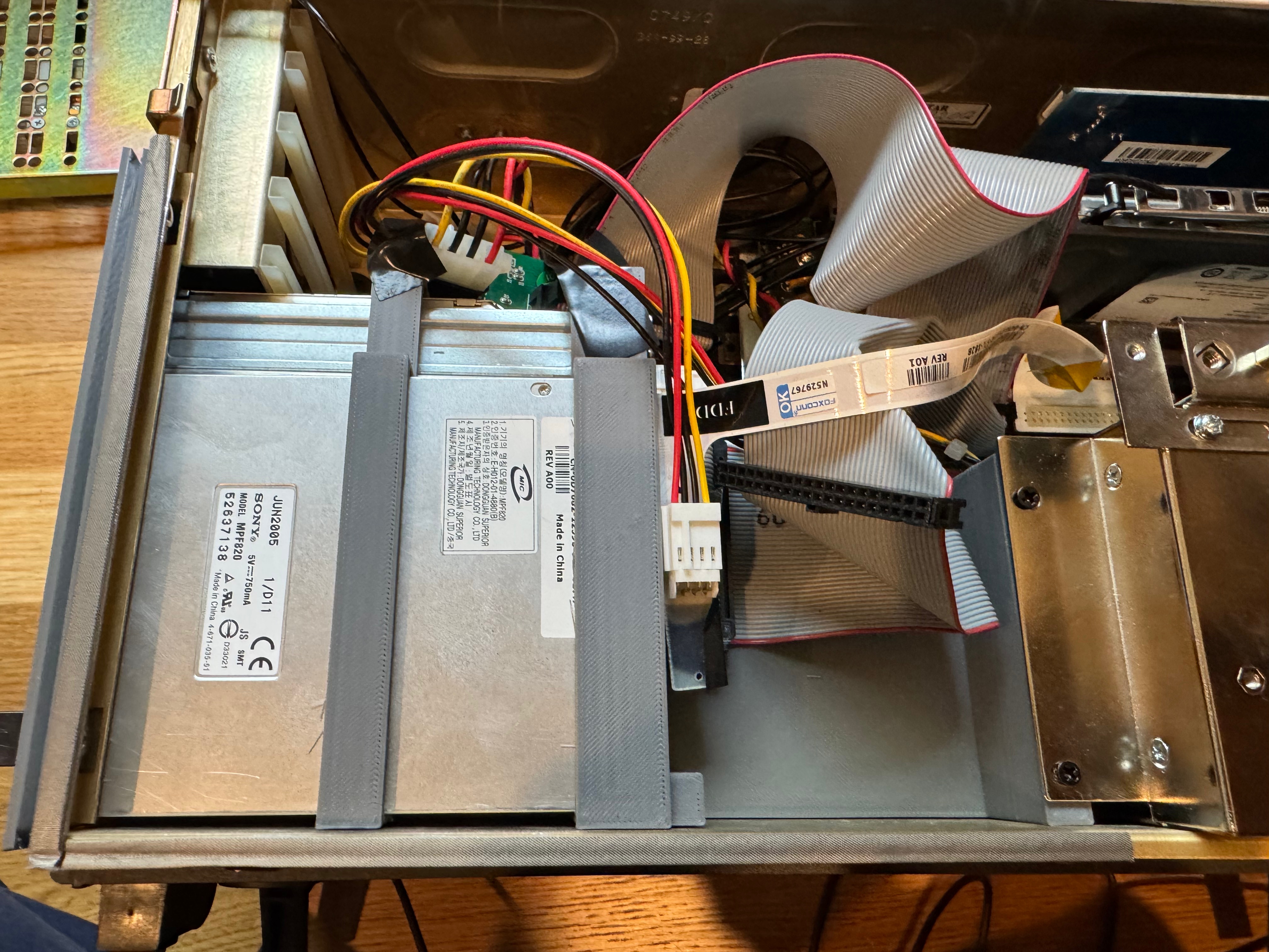
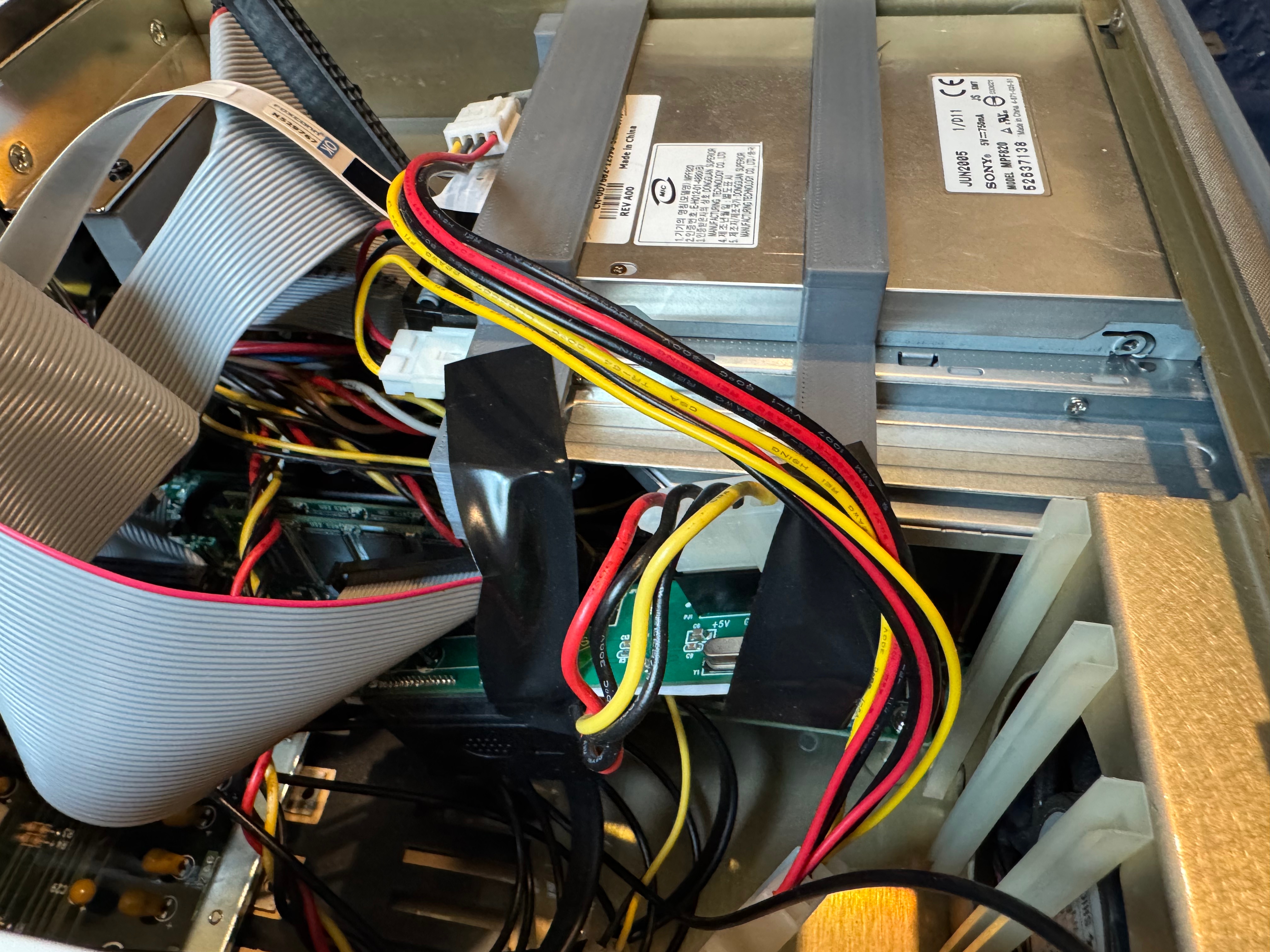
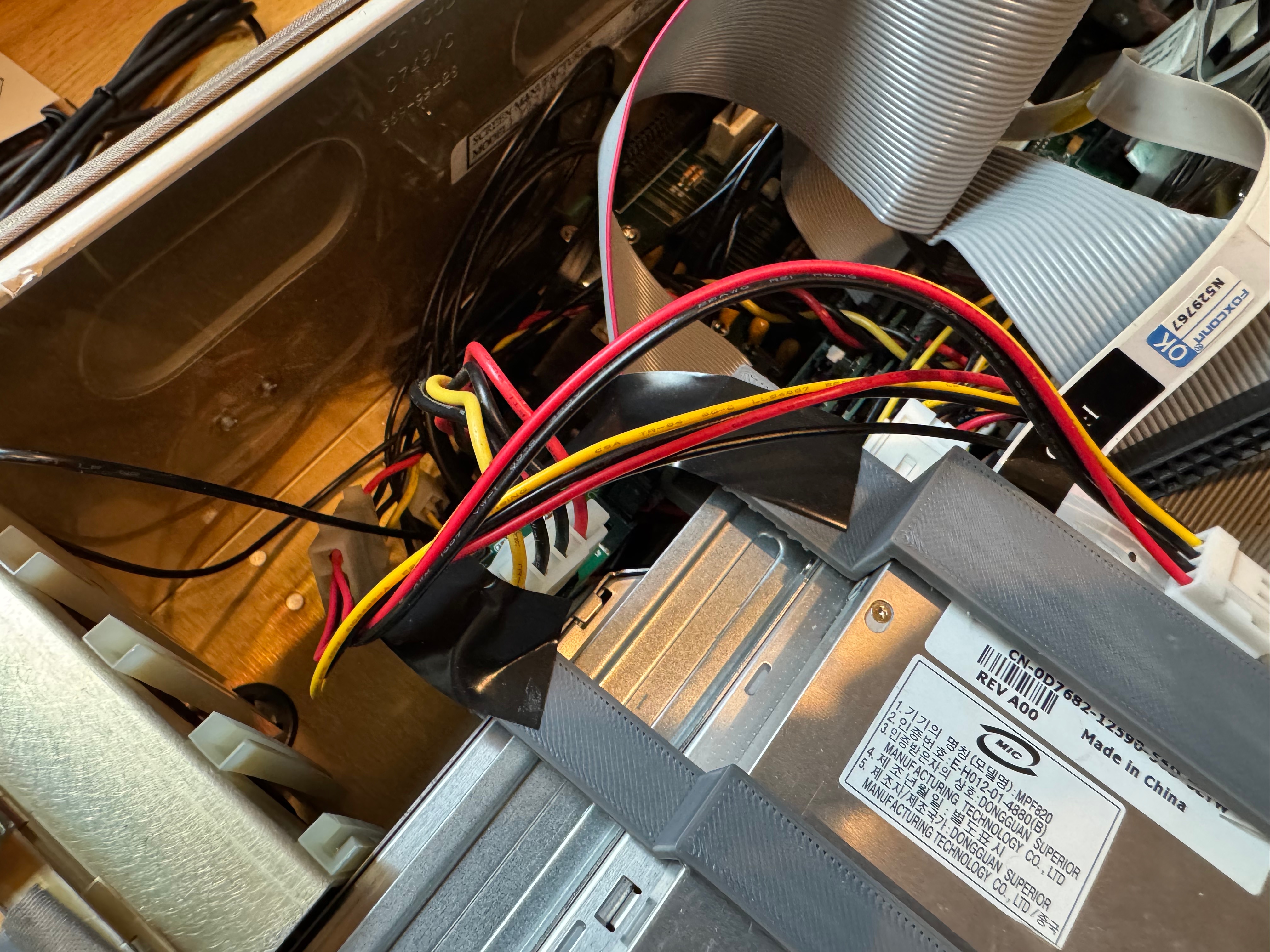
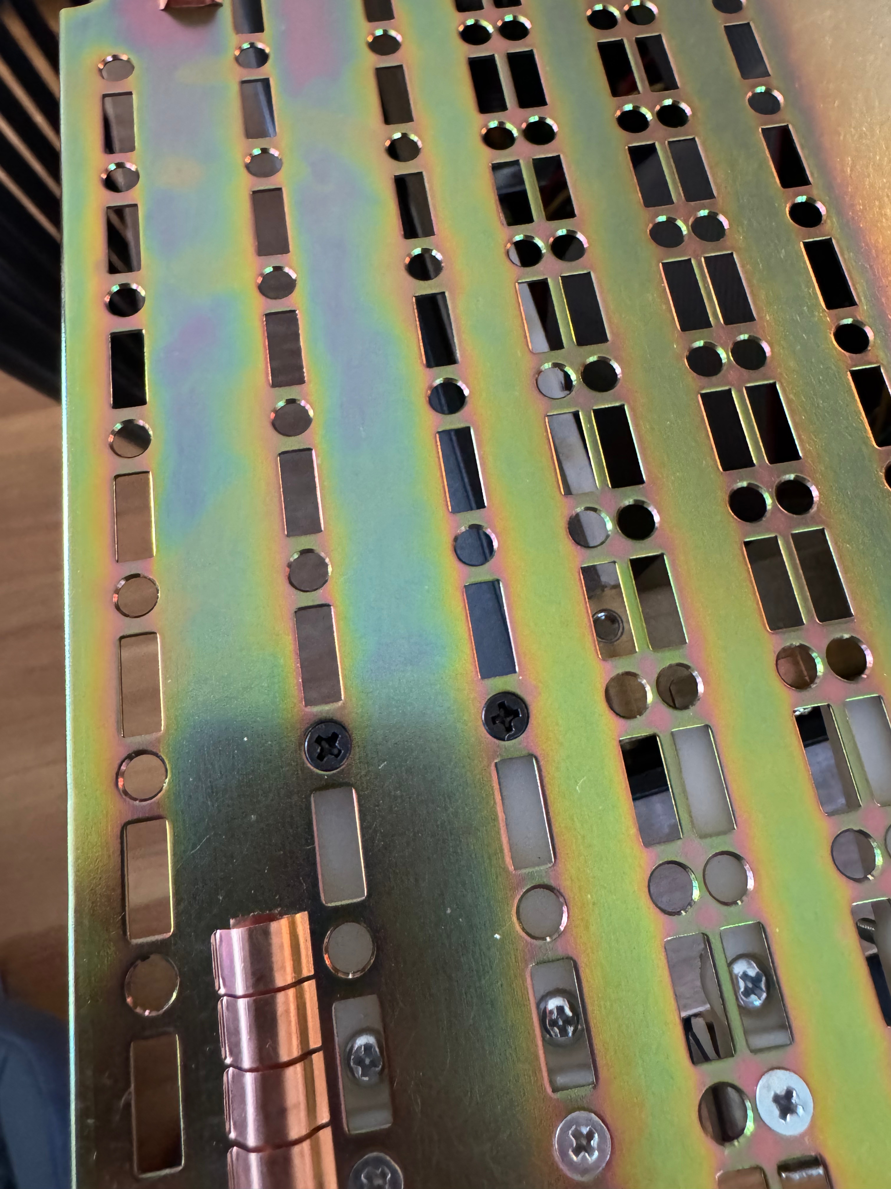
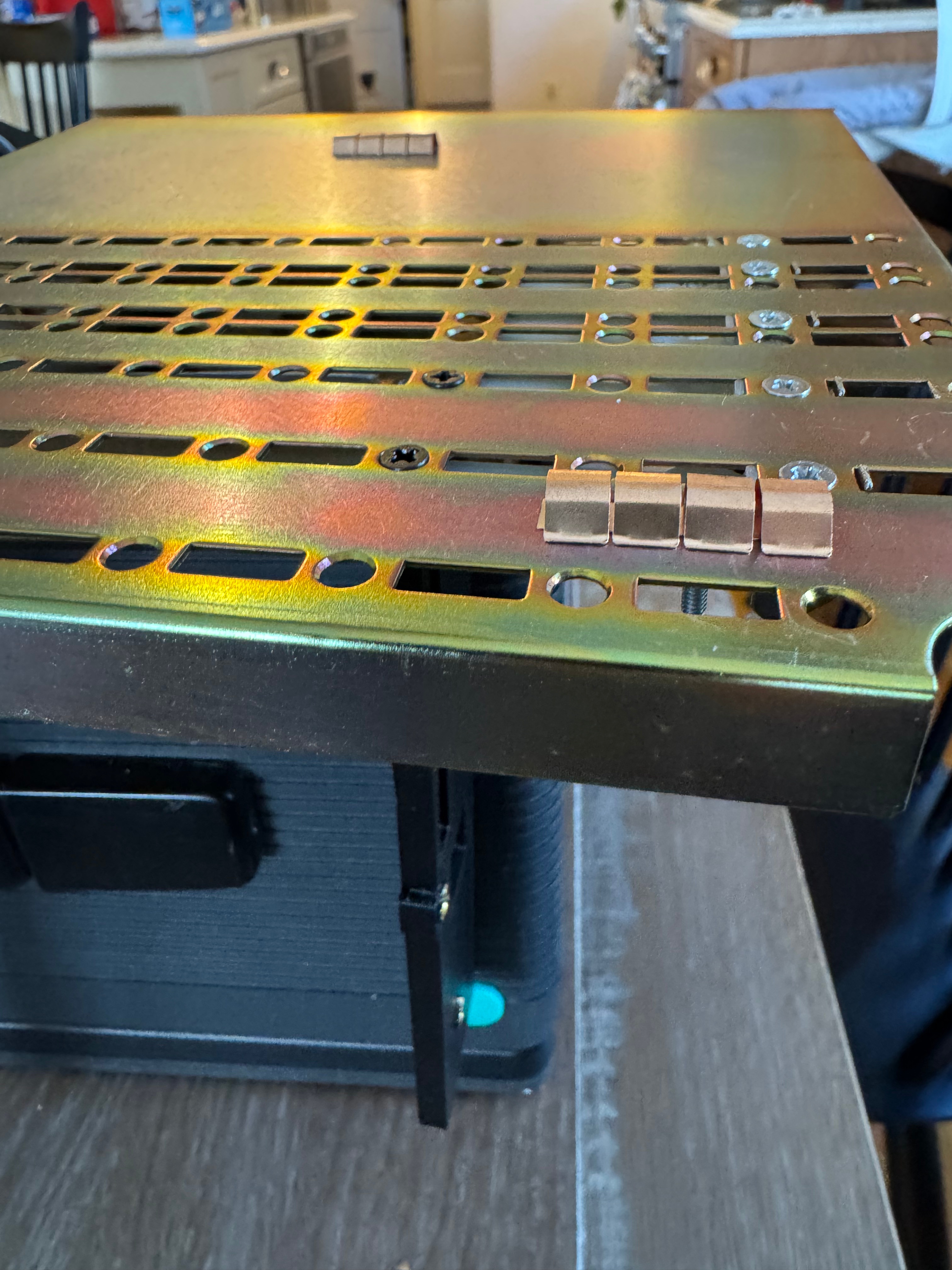
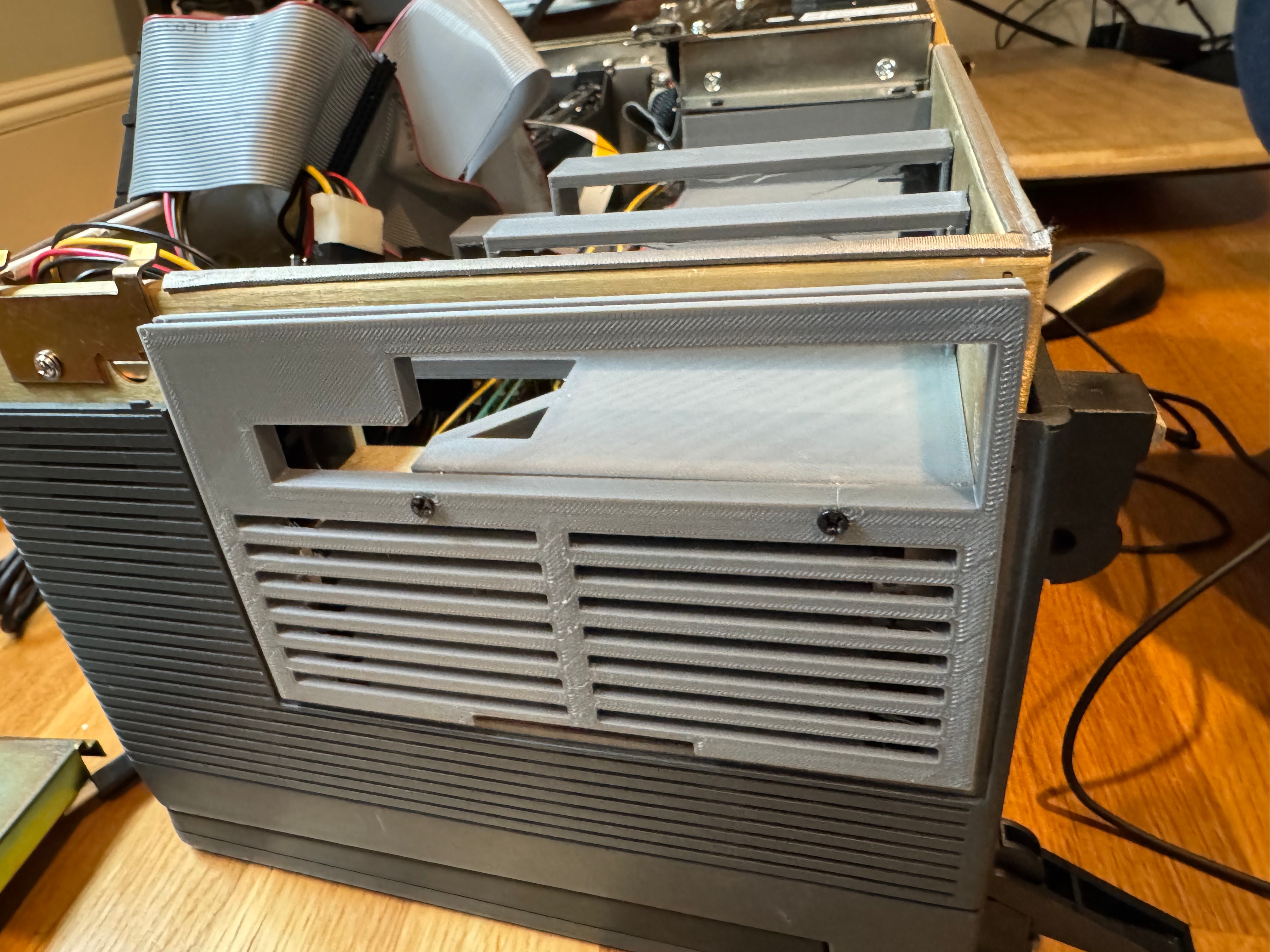
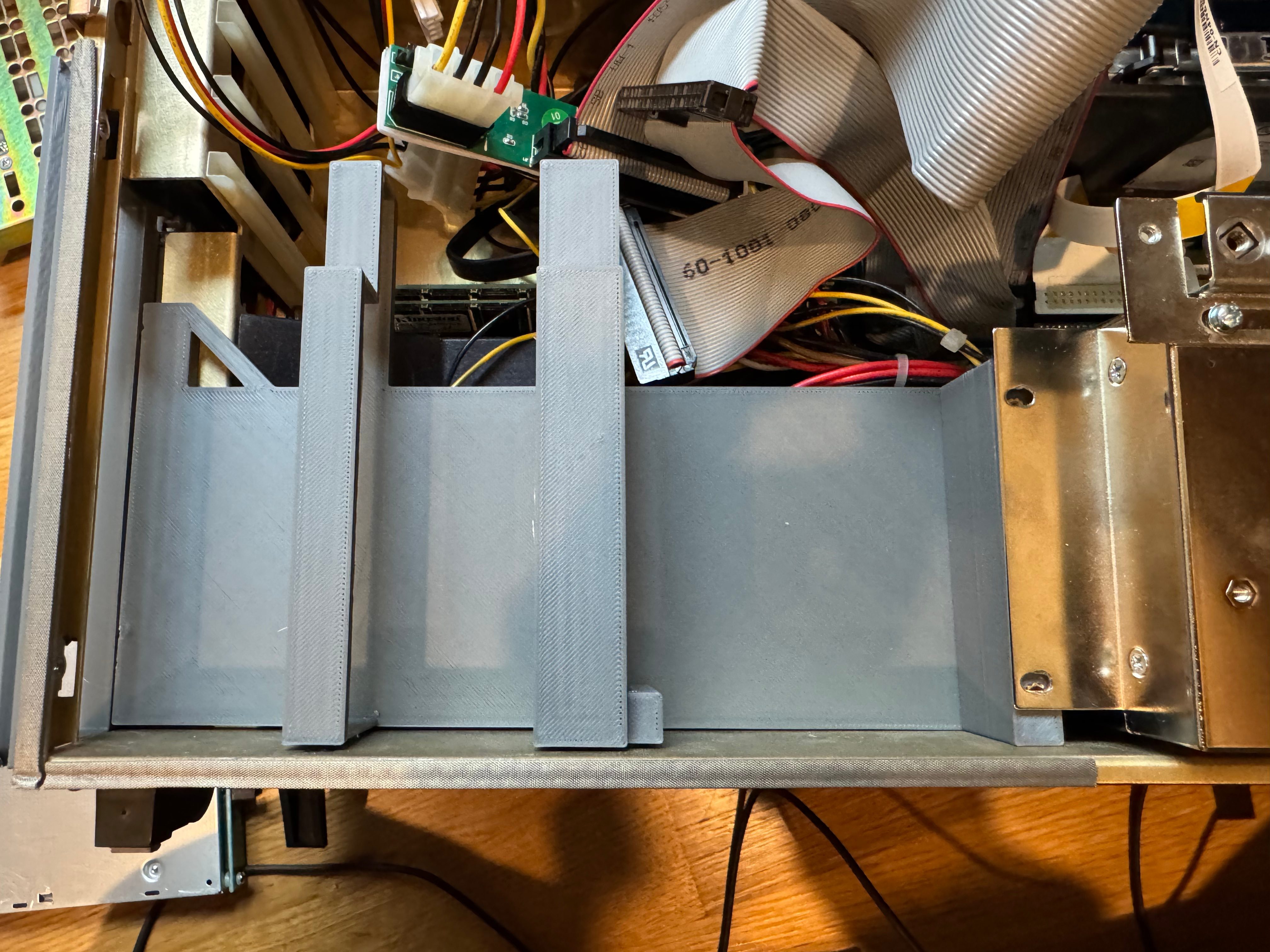
Then I got a slim fit IDE DVD-ROM, and a laptop floppy drive. That let me burn Windows 98 SE to a blank CD and start installation. I also ran memory tests and stress tests on it just to be sure the system in “unknown” condition was doing OK. Now that I had those external drives, I had to start making some brackets. The original hard drive bracket and the optical/floppy bracket were missing when I got the system.

I pondered which operating system to put on the machine. With a 400MHz Pentium II, Windows 95 and 98 were the more obvious choices. The spring-loaded enclosure and optical drive make installing a new operating system not too difficult. To begin its new life (with me) I decided to go with Windows 98 SE. I get USB support right away, FAT32 for more storage, and generally better driver support. There are a lot of community patch kits, Windows Service Packs – PHILSCOMPUTERLAB.COM, that help fix rough edges. Eventually I may install OS/2 for fun, or an older flavor of Linux.

The brackets turned out to be the hardest part of the whole restoration project. The actual system came together so easily that this is where a majority of the time went: dialing in the models for all the brackets.
I then went to find some additional expansion cards to make my life easier, starting with a Belkin F5U220 USB 2.0. With USB mouse and storage support added, working within Windows 98 would be much easier. The little nub mouse works on the keyboard, but it’s not the most comfortable thing to use.

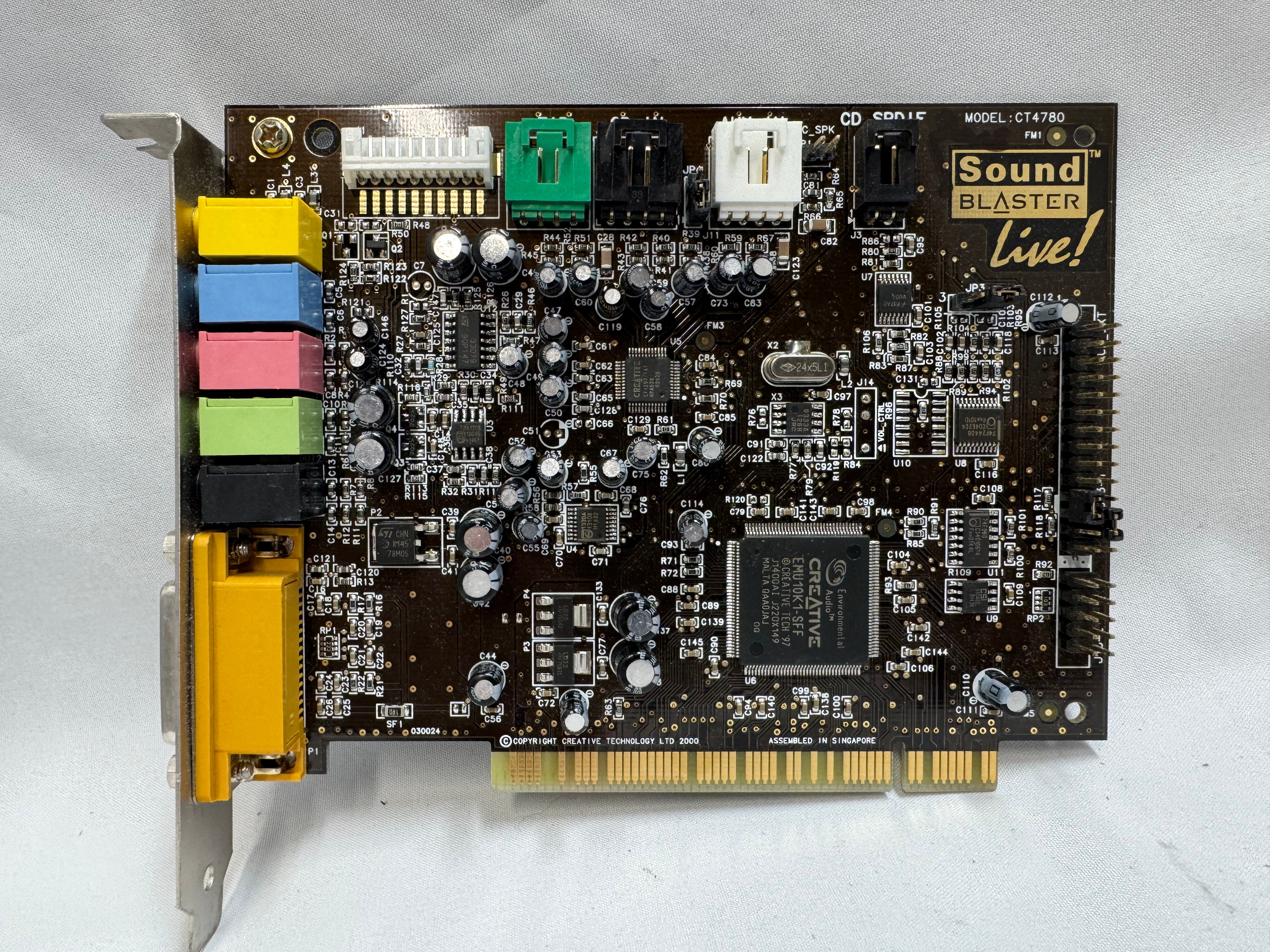
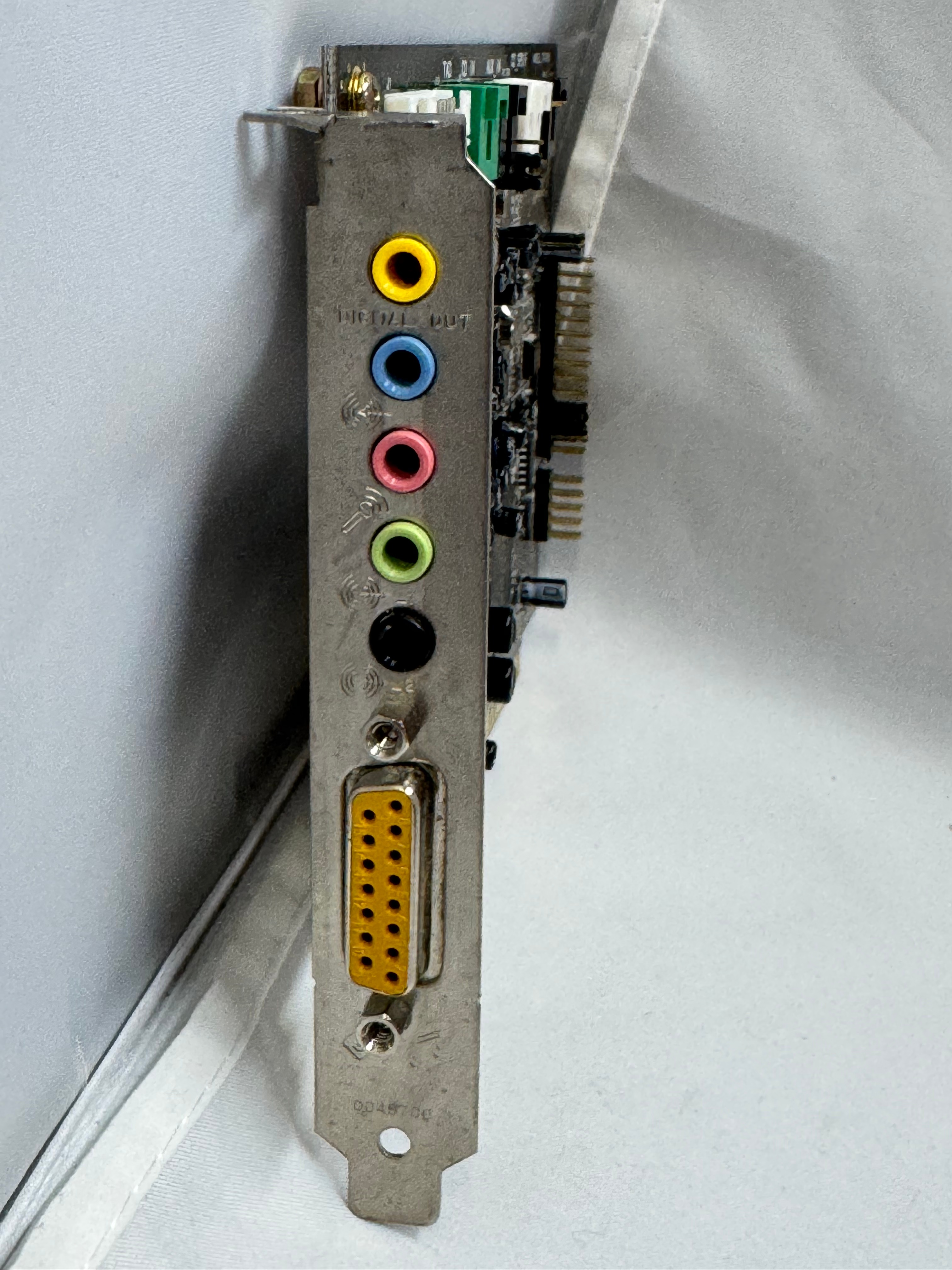
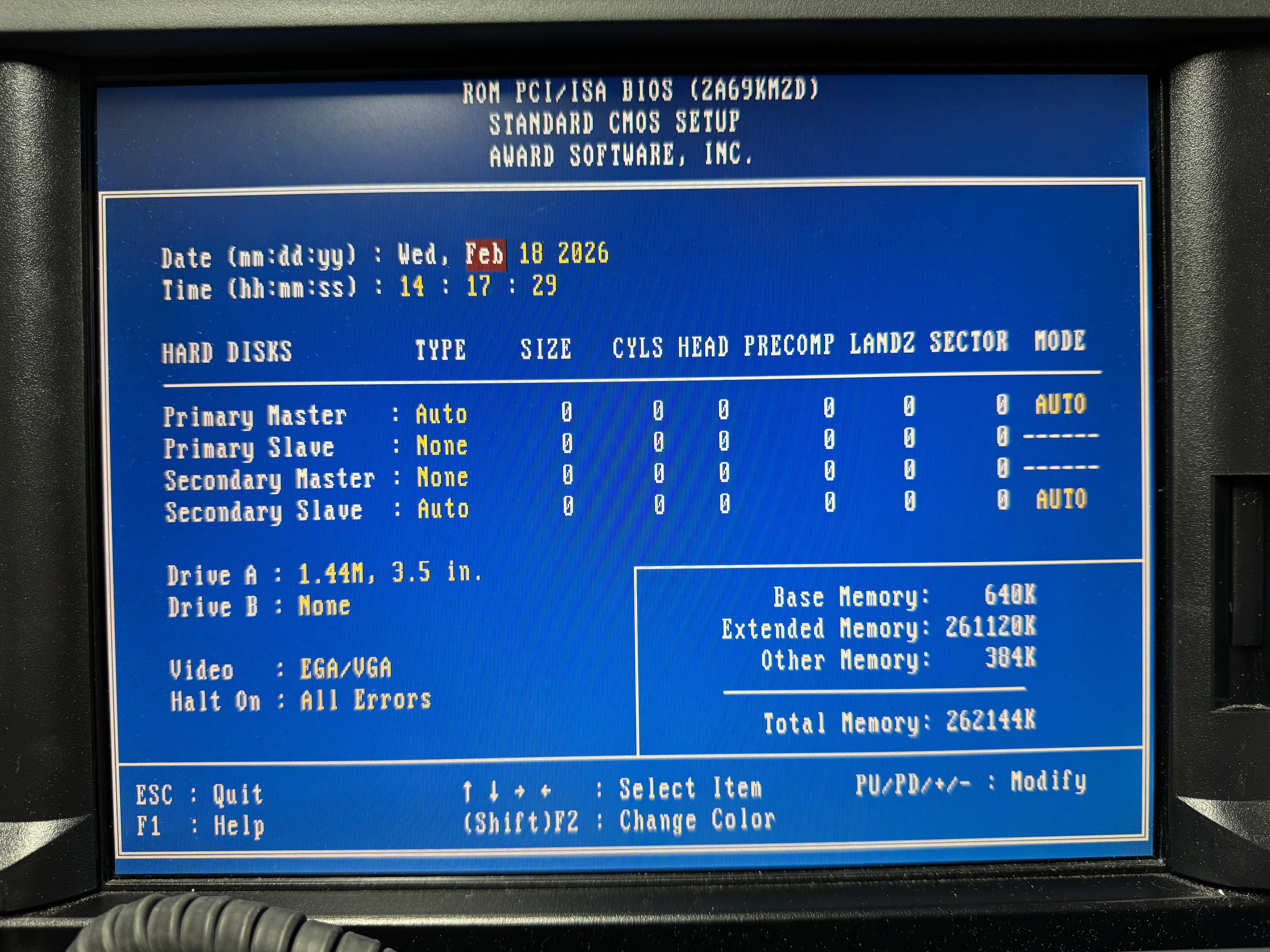
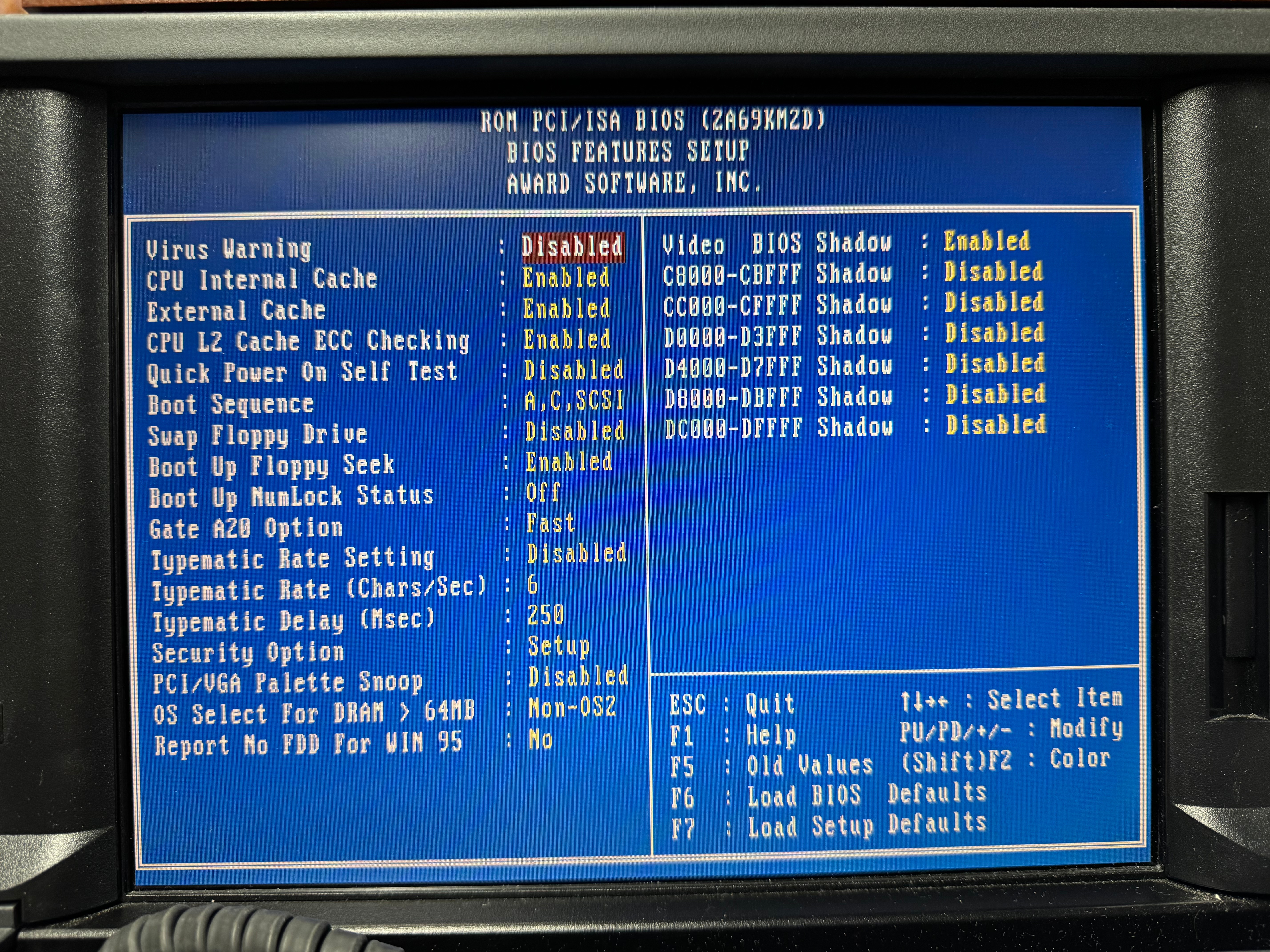
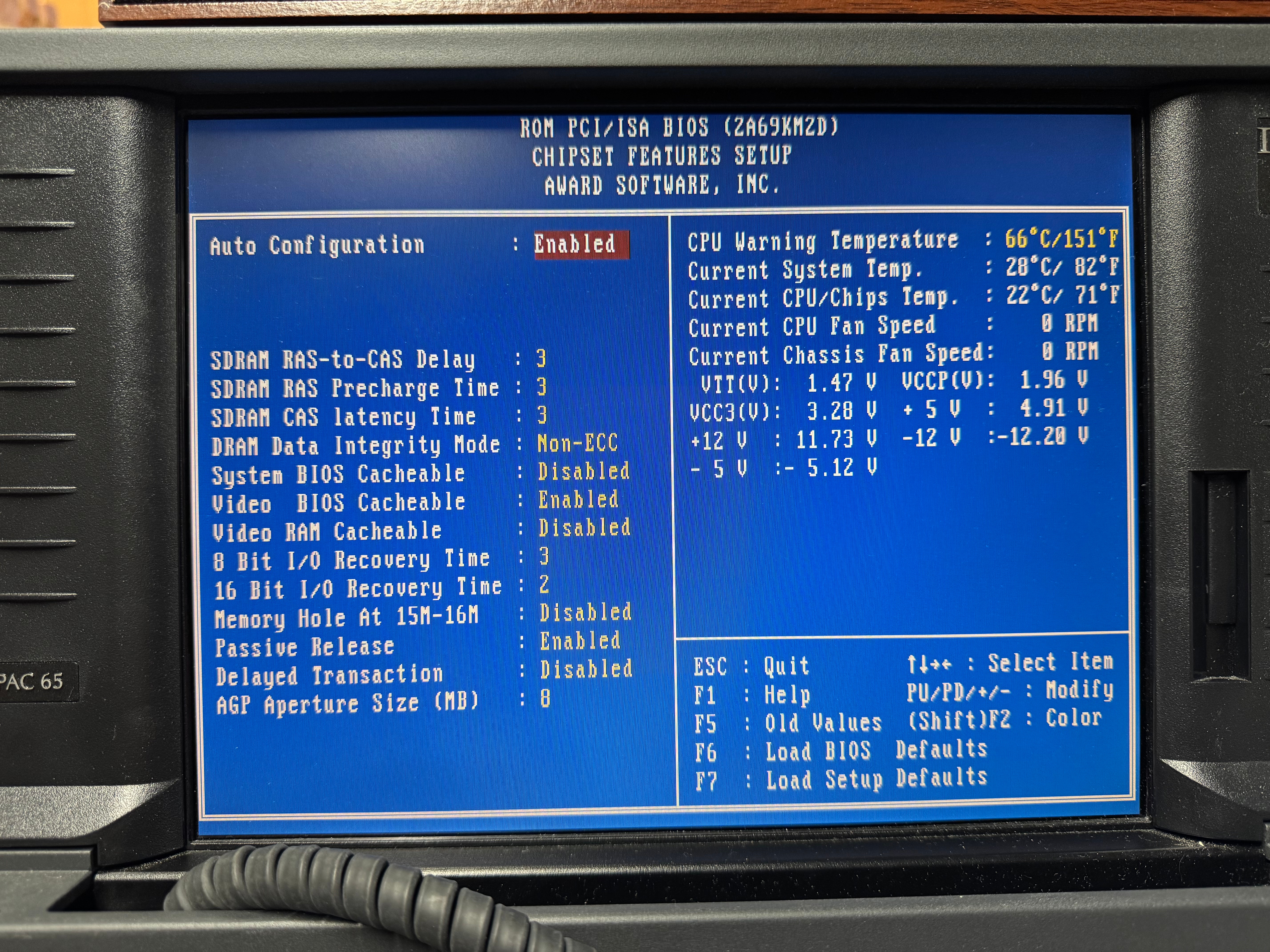
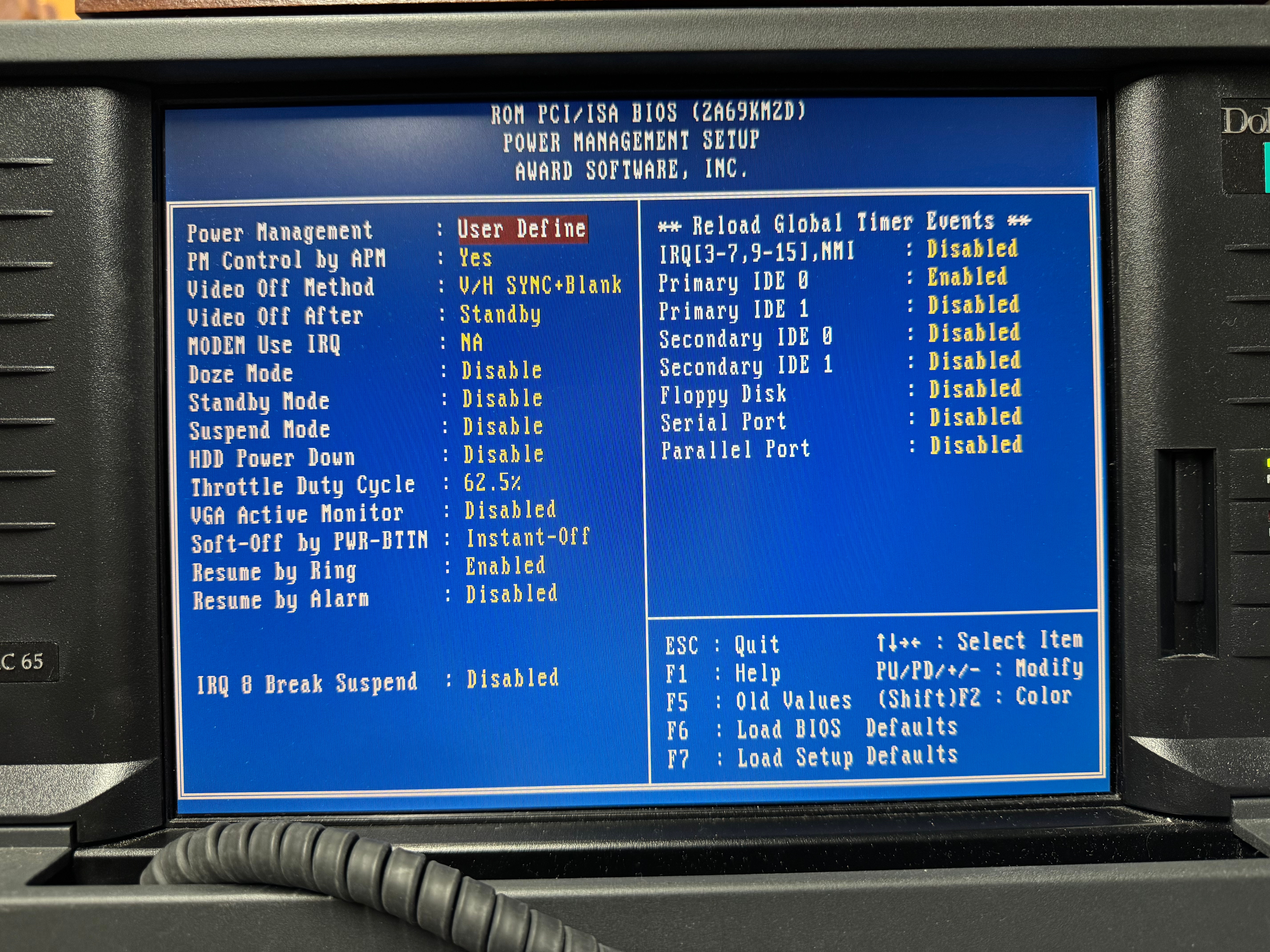
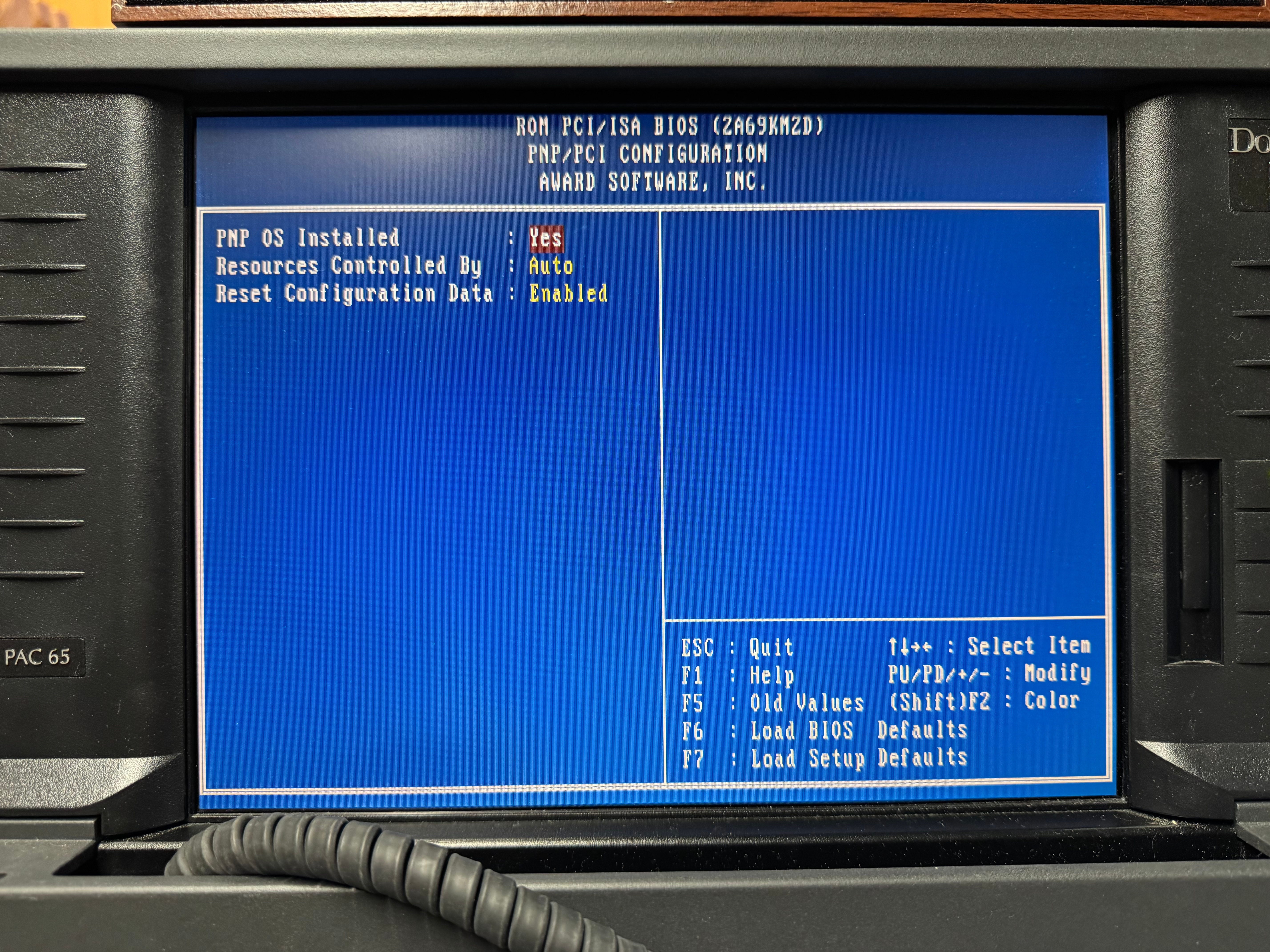
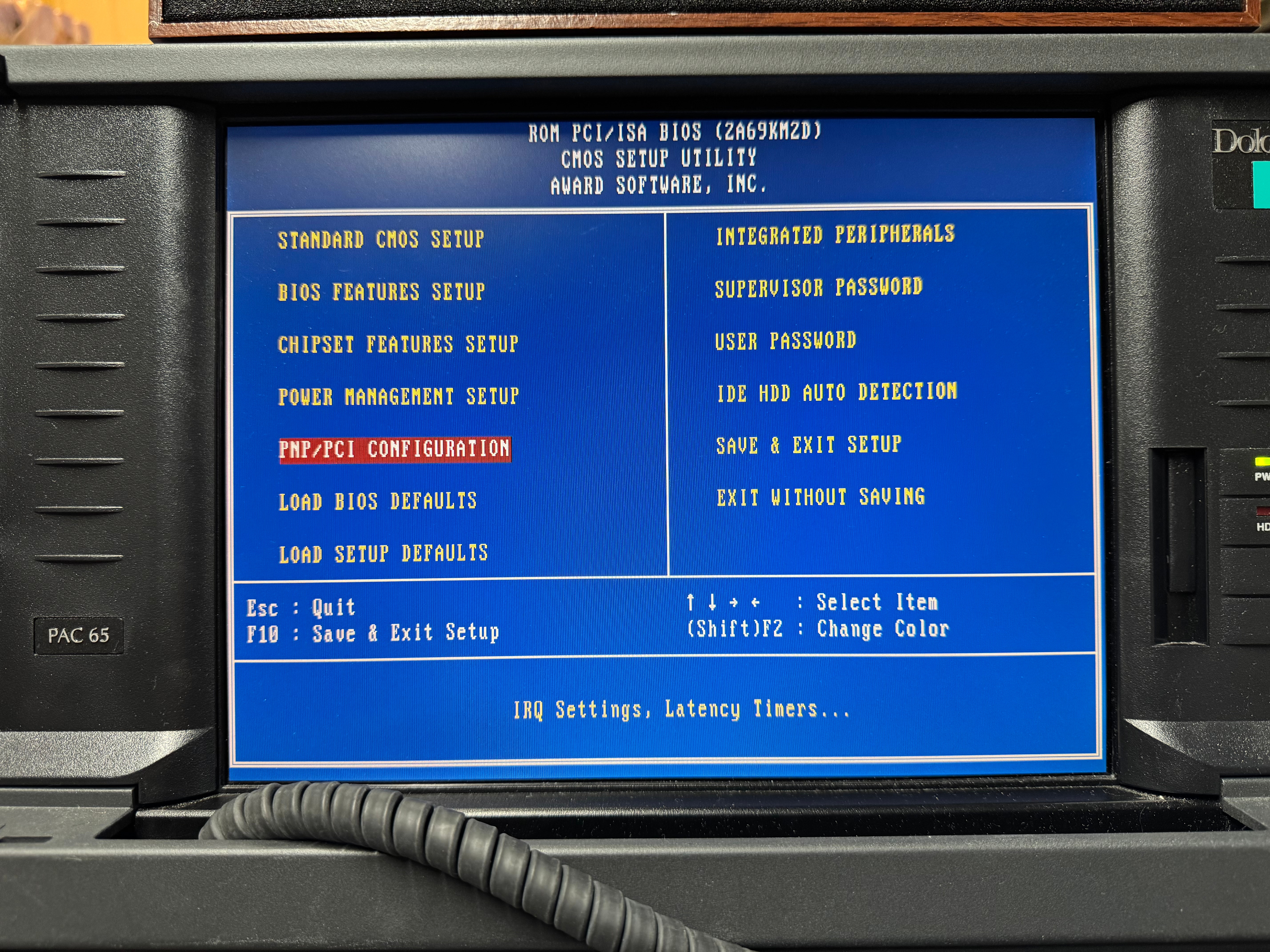
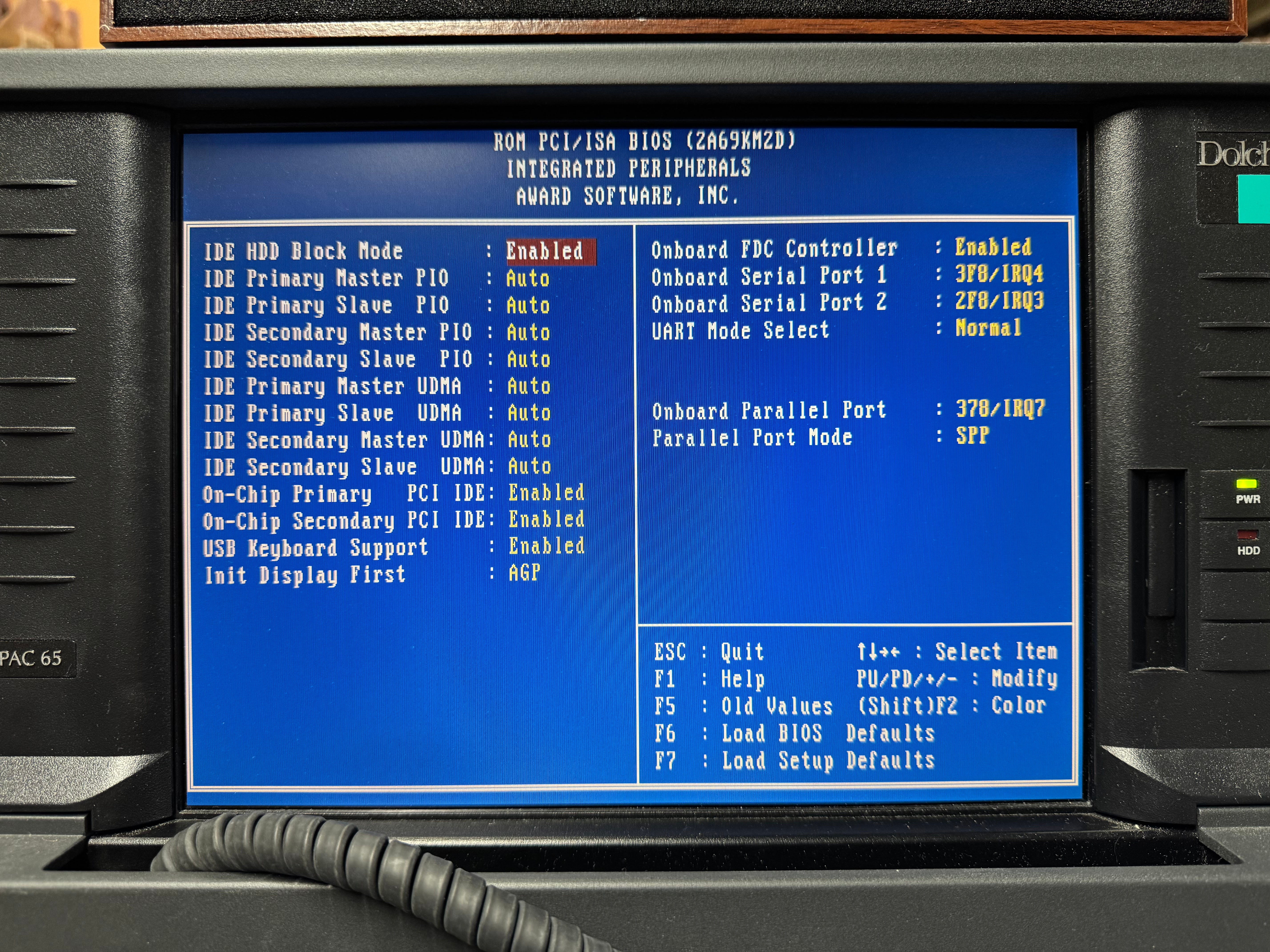
I wanted to get a Creative Sound Blaster, and I did off eBay. It was an authentic, old, ISA one that would work perfectly with all my DOS games. The issue I ran into was the ISA slot did not want to work. I am not sure if this is a later model, or maybe there is a jumper I couldn’t find on the motherboard that needs to be set for the ISA slot to work. There are many BIOS screens (screenshots below). I tried manually setting IRQ, automatic, no matter what Windows didn’t even see the card existed. After battling that for a little while, I gave in and got a PCI Sound Blaster. Using Windows 98 made this easier than older operating systems would have. That one worked immediately when plugged in.

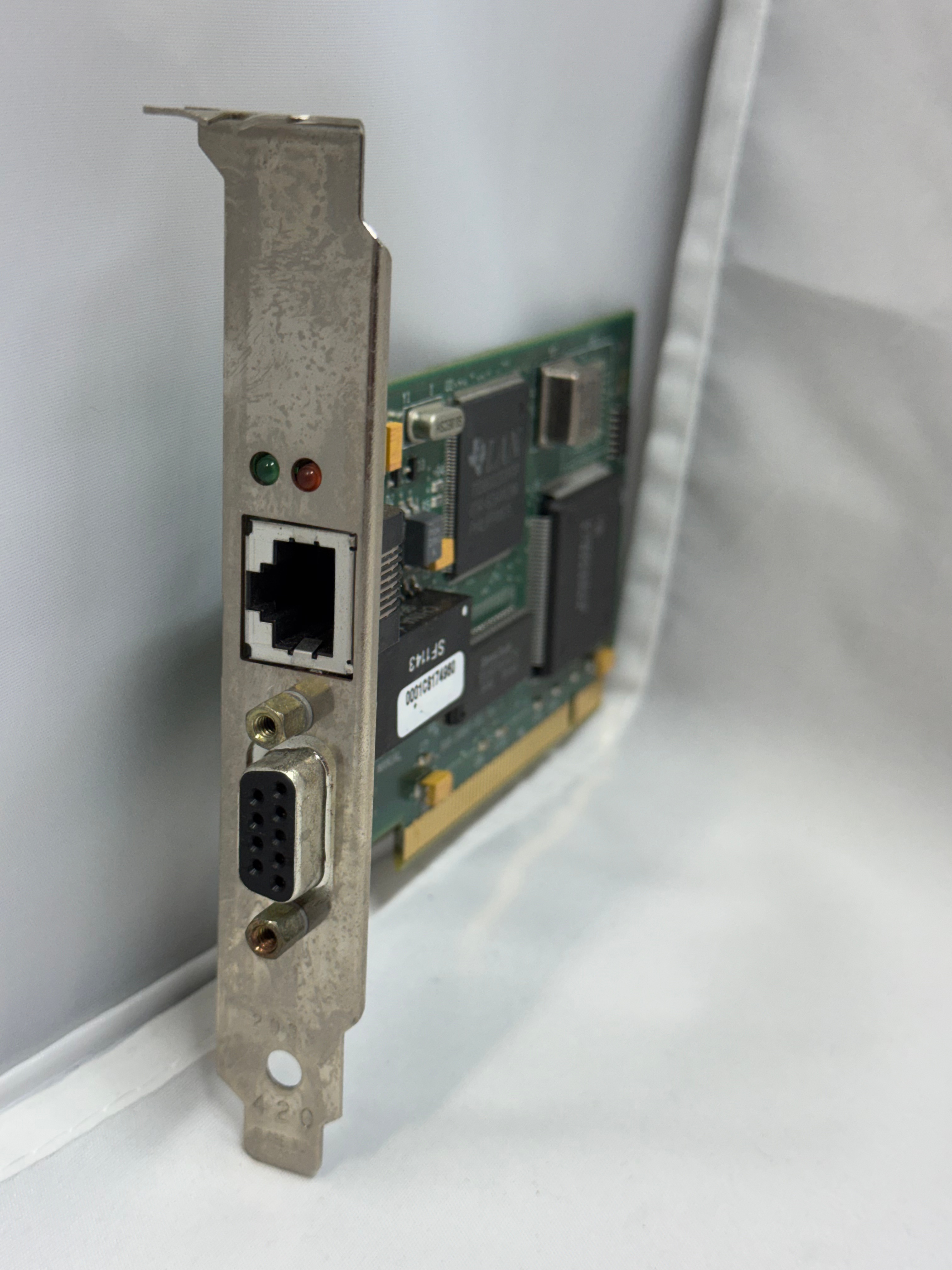
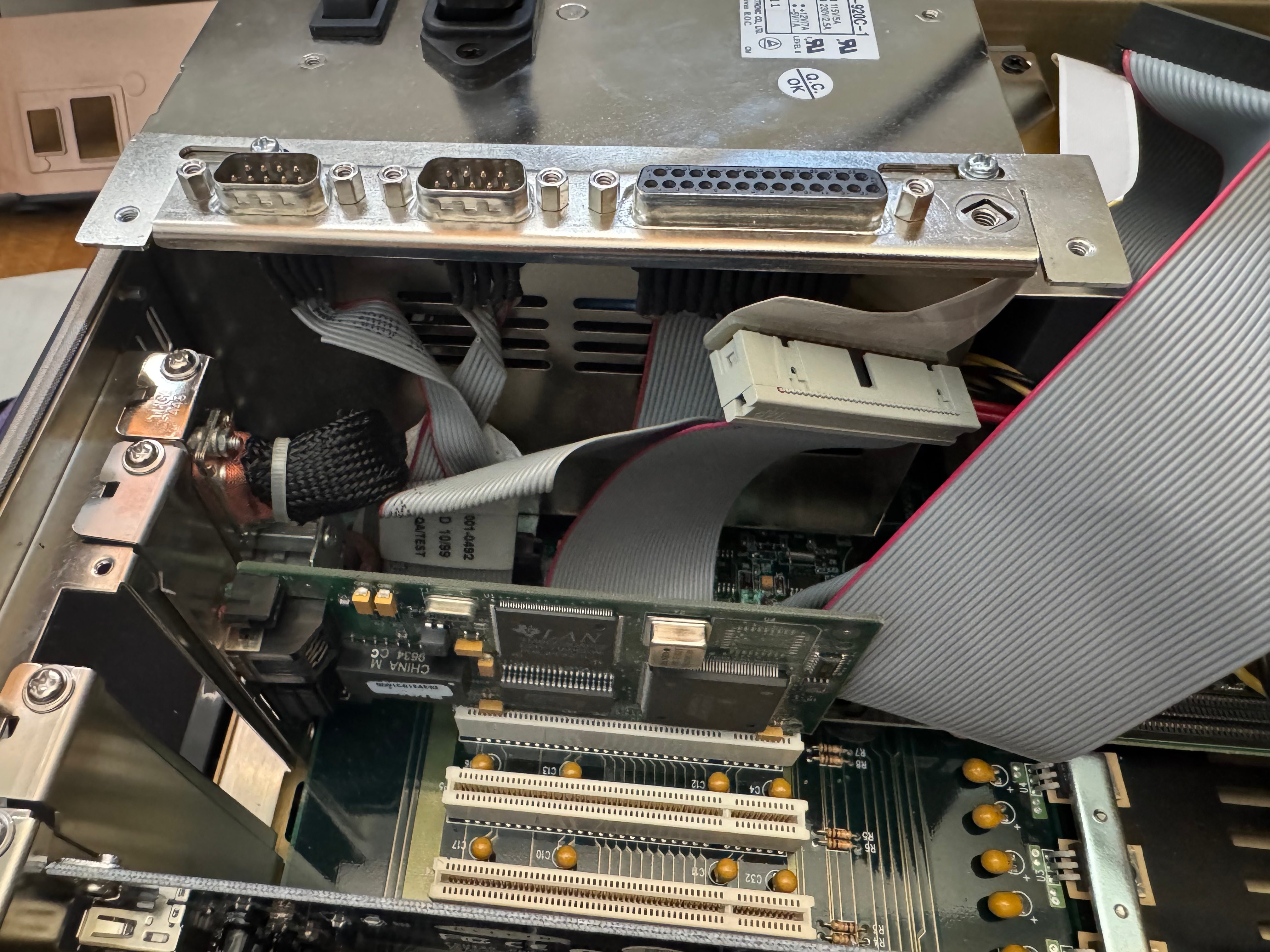
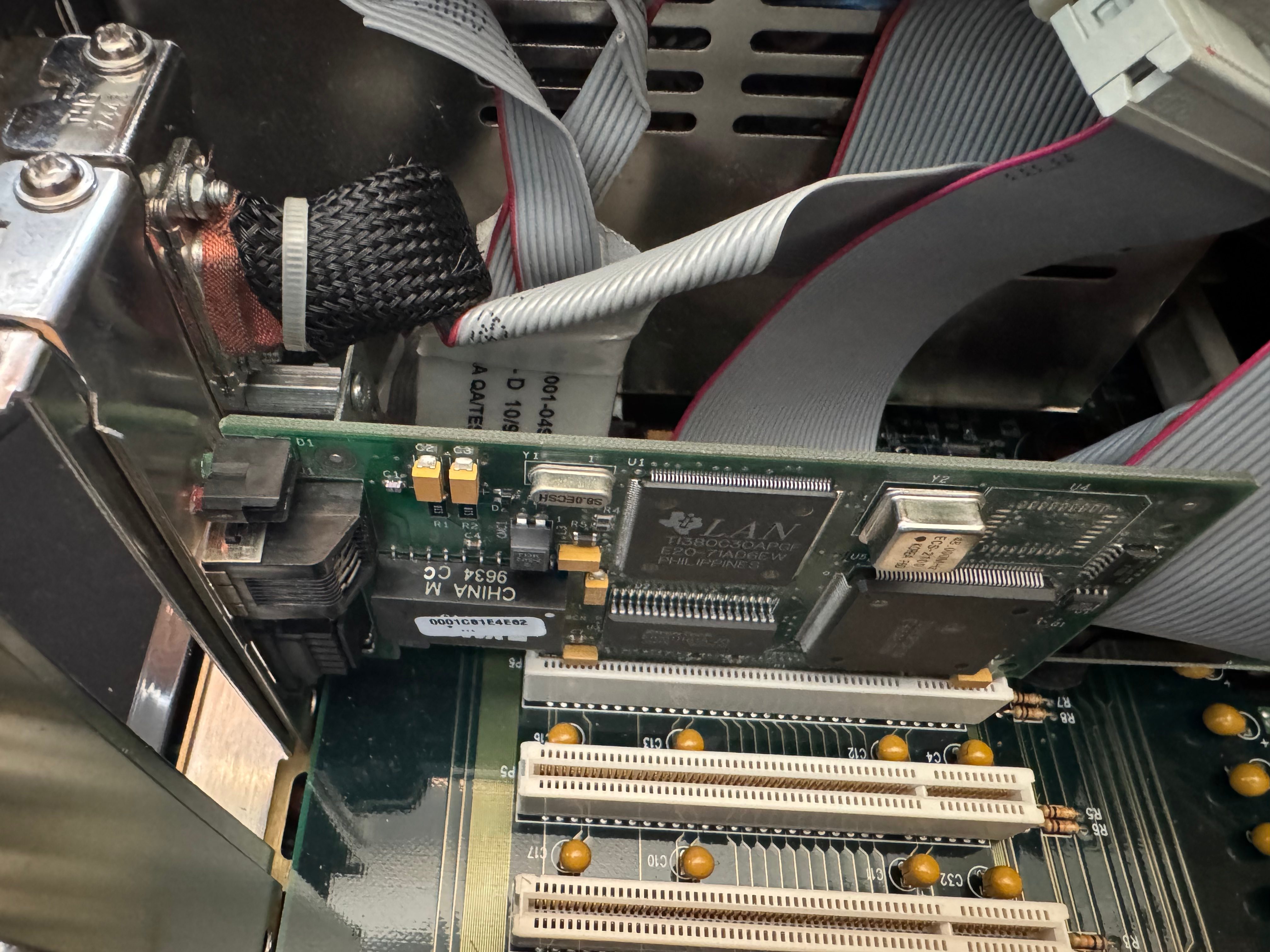
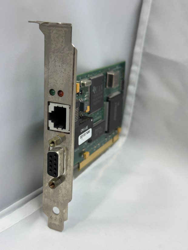
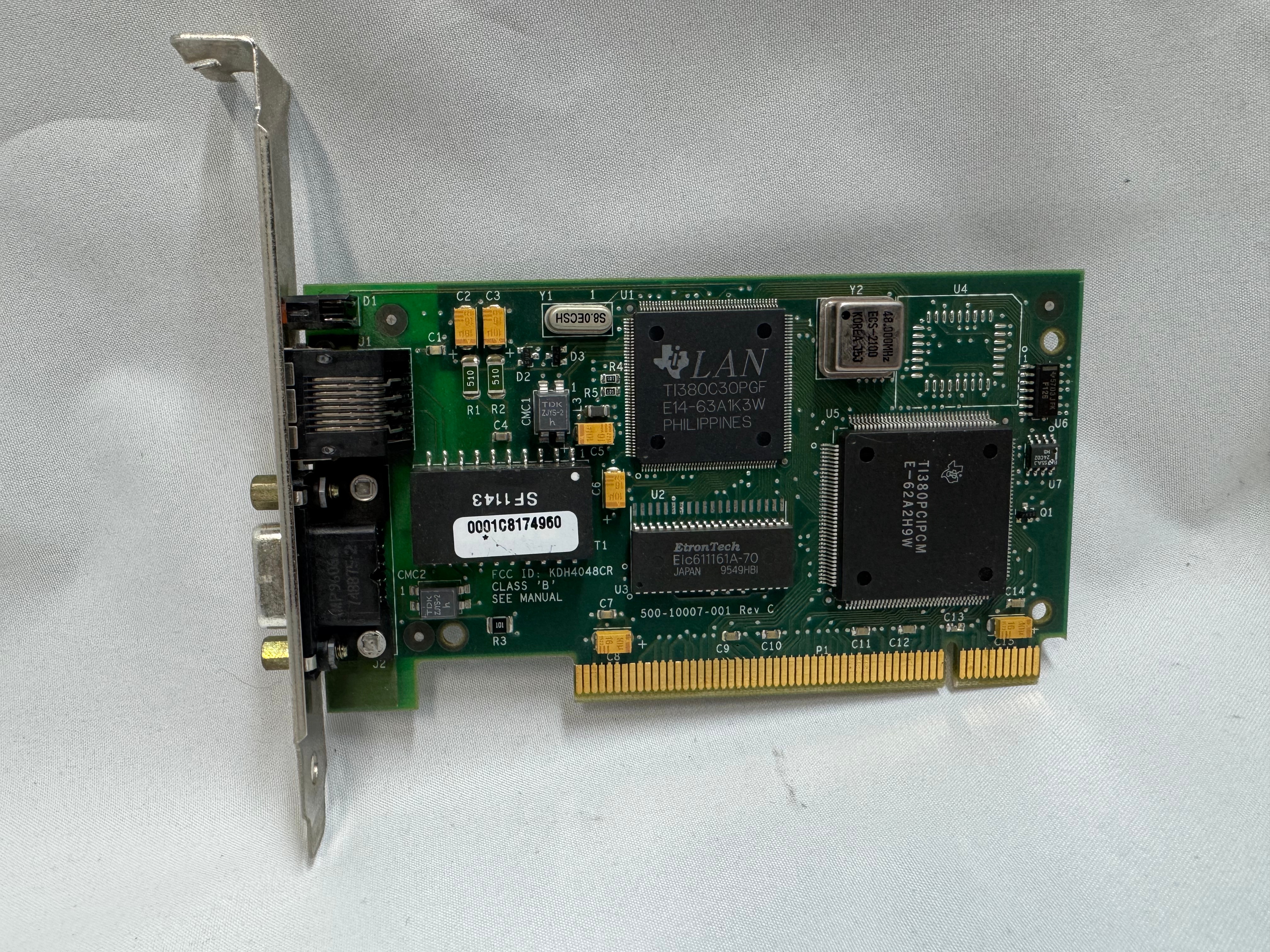
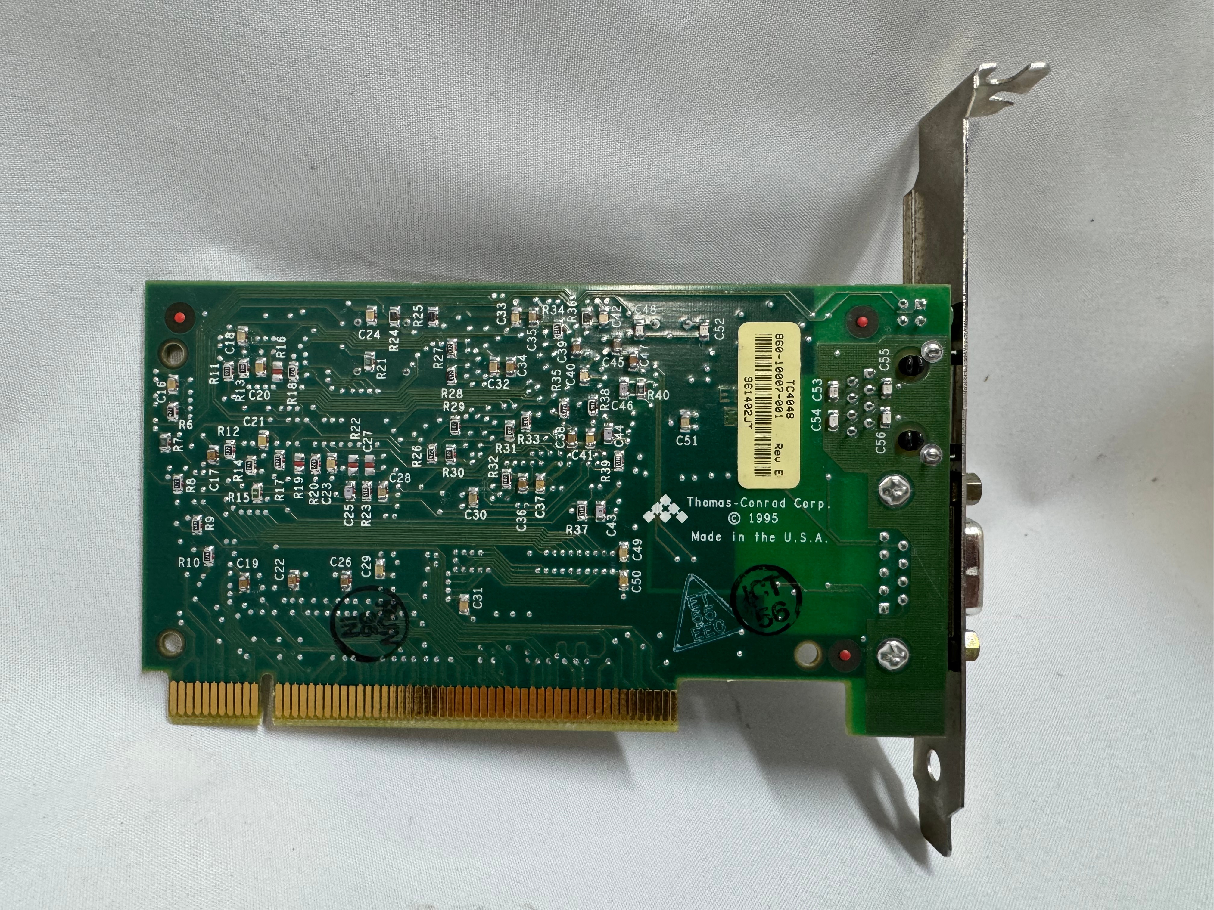
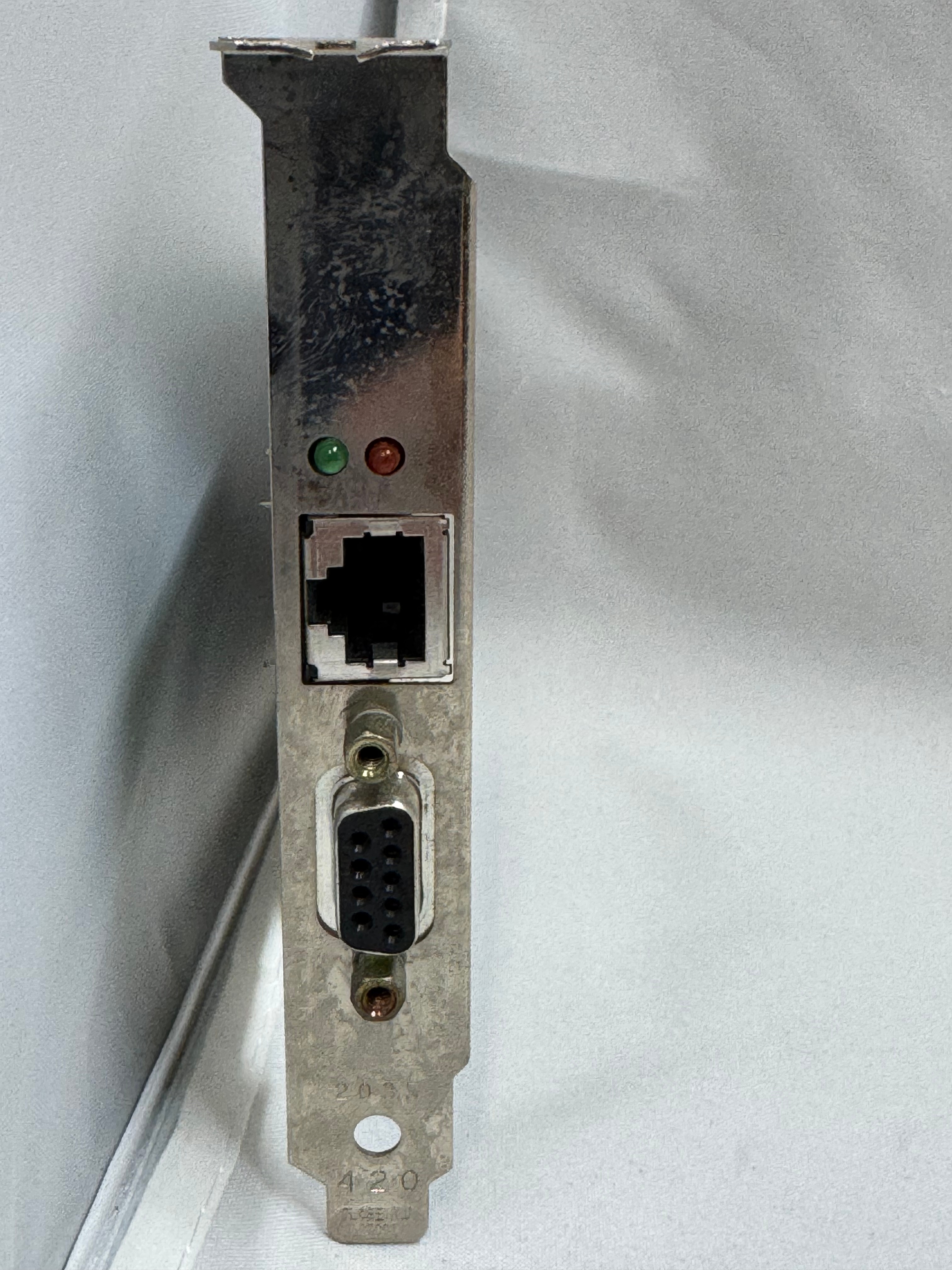
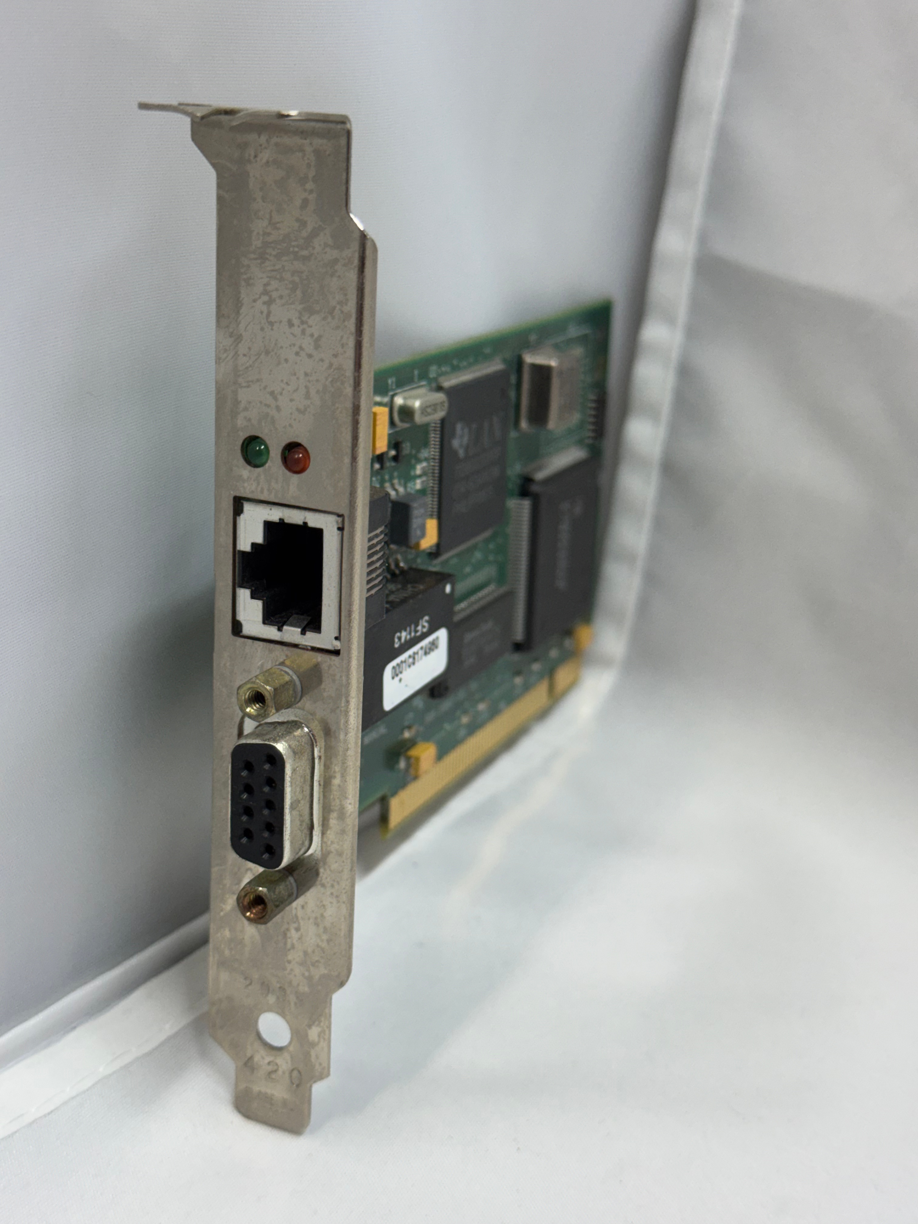
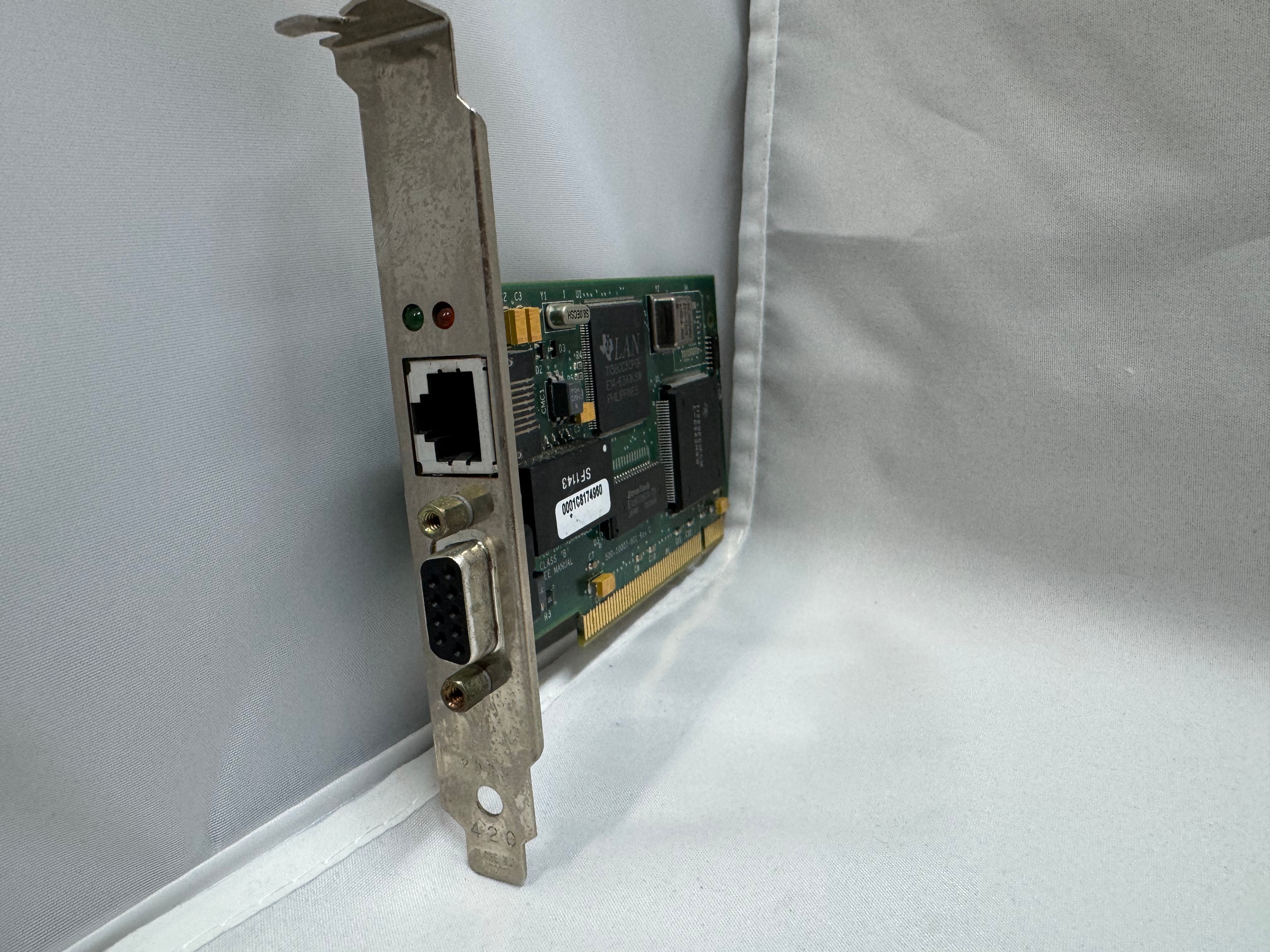
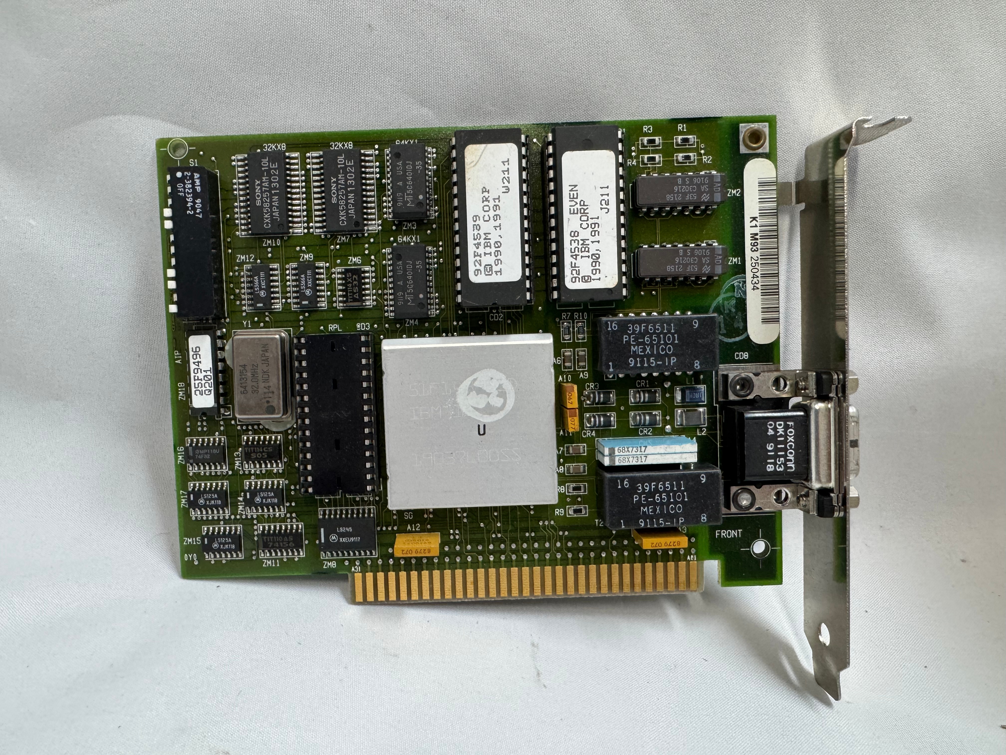
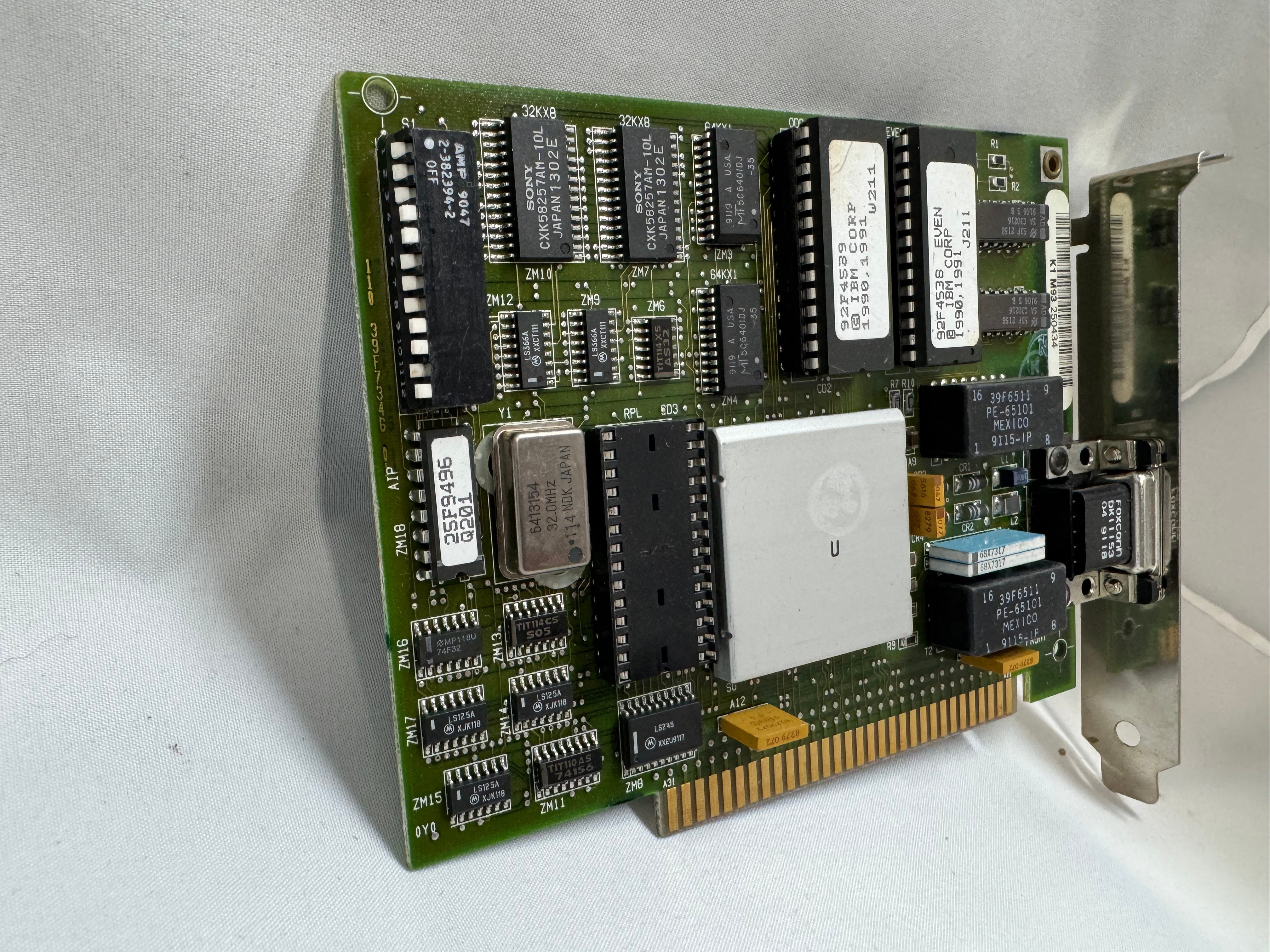
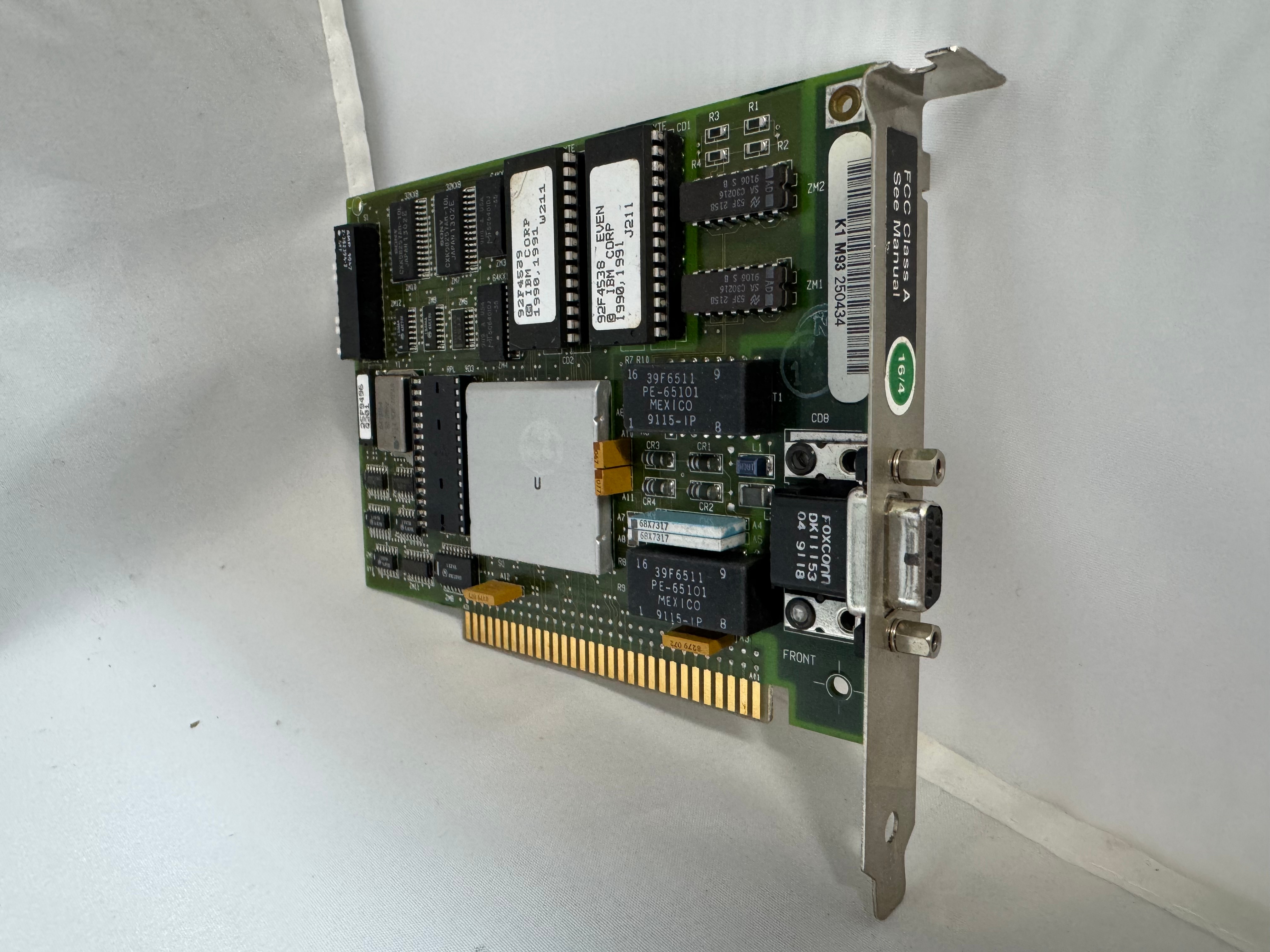
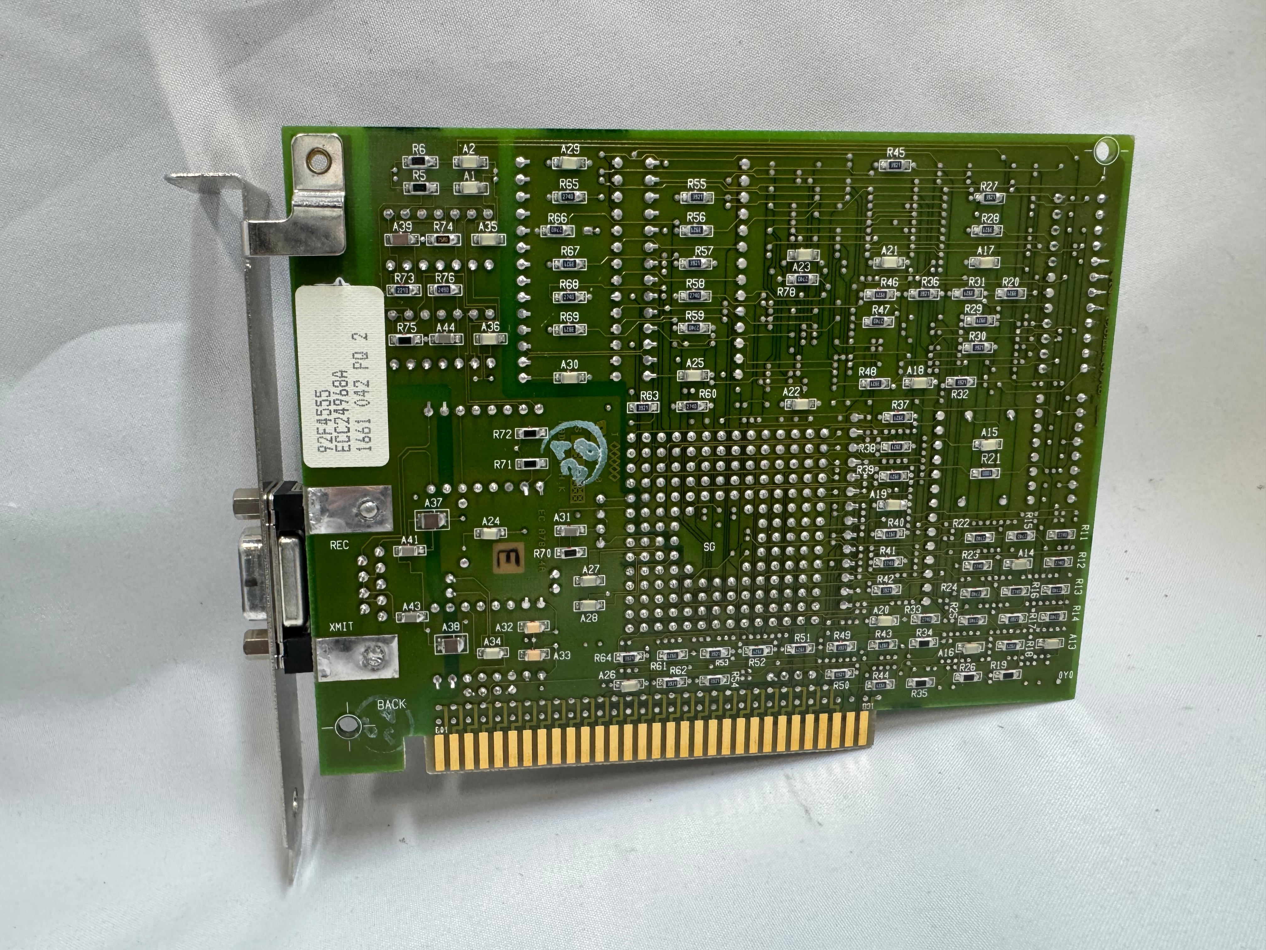
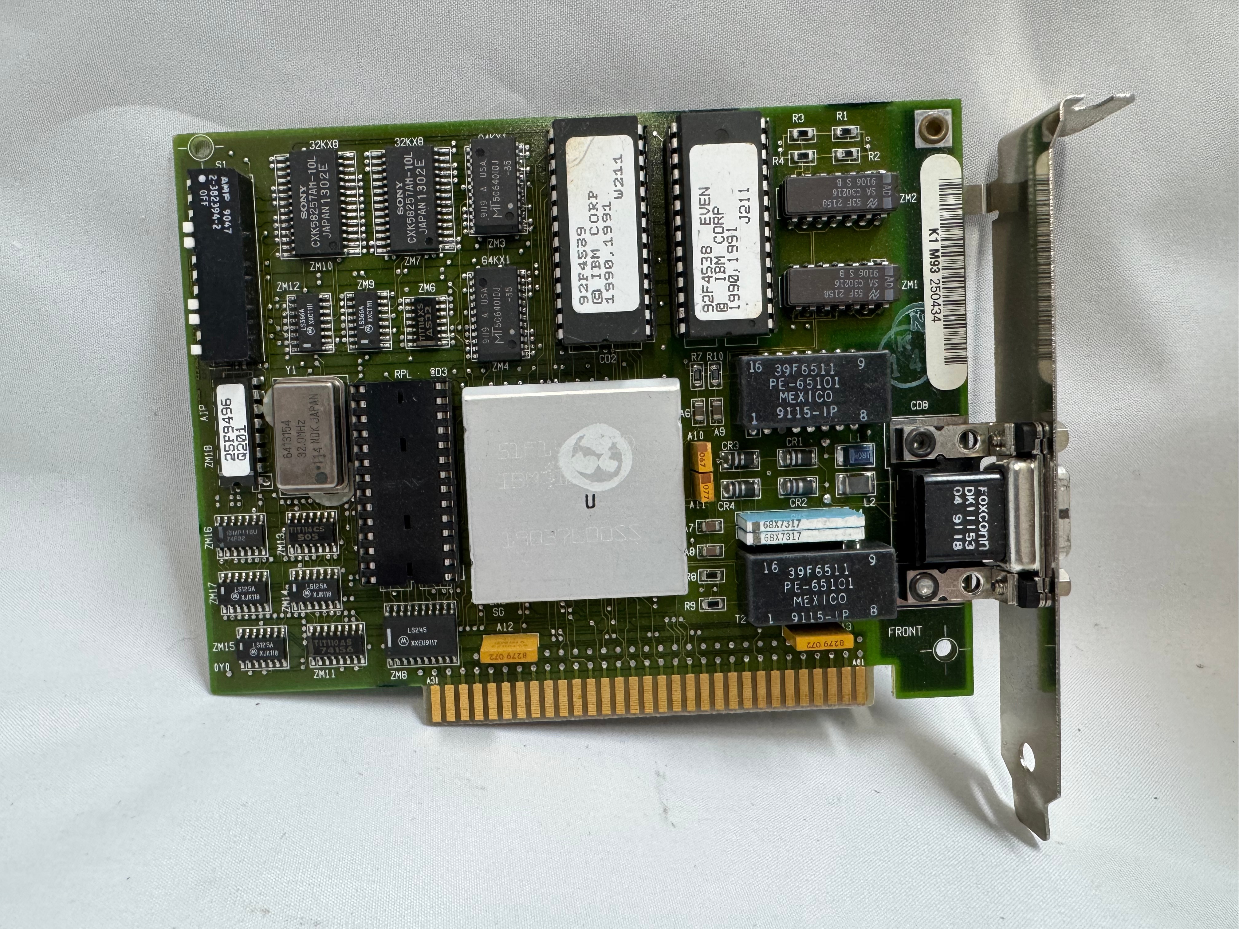
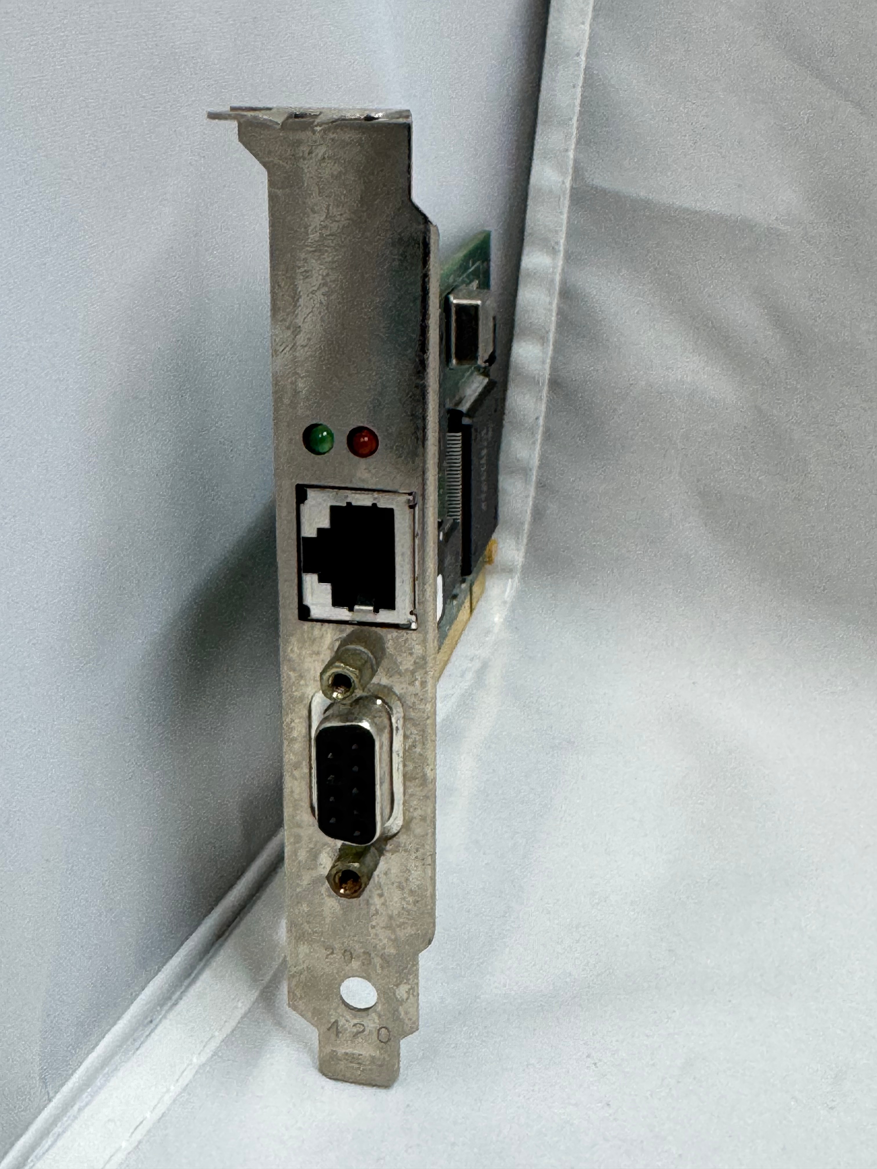
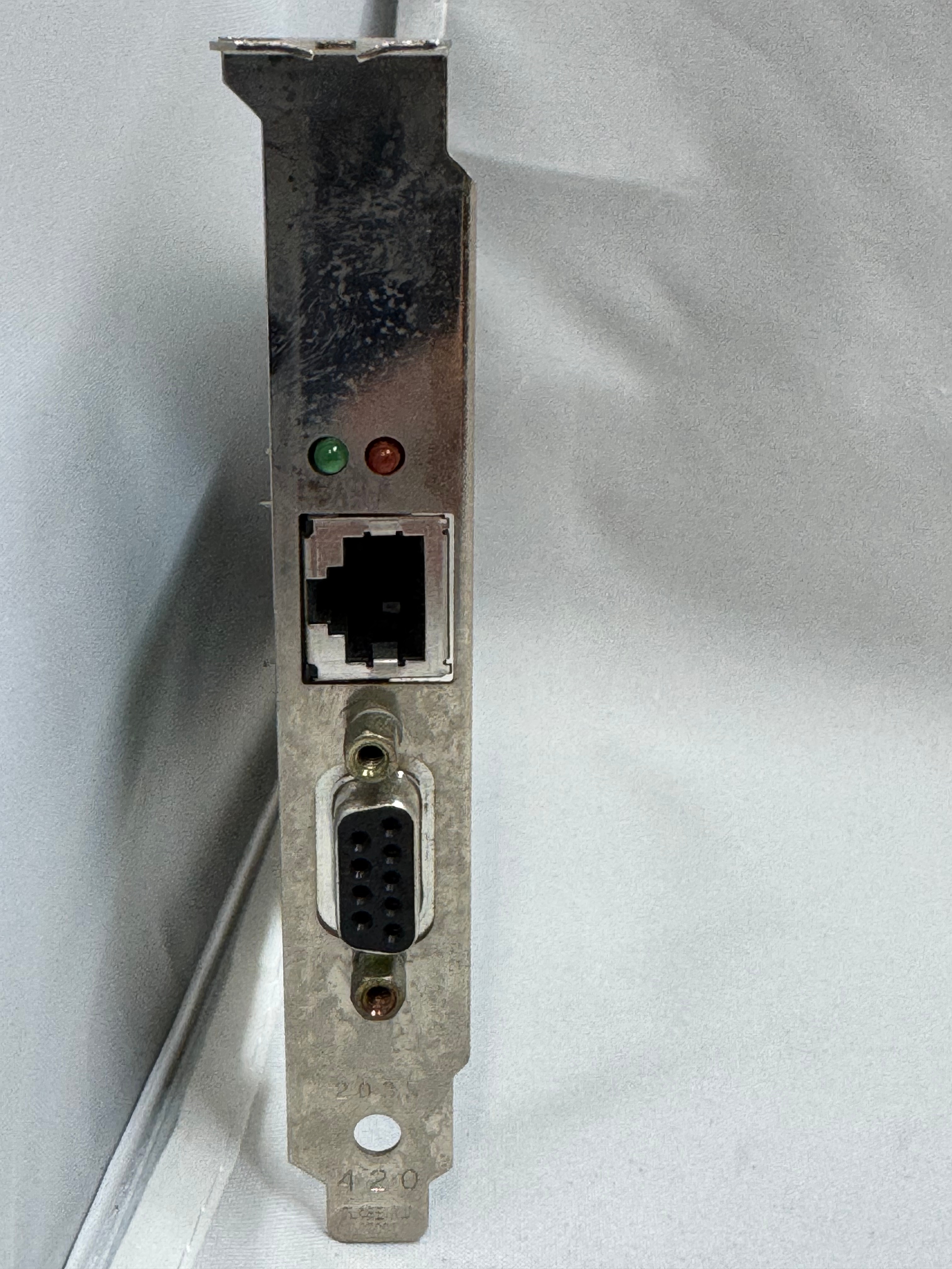
Last, but not least, I got a Thomas Conrad PCI Token Ring card for the system. It has 10/100Mb ethernet on the motherboard and in a breakout slot. But for the true retro rack road warrior, I needed the Token Ring to go with the rest of my Token Ring gear. There was one downside to this card, the same issue others have mentioned with Token Ring cards… The driver attempts to join the ring when the system boots; if it can’t, you get a 30-second or so delay, then an error message. Every. Boot. But that’s the price to be awesome and have Token Ring.
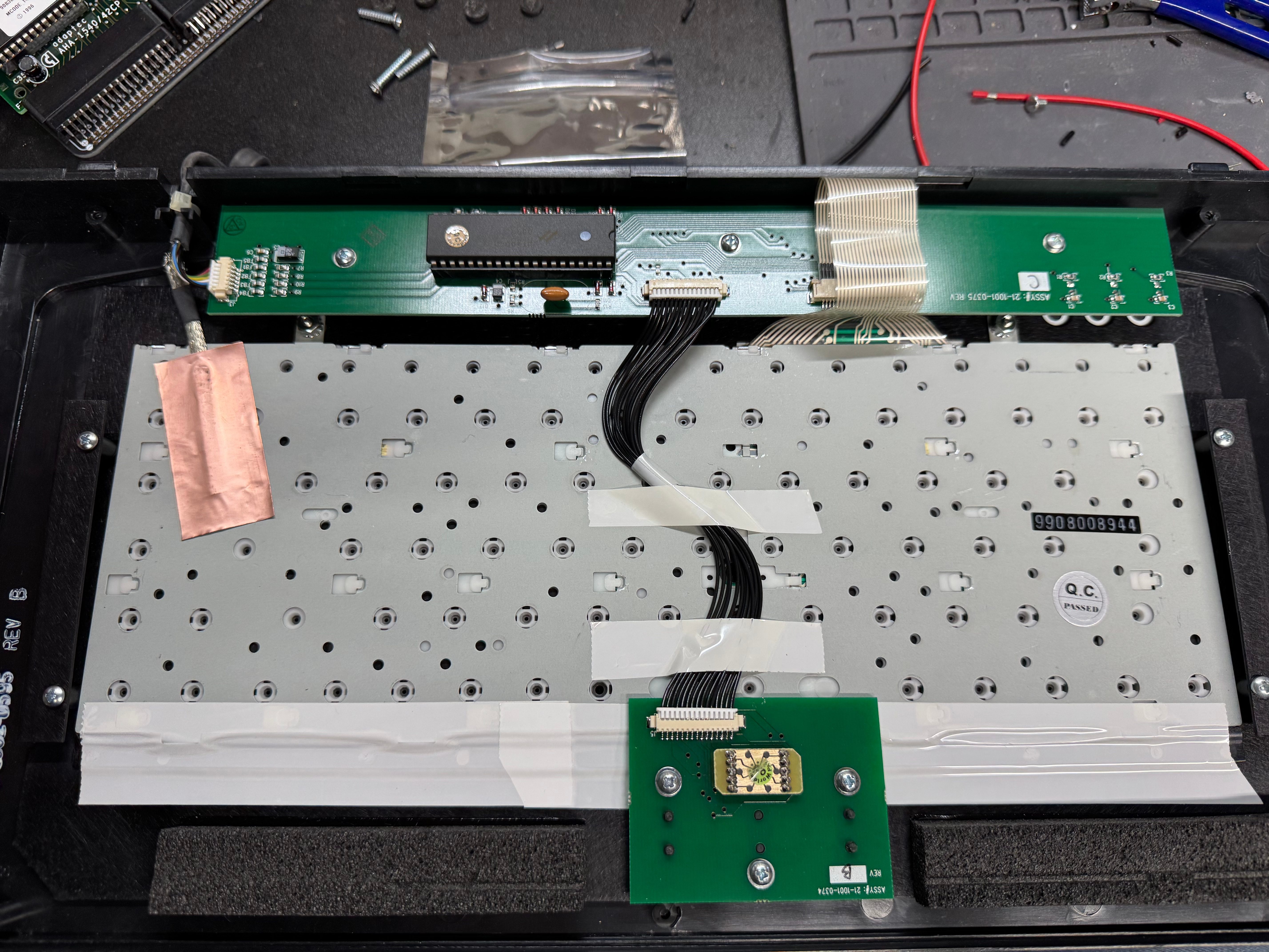
I had been using the system for a little while, and the keyboard had some sticking keys, so I took it apart and gave it a good cleaning. I think it still needs some work, but overall, it does what it needs to do. I can always use a USB keyboard now.
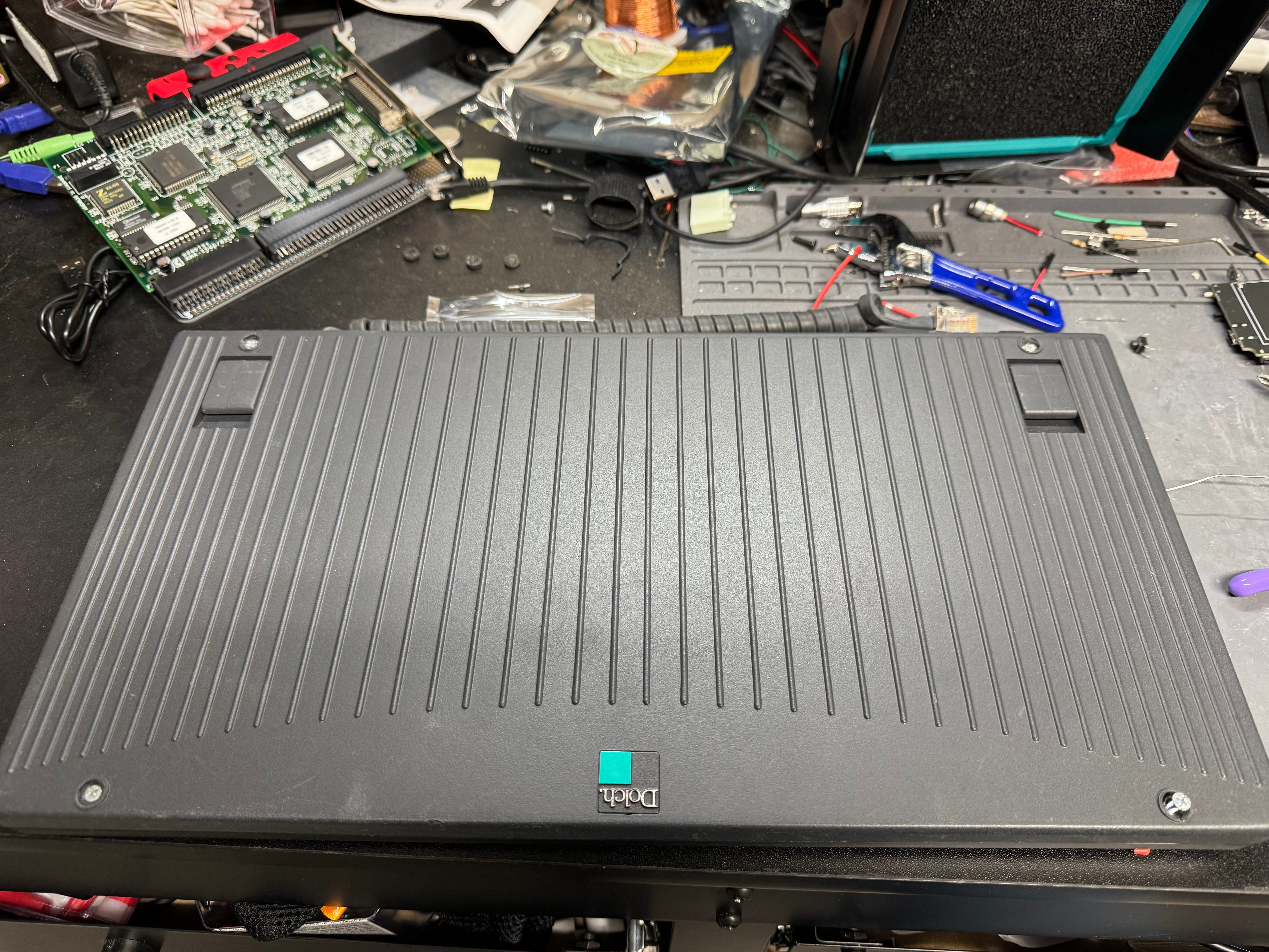
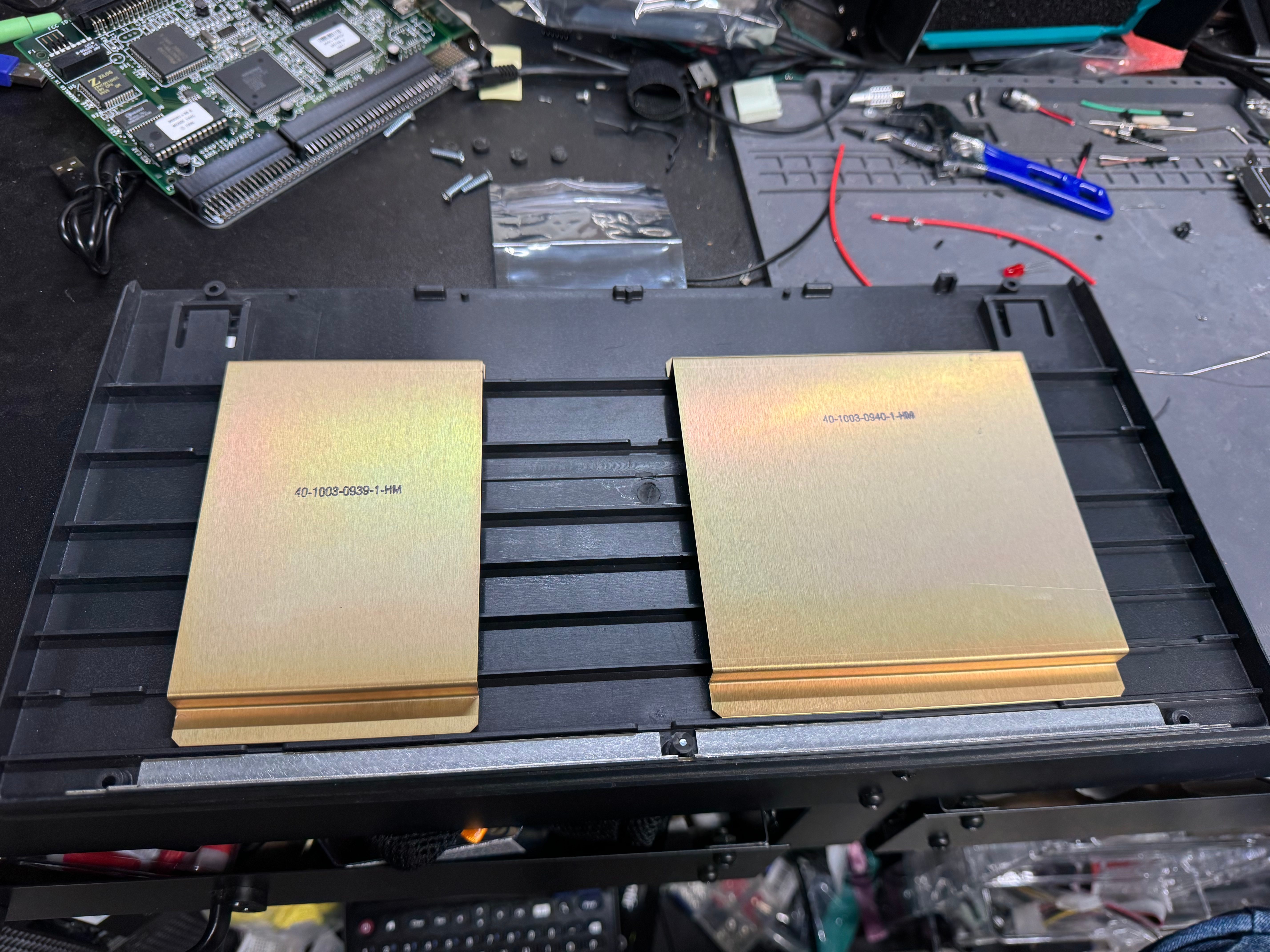
It’s a fun machine, I’m glad I got it. The nice part about portable systems is I can fold it up and put it in the corner. It’s my new go-to retro system. When I want it, I just pick it up, plug in a power cable, and I am back in business. There are some outstanding items: the power supply hasn’t been serviced and could explode at some point, the motherboard capacitors are 30 years old, and the ISA slot won’t recognize cards. We are going to ignore those for now and play RollerCoaster Tycoon instead!
Homelab Token Ring

For the LAN Before Time, my retro rack, I wanted to mix the most diverse set of CPU/OS/Networking I could find. There are not a ton of networking standards out there, as Ethernet took over so quickly. One that has always interested me is Token Ring, IEEE 802.5 standard, mostly from IBM as a competitor to Ethernet. Token Ring went through many transitions in its time on the scene, from speed changes to connector changes, lasting from the mid 1980s through the 1990s.

Connectors

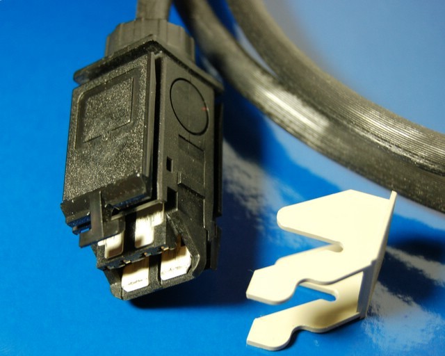
Photo creative commons from Wikipedia

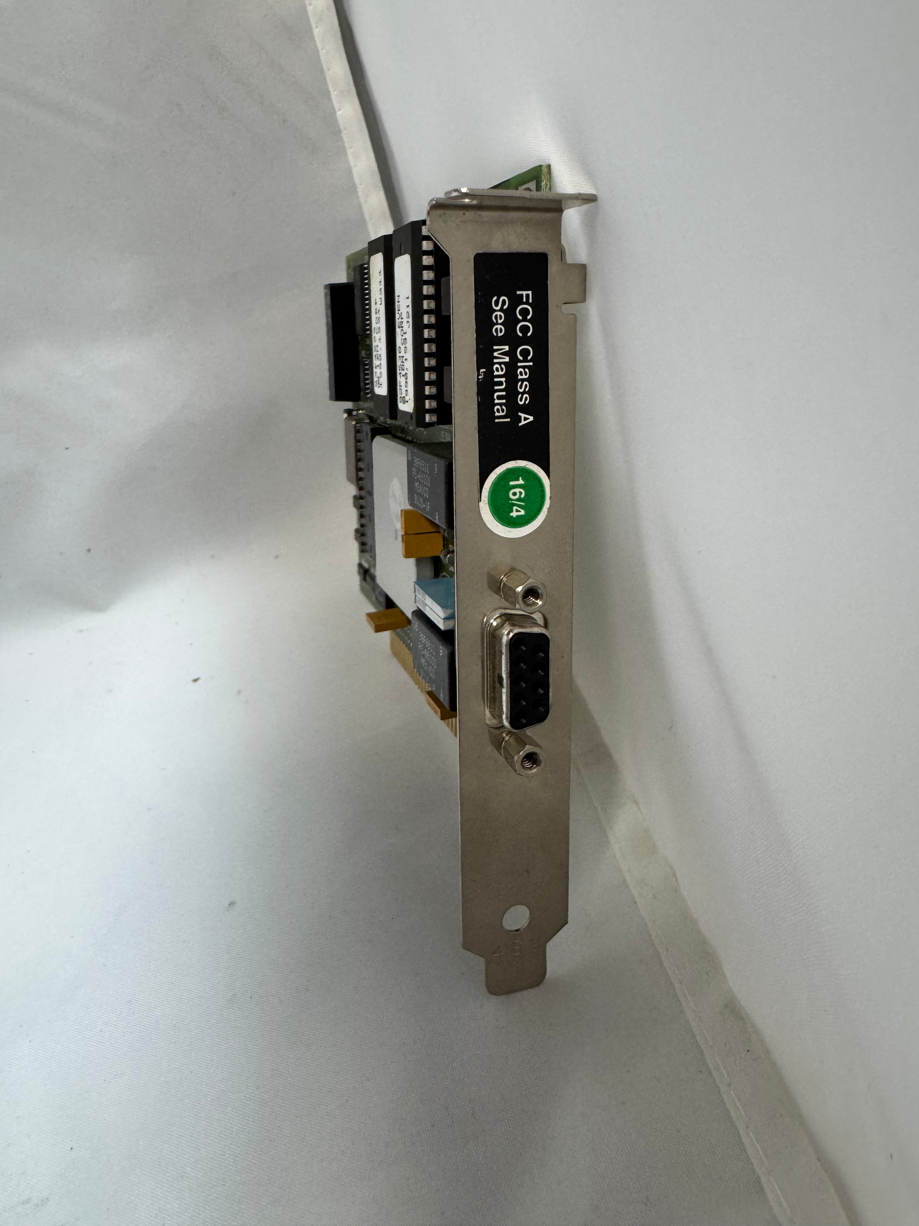
The protocol started at 4mb/s (megabits a second), with the computer having a DB9 connector going to a giant 4 pin plug.

Later 16mb/s was added. Most of the cards you will find are 4/16 cards.

The physical connector, and connection speed are independent, you can use either the DB9 or RJ45 connectors to run 4mb/s or 16mb/s.

The cards started in the ISA era and later continued into the PCI era. The connector also evolved to a standard RJ45. There were adapters to go between the older connectors and newer ones. Later cards would include both DB9 and RJ45 connectors. With RJ45, only the middle 4 pins were used, but in a straight through way, allowing normal Ethernet straight through cables to be used.

In the last updates to the protocol, 100mb/s Token Ring was added, but by the time that came out Ethernet had taken much of the market share. And finally in 2001 a 1000mb/s standard was created, but Wikipedia says no devices ever came out for it.

MAUs

Unlike Ethernet, Token Ring cannot connect two computers directly. You need to go through a Media Access Unit, or MAU. These units control ports going in and out of the ring. They can be thought of like an Ethernet hub or switch. The Token Ring itself also needs a terminator on it. Later models contained internal terminators if put into a specific mode. There are MAUs with the old large IBM connector, and there are newer ones with RJ45. There were adapters between any of these connection types for networks in transition.

My MAU Journey

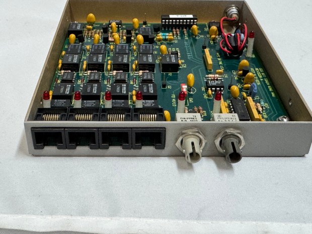
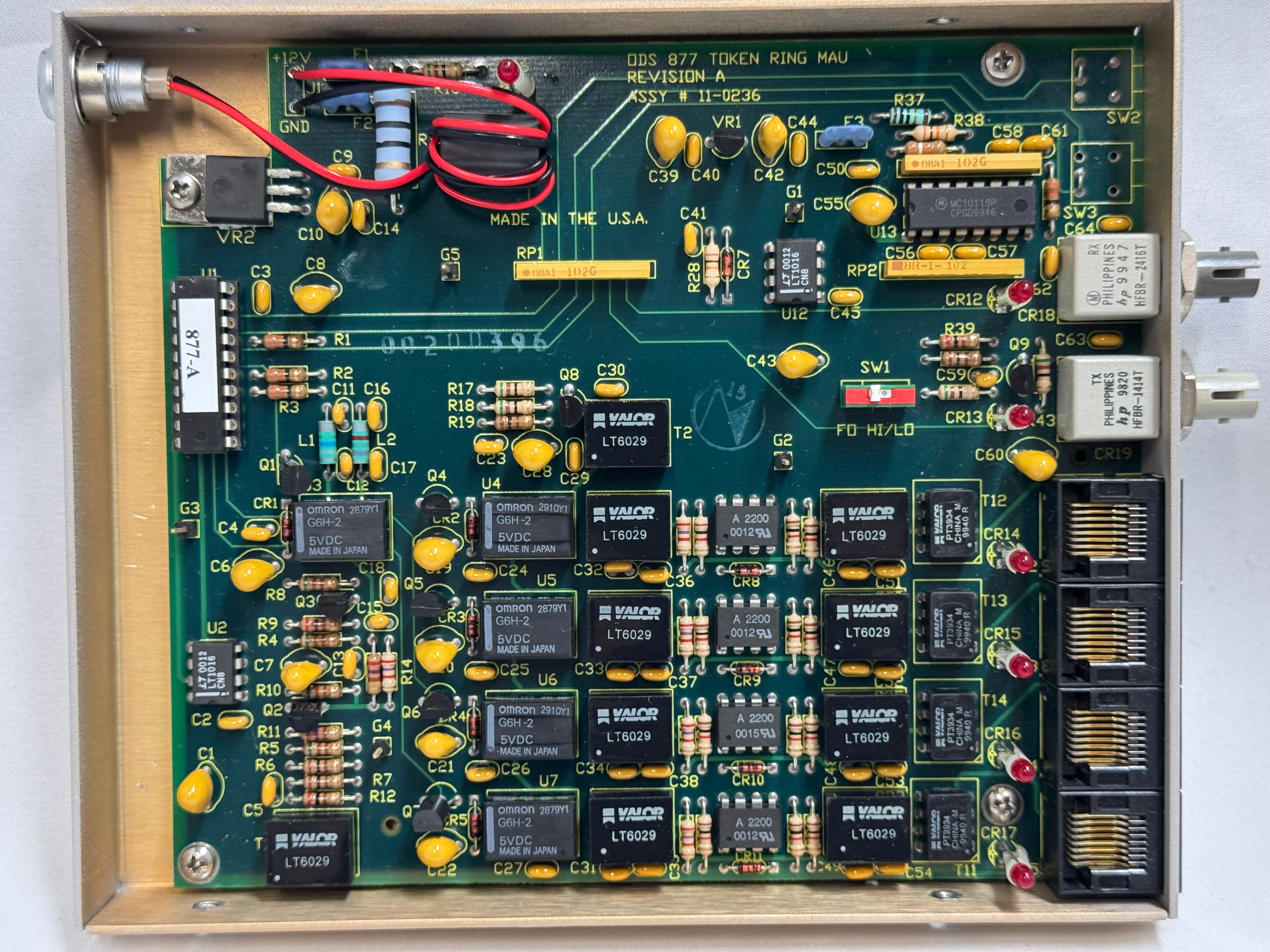
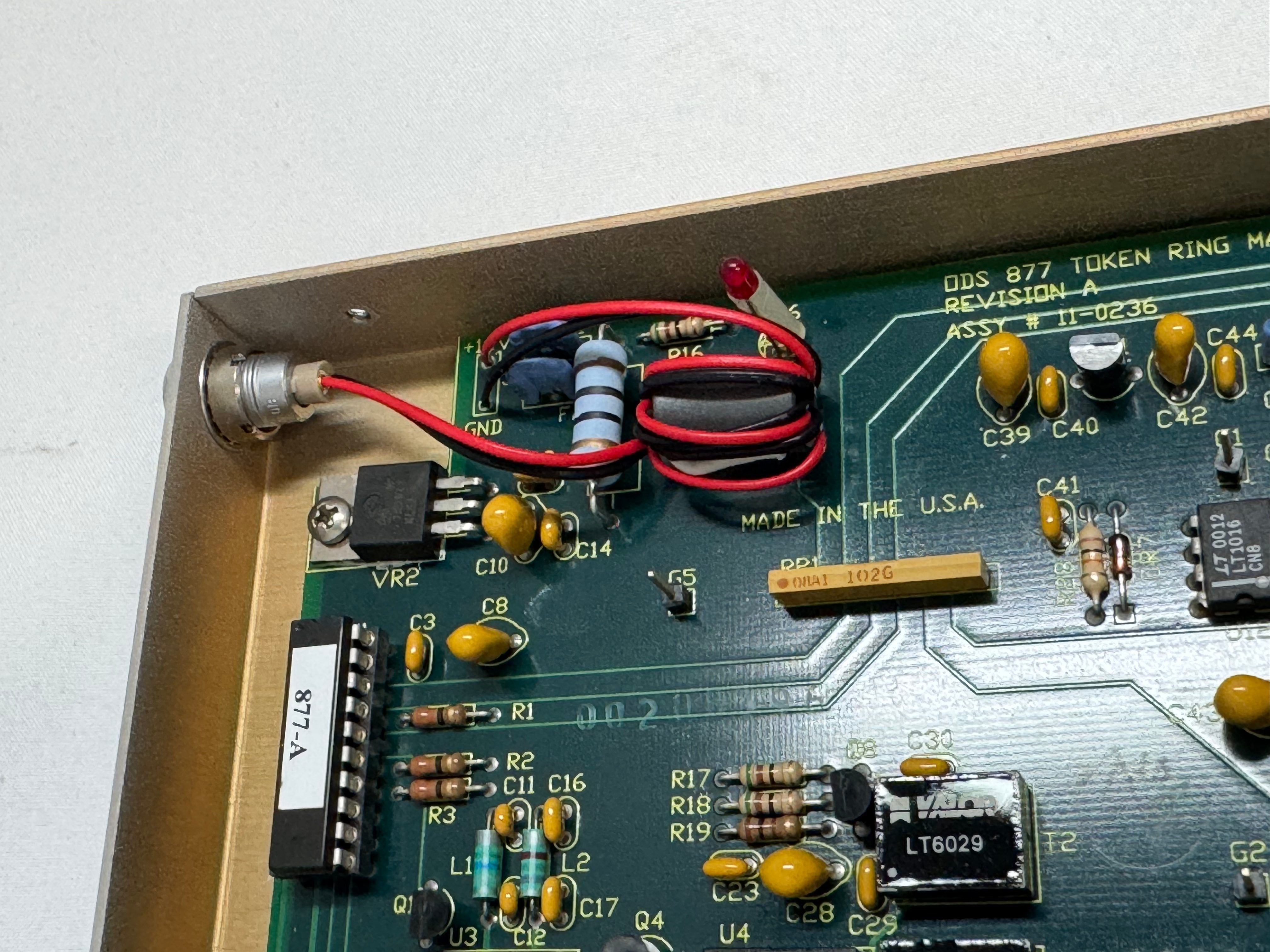
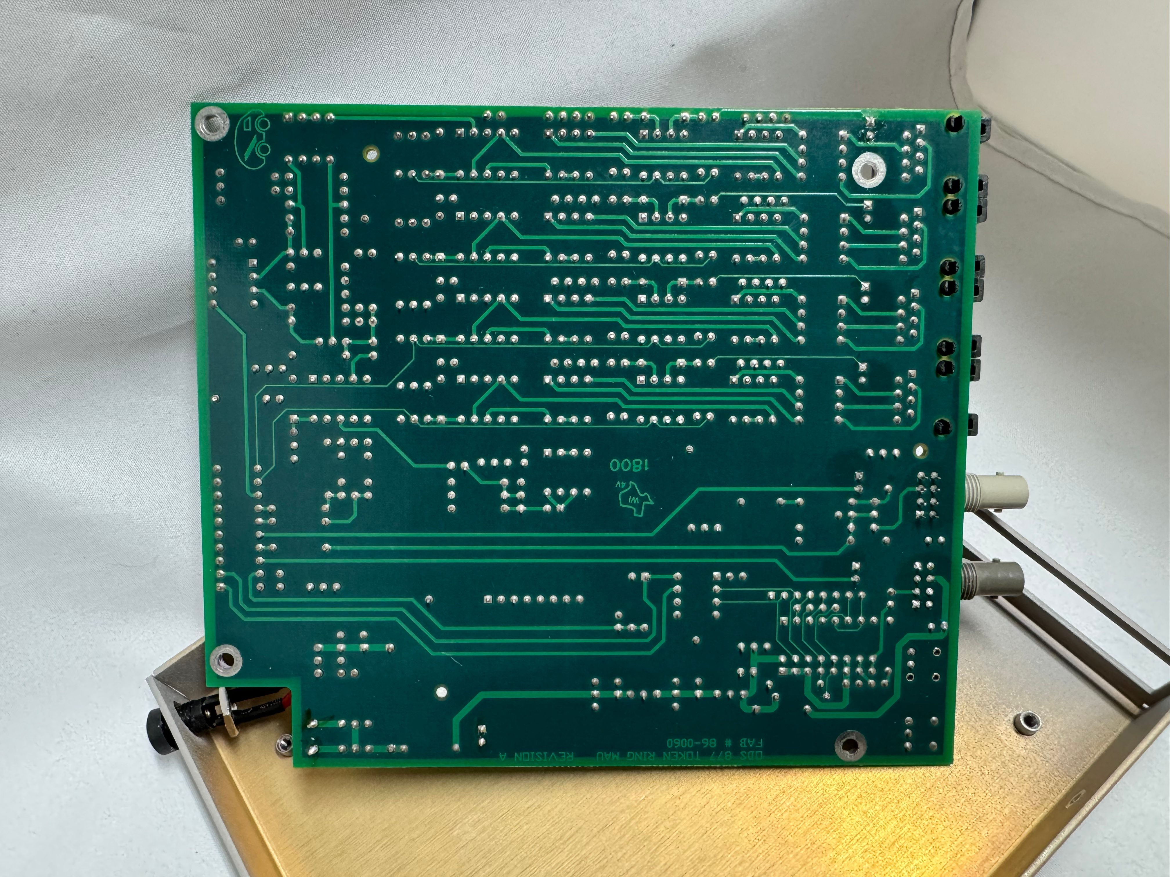
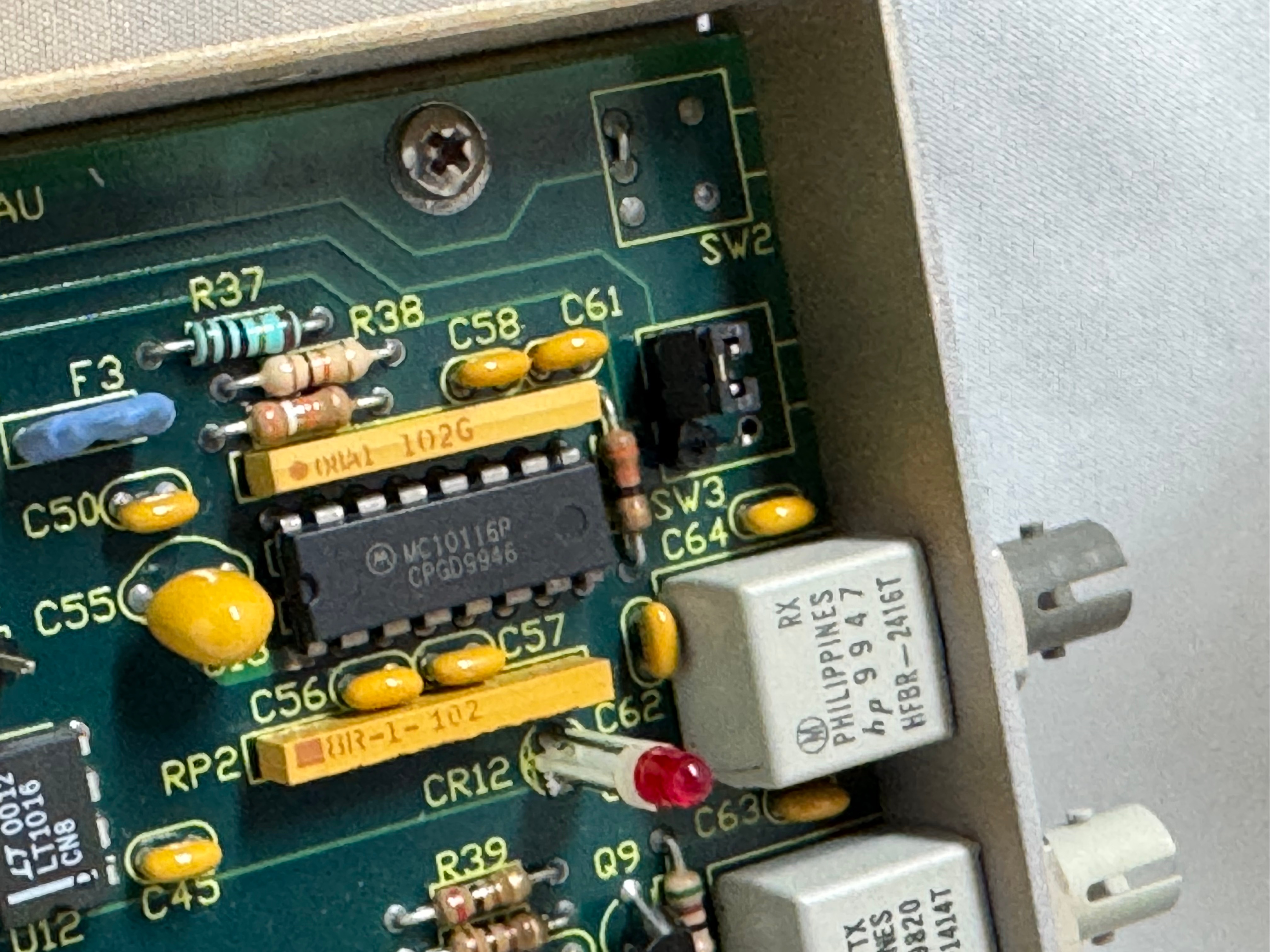
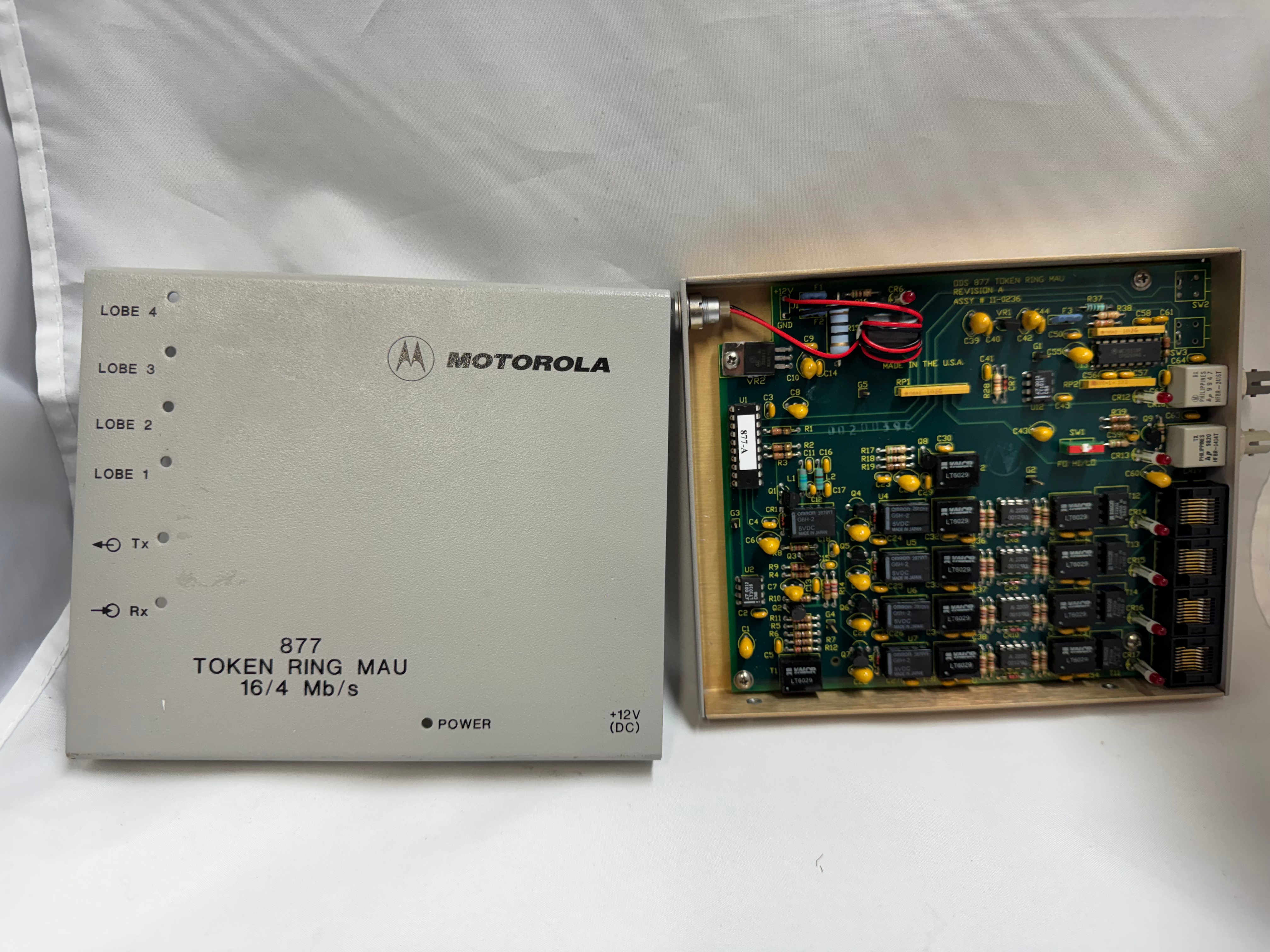
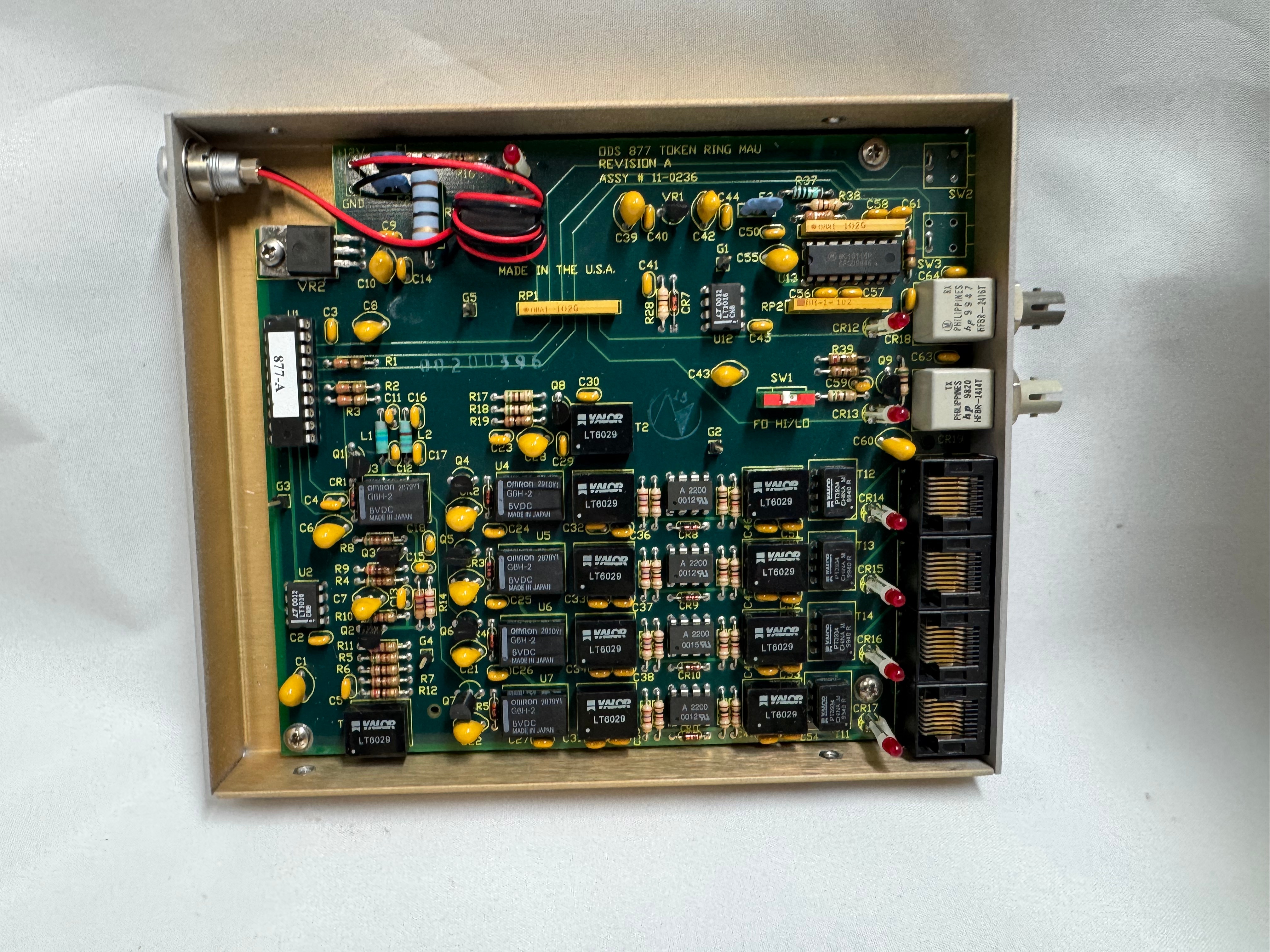
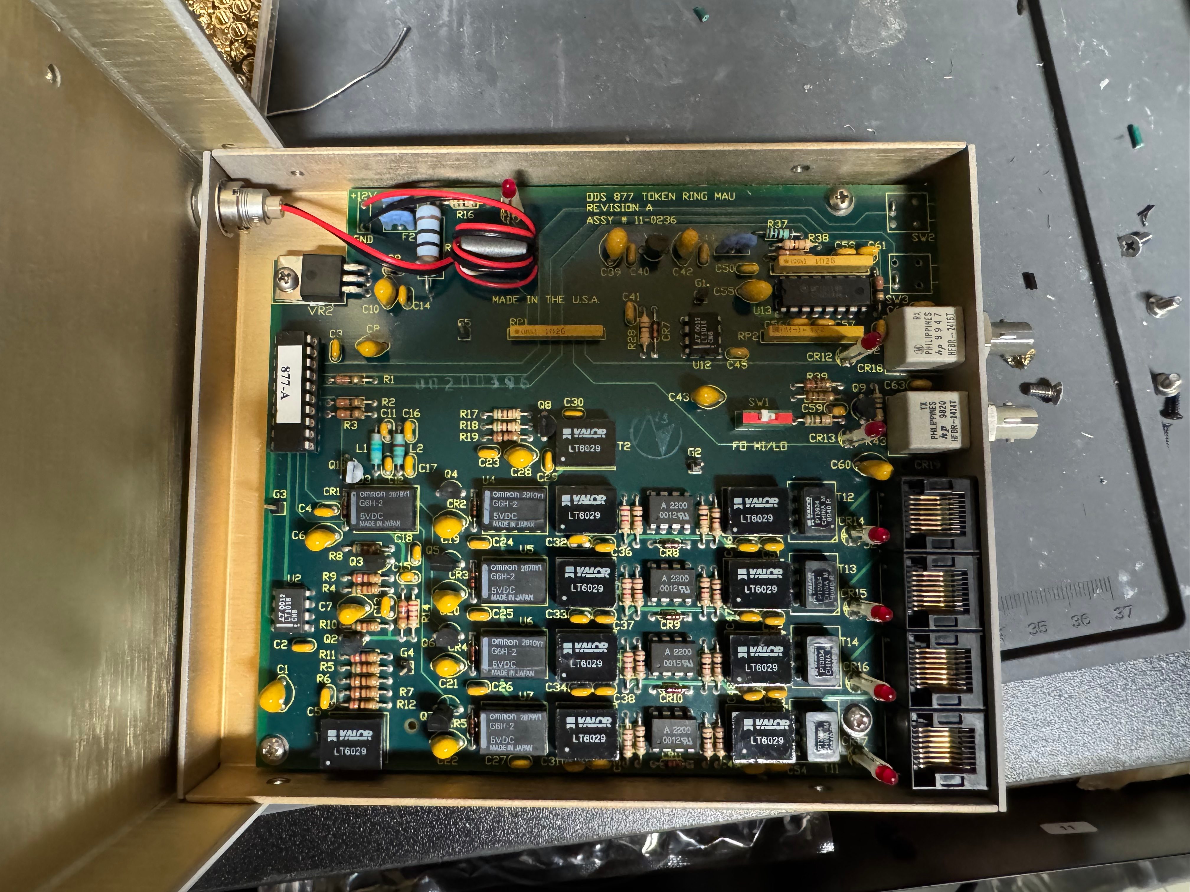
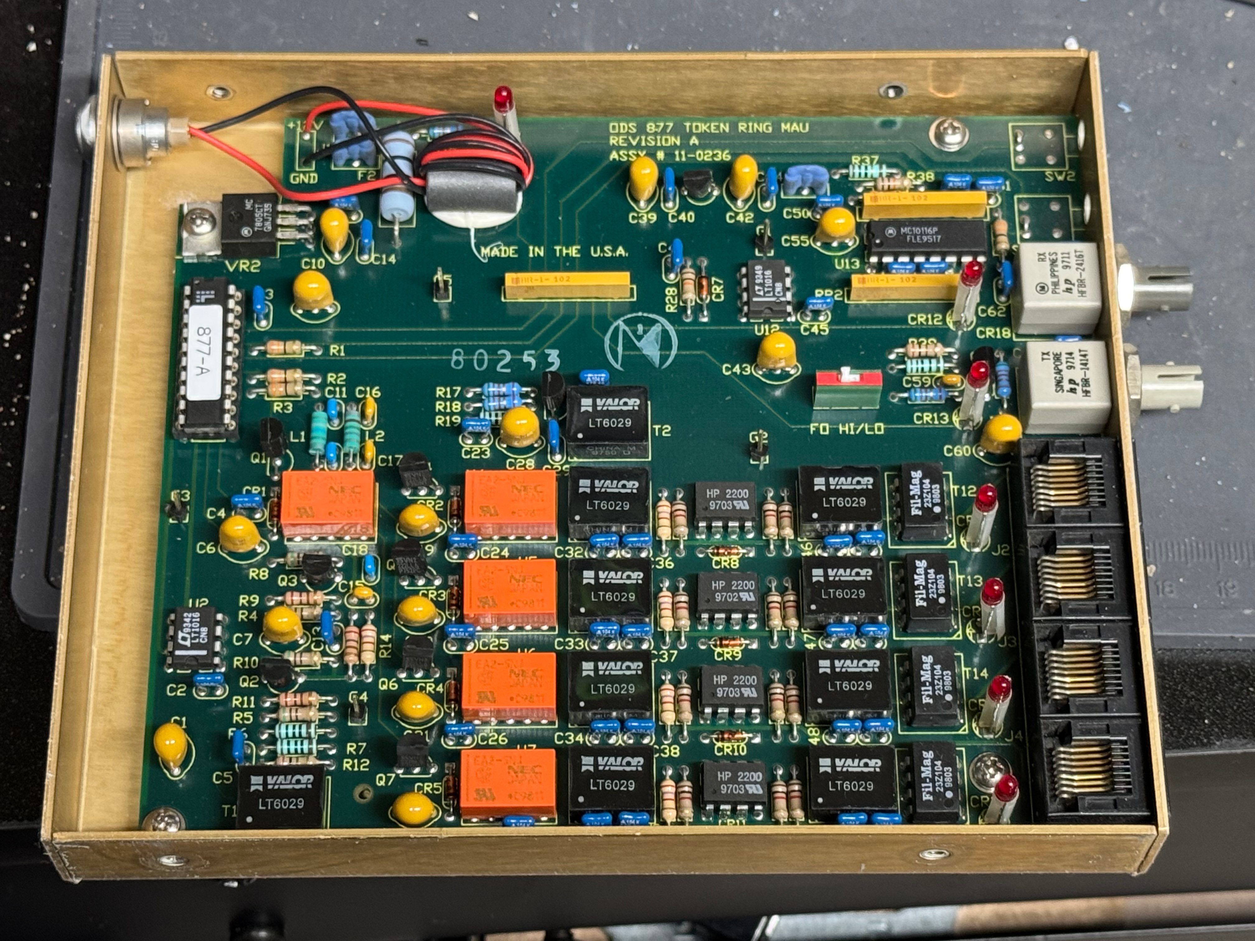
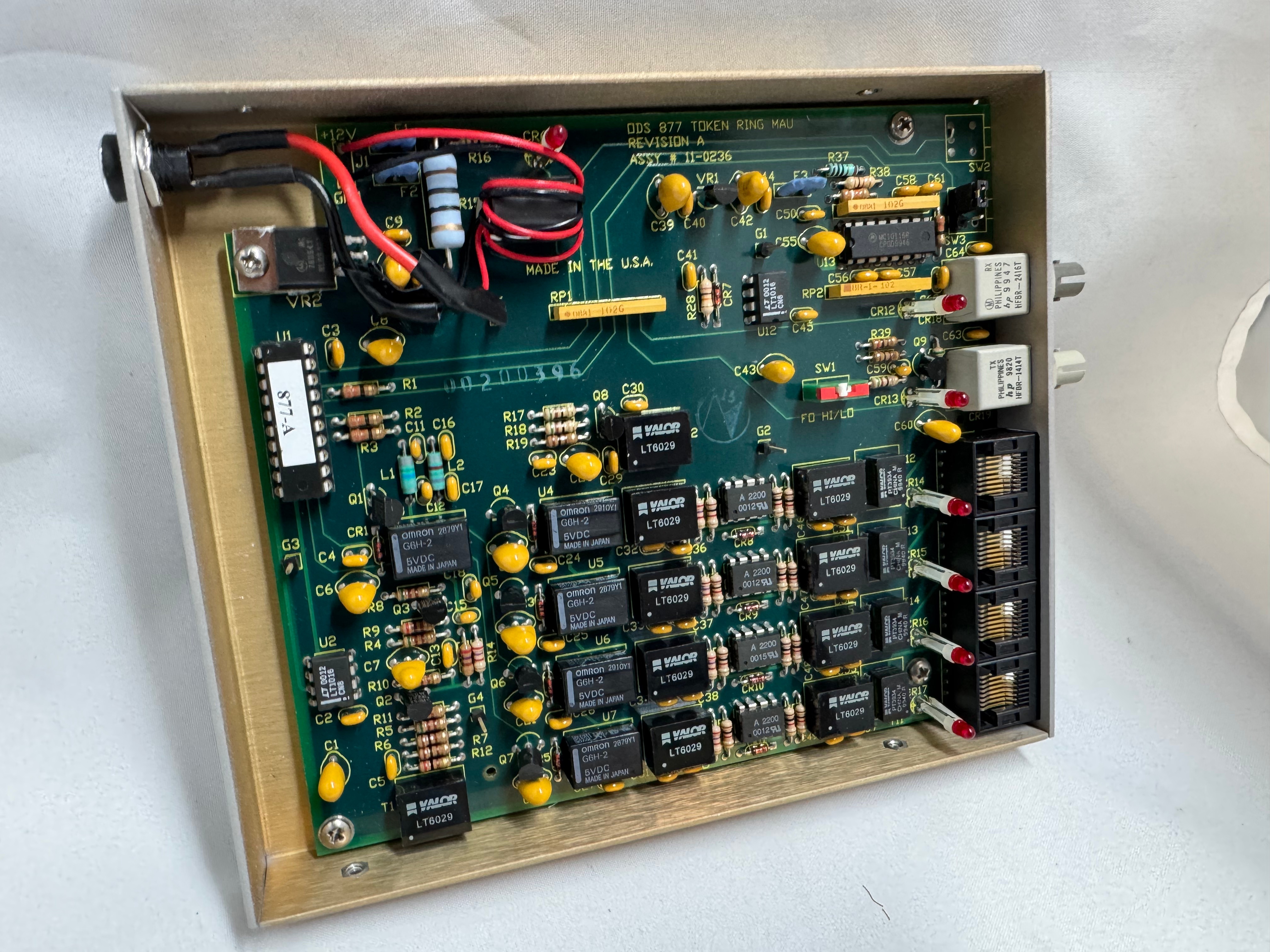
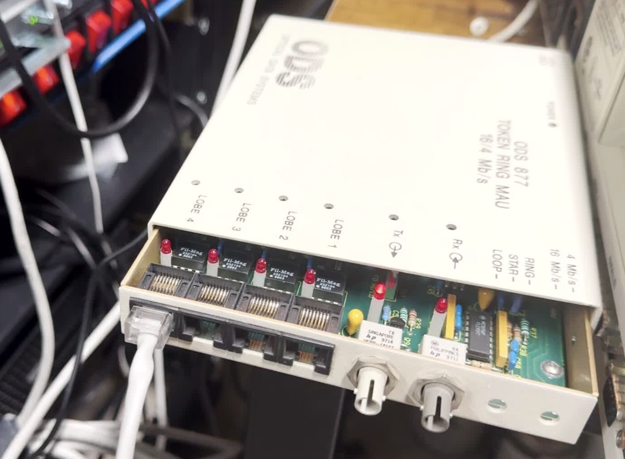
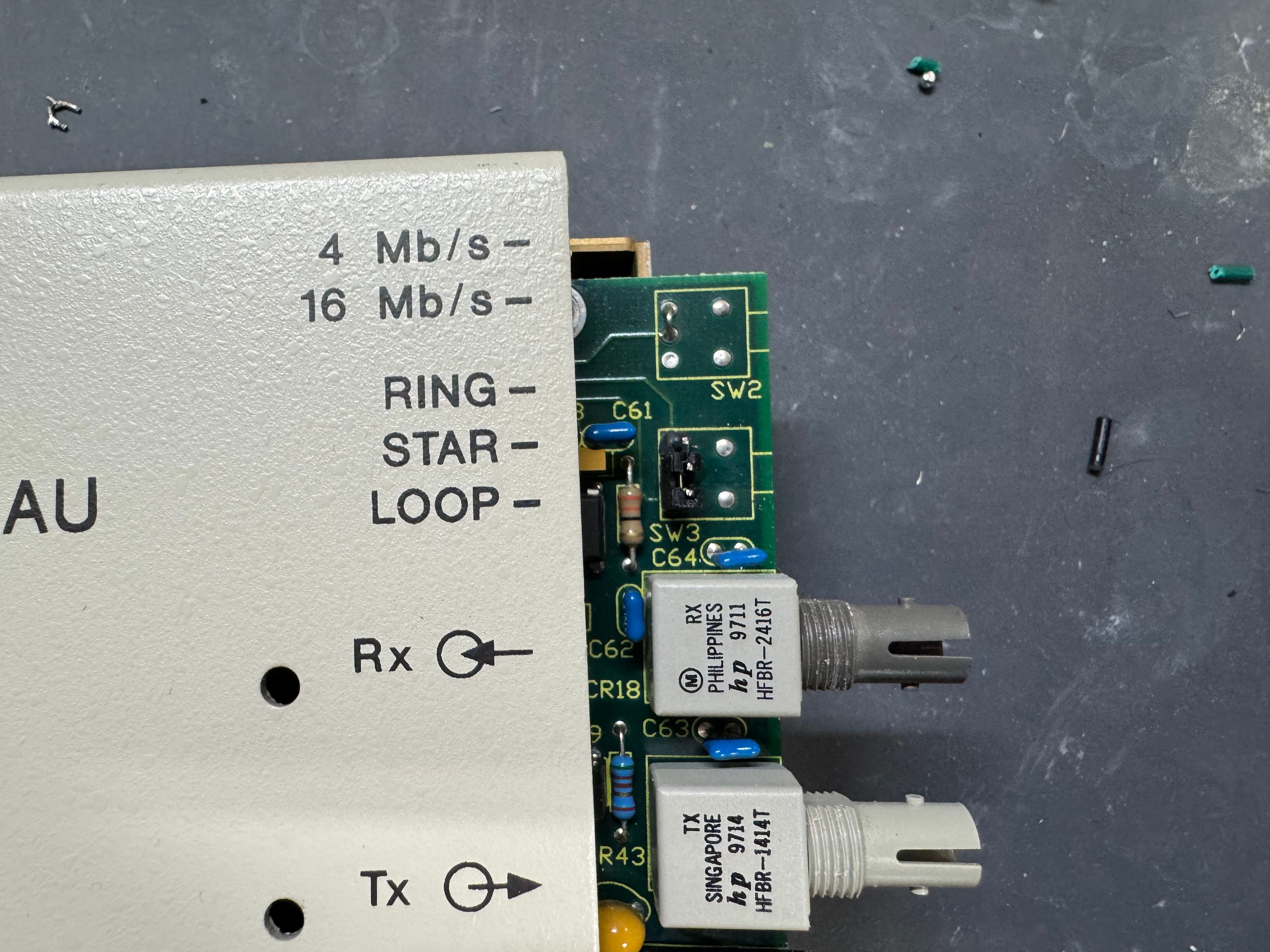
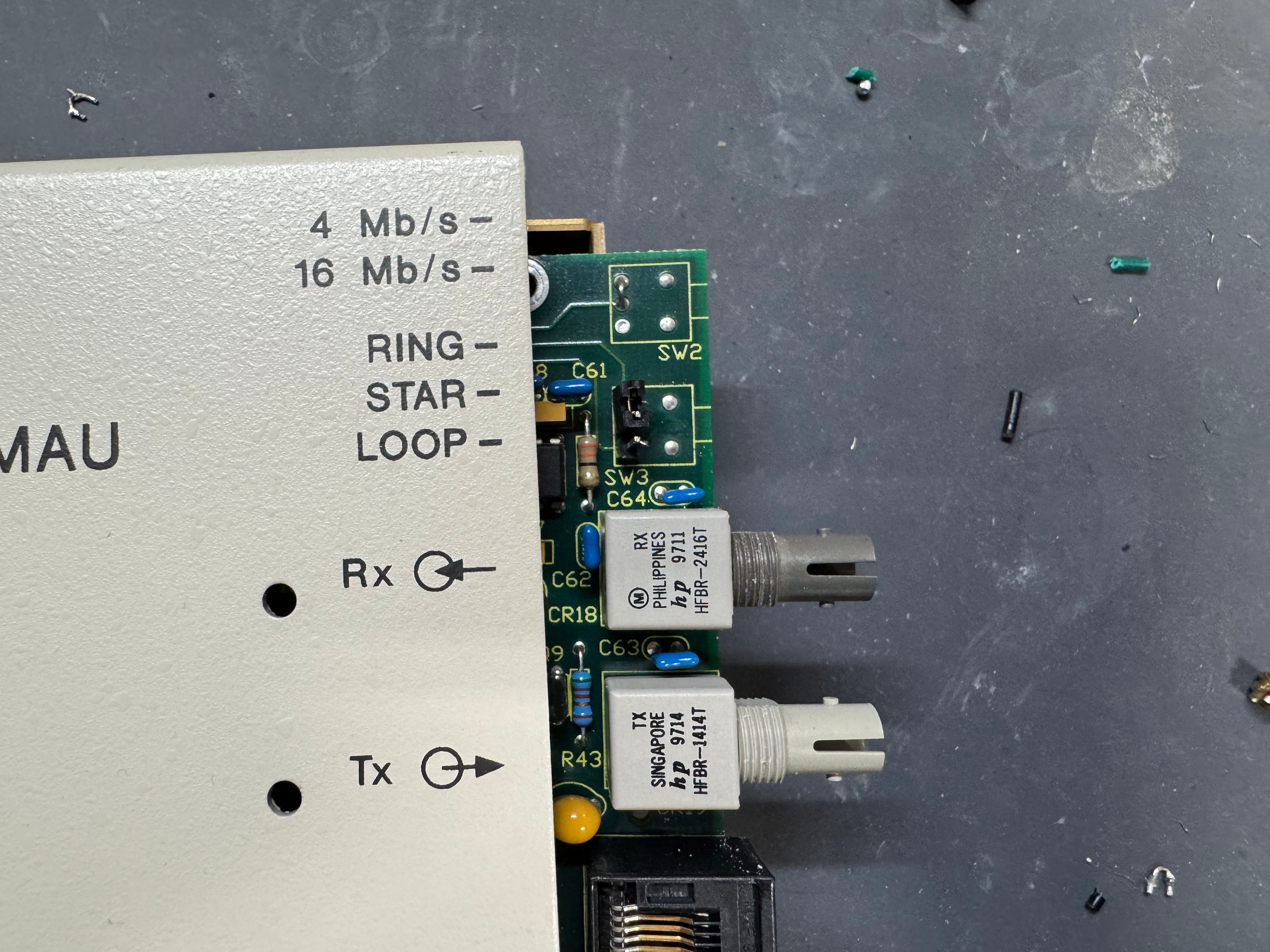
I picked up 2 of the same model MAU. ODS/Motorola 877. These are great units after some hardware tweaks and I would recommend them. While they are the same model, and same firmware revision, Motorola bought the company ODS (Optical Data Systems) which made them. The first one I got has ODS branding and a spot for two switches to control the mode and speed of the MAU. The second one is Motorola branded on the case, but not the board, and is missing the cut out in the case for switches.

From what I can learn with working on it, looking at documentation for other MAUs, and Claude; the device can work in three modes:

  • RING: Normal Token Ring operation, requires external RI/RO loopback cable to close the ring, use this when daisy-chaining multiple MAUs together, all active lobe ports are part of the ring.
  • STAR: Each port operates independently (not a true ring), used for certain troubleshooting or special configurations.
  • LOOP: Internally connects Ring In to Ring Out, self-terminates the ring without external cables, perfect for a single standalone MAU.

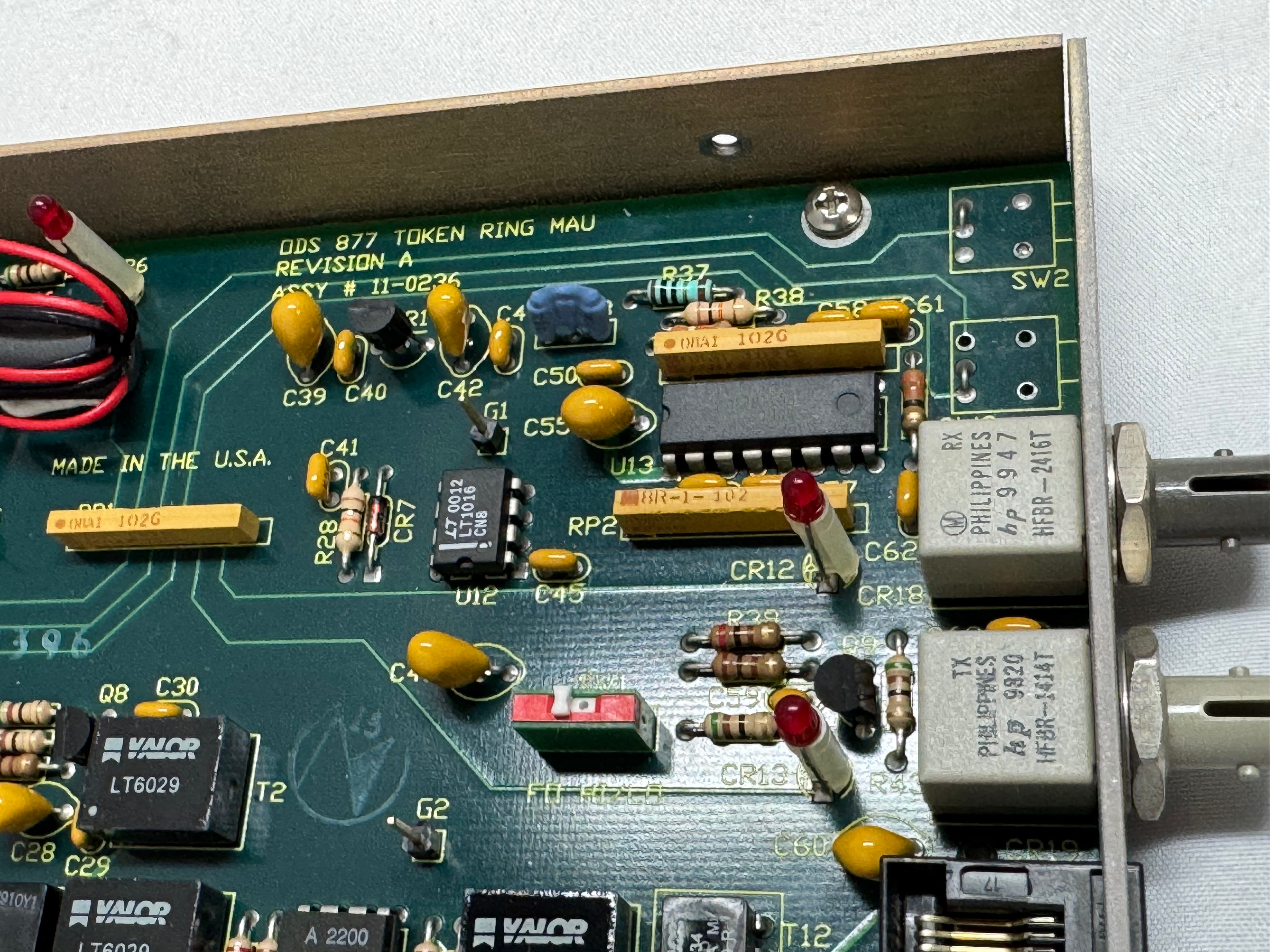
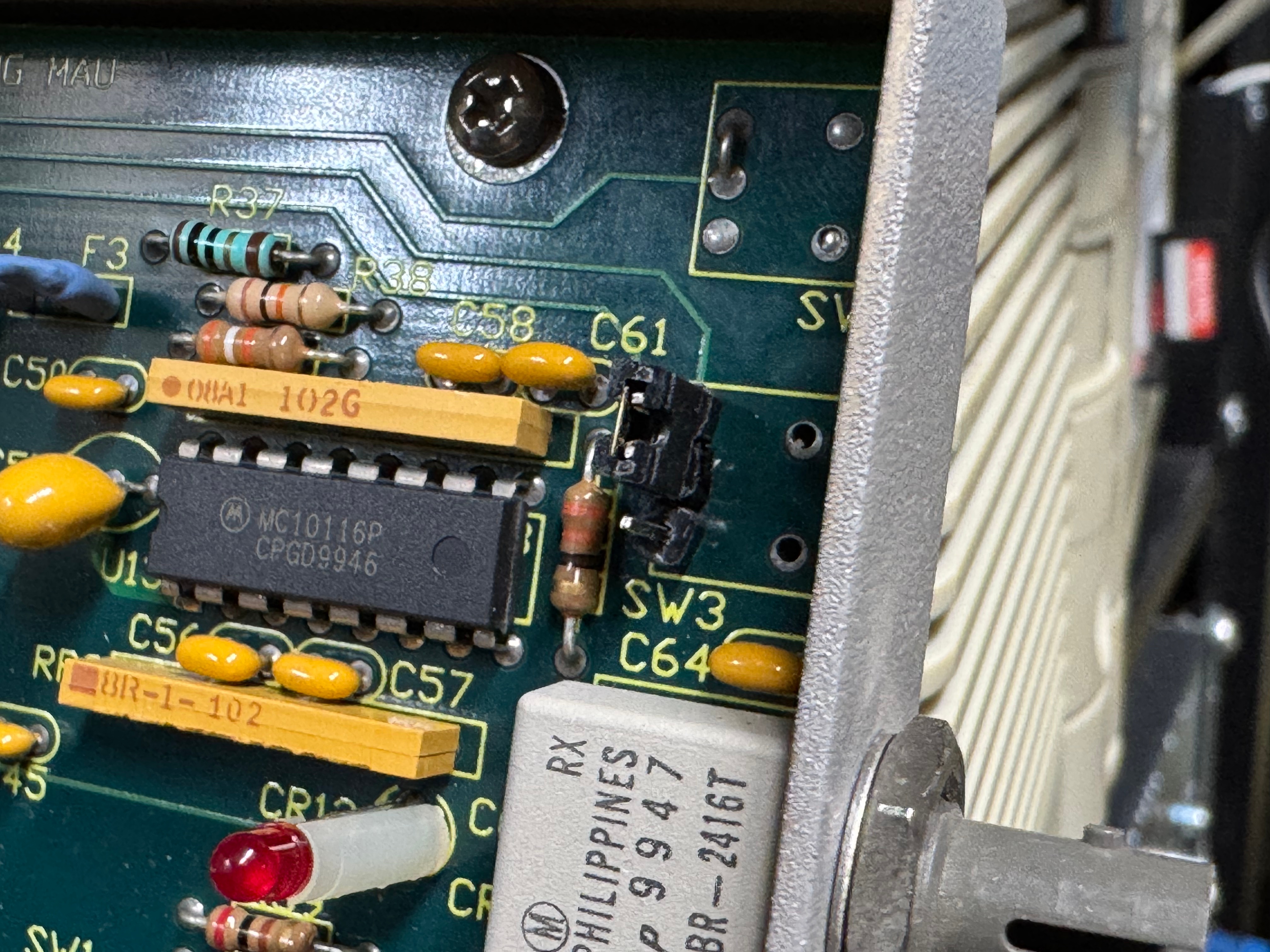
The MAUs were designed to have a switch to go between modes. Neither of mine did, both had a physical soldered in jumper setting their mode. The Motorola one didn’t have a hole in the case for a switch to exist, but the PCB is the same. I removed the soldered jumper and replaced it with a standard PC jumper pin, that way I could easily change it when I wanted to. In the end I will leave them both in LOOP mode most of the time, that has internal termination and is used for simple 4 port usage. Bridging the top and middle pin put it into LOOP mode, which is what I needed. Before that it was in RING without termination; each device would join the ring for 10 or so seconds, not hear anything else on the ring, and then disconnect. This MAU appears to be able to automatically go between 4mb/s and 16mb/s mode and I never moved the speed jumper.

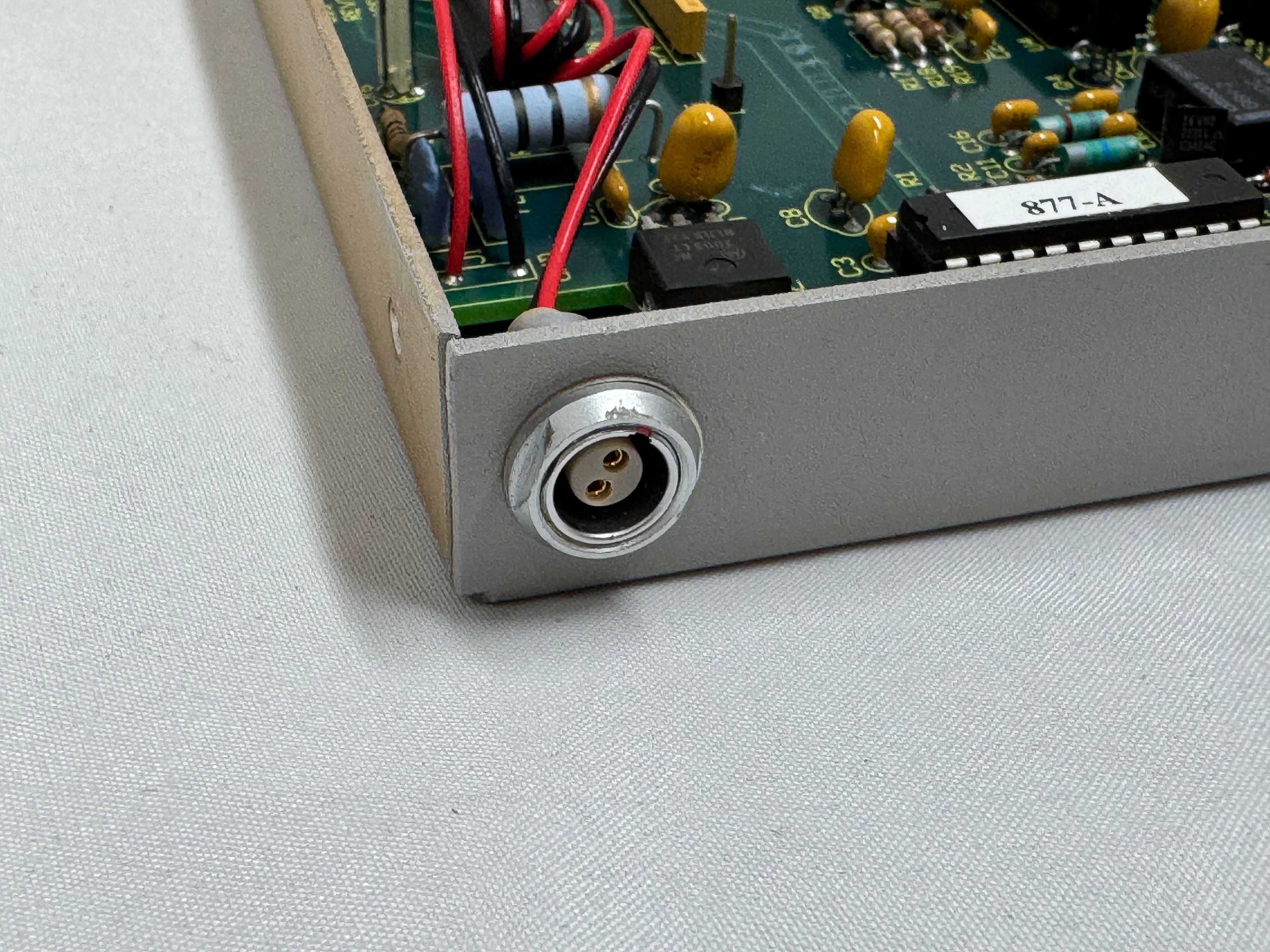
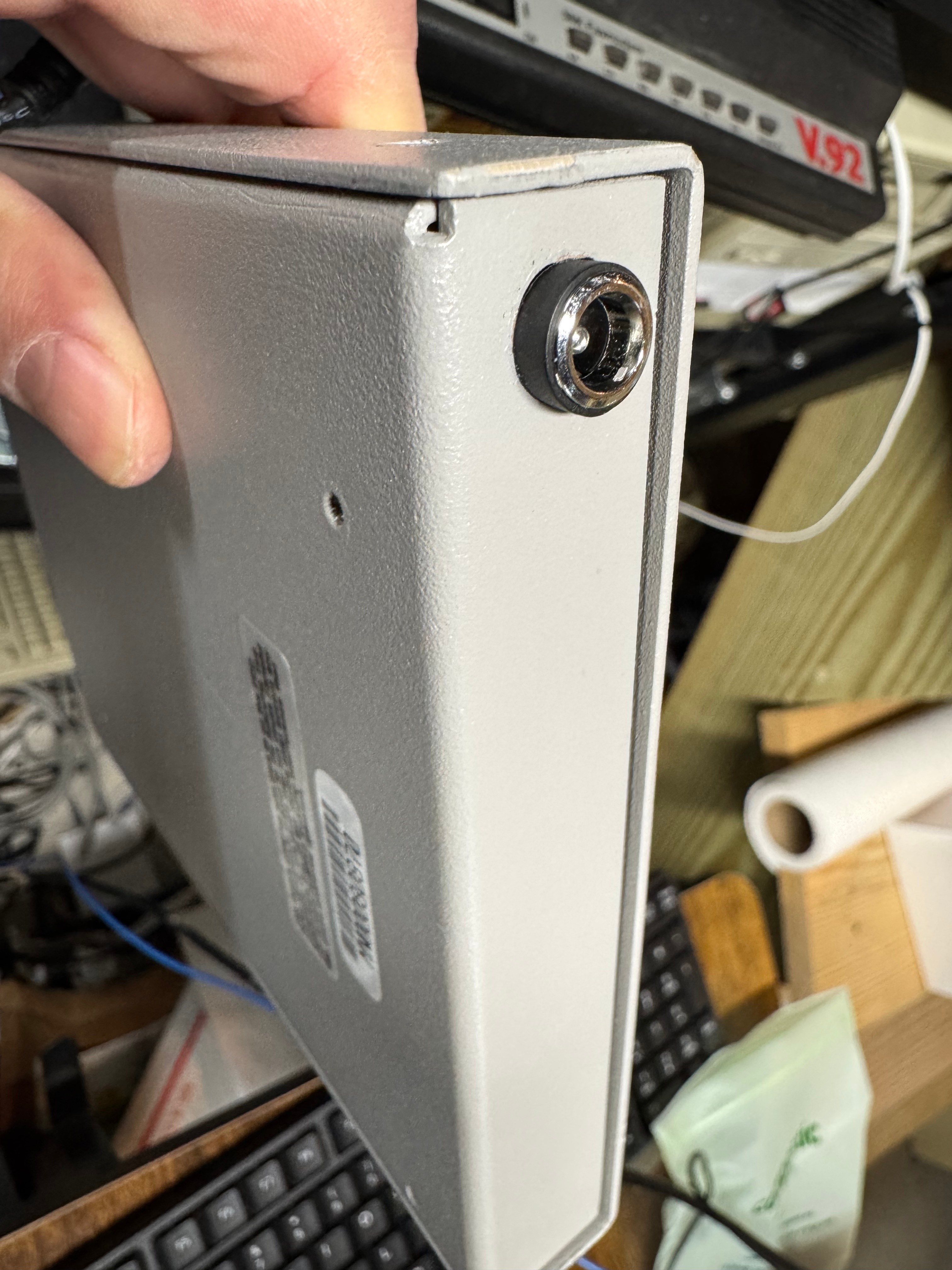
The two modifications I made to these devices were the mentioned jumper change; and they come with a FGG 2P power connector onto a RJ45 plug. It says it needs 12V on it, and I wanted to just be able to use a wall plug, I first tried to get that connector, but after finding it tiny and hard to work with, I replaced the port in the device with a standard barrel plug.

Token Ring Drivers

One difficult part of finding Token Ring cards on eBay, you never know if you can find all the drivers. The card I have is a later model PCI card. It’s a Thomas Conrad TC4048. Thomas Conrad seems to have been an interesting company putting out different network cards over the 80s and 90s before ethernet took off. It is easy to find their Token Ring and Arcnet cards online. Finding their drivers on the other hand, proved to be difficult.

Driver Hunting

I found https://archive.org/details/pwork-297 this archive.org ISO, it contains a TON of drivers for devices in the 90s. It lists TC4048 as one of them. I download the image, install the driver AND… Windows 98 says it has the tc4048 files it needs except a “tc4048.dos”. I then found https://www.minuszerodegrees.net/software/Compaq/allfiles.txt this site which has every HP/Compaq driver that used to be on their site. Those are much easier to search. There were several TC4048 items.

I found an archive at https://ftp.zx.net.nz/pub/archive/ftp.compaq.com/pub/softpaq/sp19501-20000/, and downloaded sp19859.exe, which expanded and had “DOSNDIS” and “OS2NDIS”. I knew Compaq rebranded this card, so I yoloed and renamed “DOSNDIS/CPQTRND.DOS” to “tc4048.dos” and put it with the drivers I got from the archive.org image. The Thomas Conrad drivers from different vendors had similar files with different names, but they were the exact same size, and appeared to be the same… I hoped it would just work if I renamed a file from a different vendor to the one I needed. I made progress with error messages now seeing “svrapi.dll” missing in C:\Windows\, and found that file in C:\Windows\System32… and just copied it up one directory…

And magically that worked! I had a 16mb/s connection working between the Cisco 3825 (core) and the Windows 98 PC (edge)! The core of my retro network is a Cisco router. I purchased this Cisco 3825 system a while back because it’s the last one that supports Token Ring, but new enough to have 1gb/s uplink port to my core network. This allows me to host some retro VLANs internally, and firewall them off for security (since none of these systems have gotten patches for decades). I can play with Novell Netware and host a file share of games for the retro systems on this network as well. Using even legacy networks to move files is still a lot easier than a ton of floppy disks. I leave this router off most of the time because it’s a bit power hungry and loud. I have written about it before, and it also hosts my dial up connections.
I now had the Cisco 3825 with a Token Ring card and Windows 98 PC joining a Ring and communicating! I have watched a bunch of clabretro’s videos on Token Ring, and I saw the same issue with the Thomas Conrad drivers that he saw with his cards, Windows joining a Token Ring network and the drivers have an odd interaction. When the computer boots, at that point it tries to join the ring, the system will stay at the Windows startup screen an extra-long amount of time as it tries to enter the ring. The system will also wait at shutdown as it attempts to leave the ring. If the Token Ring card is not plugged in, you get a message about failing to connect after a prolonged startup.

Future Token Ring Plans

I plan to play with Token Ring a bit more both as a standard networking technology alongside the Ethernet network I have. Now that I have two working MAUs I want to experiment with linking them over the ST fiber connectors they have and getting a Token Ring connection over fiber. I am pondering learning FPGAs by building a Token Ring to Ethernet bridge using an FPGA connected to an ISA Token Ring card. I just find it interesting and it would push my FPGA skills; the project would need to translate the headers of Token Ring at layer 2 to Ethernet headers.

Token Ring is the layer 1 and layer 2 technology, after that we use standard TCP/IP on top of it; this has made it easy to get started with Token Ring over another protocol like AppleTalk or IPX. Once the physical connection was up, and devices could enter the ring; I was able to use standard Cisco commands and create a routable DHCP pool for Token Ring.

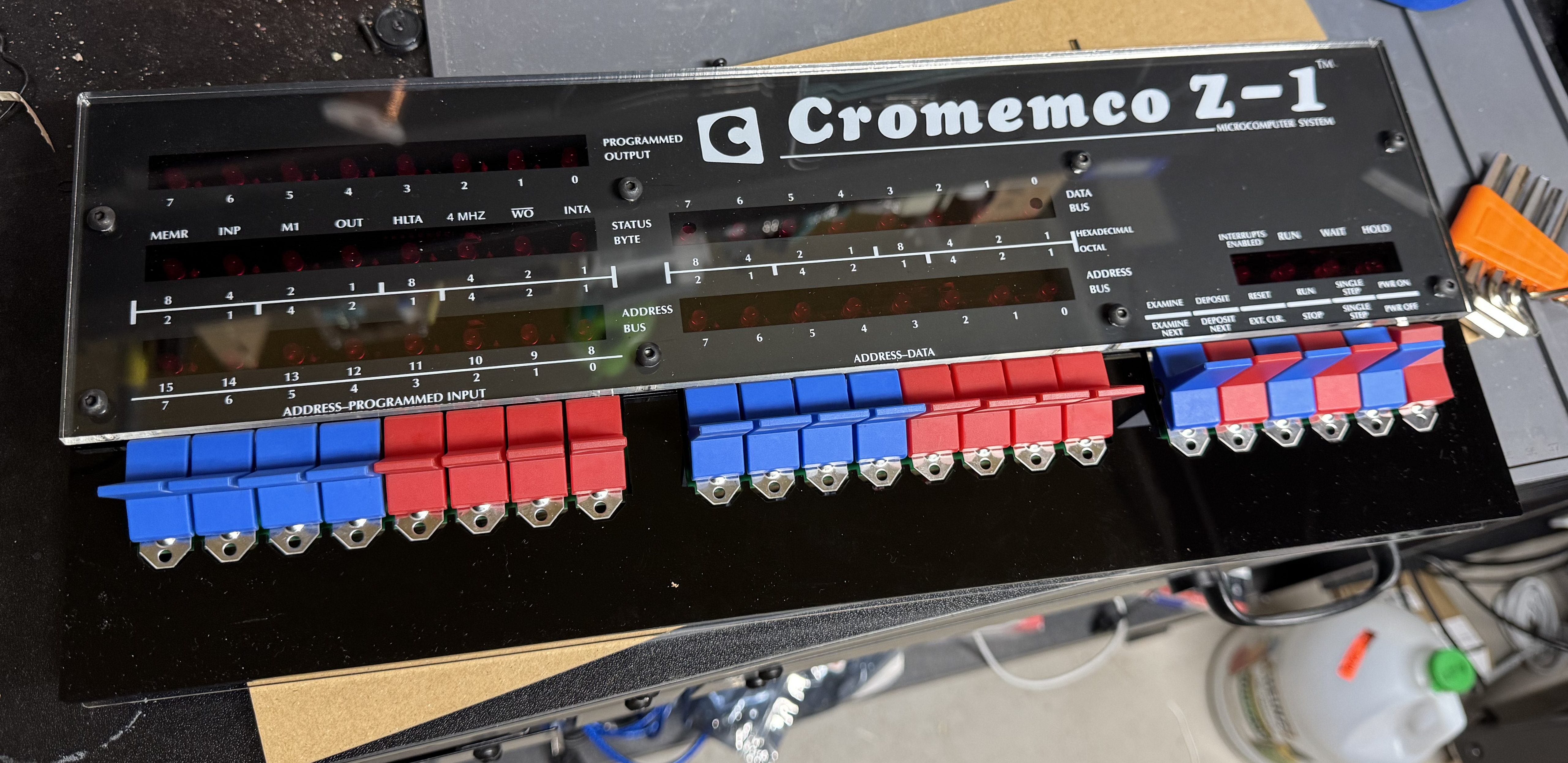
The High Nibble Cromemco Z-1 Replica

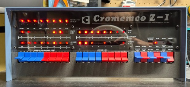
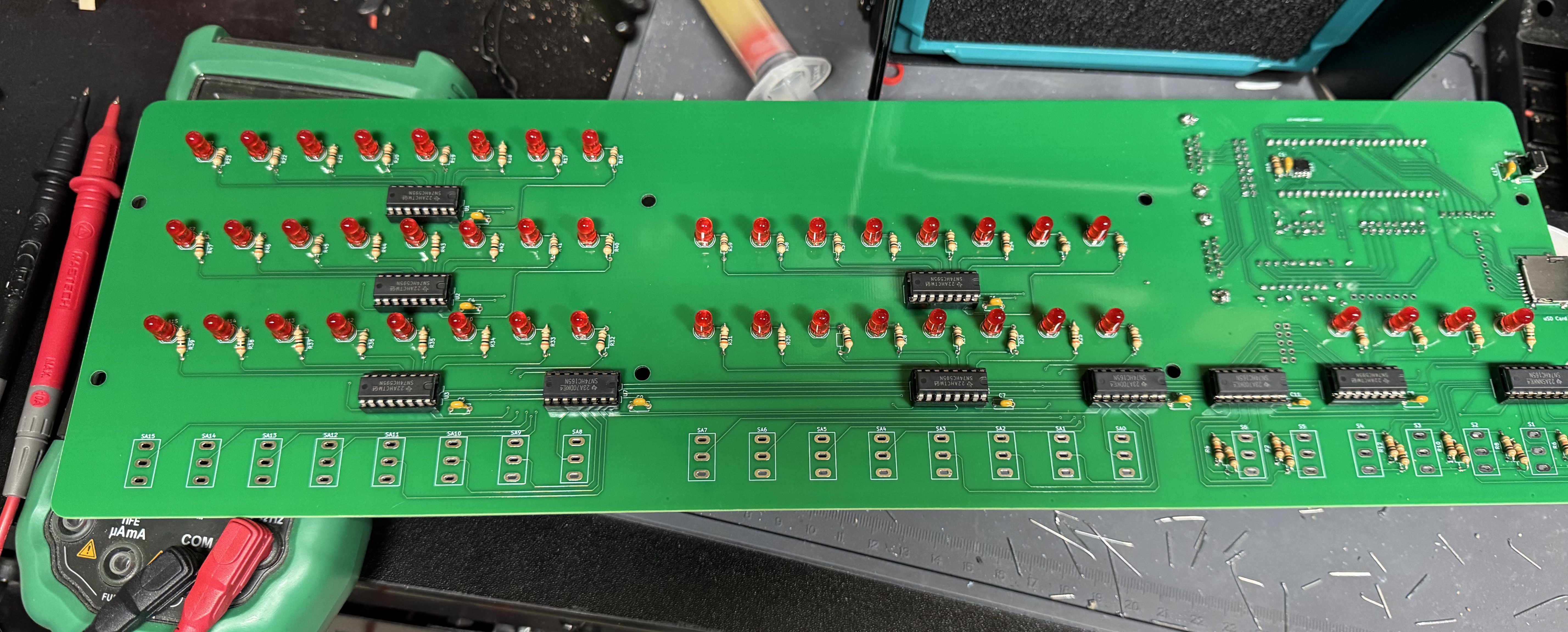
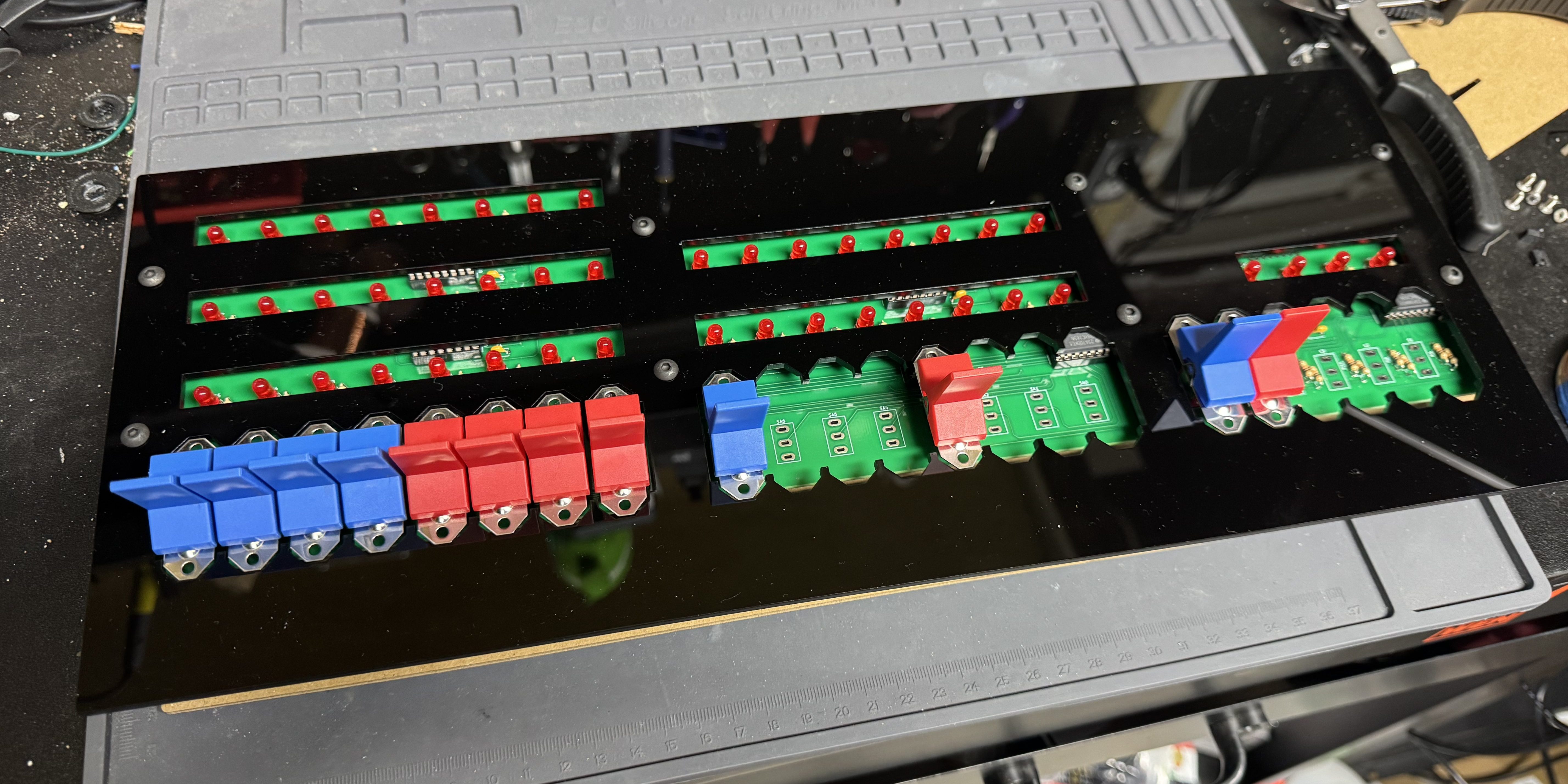
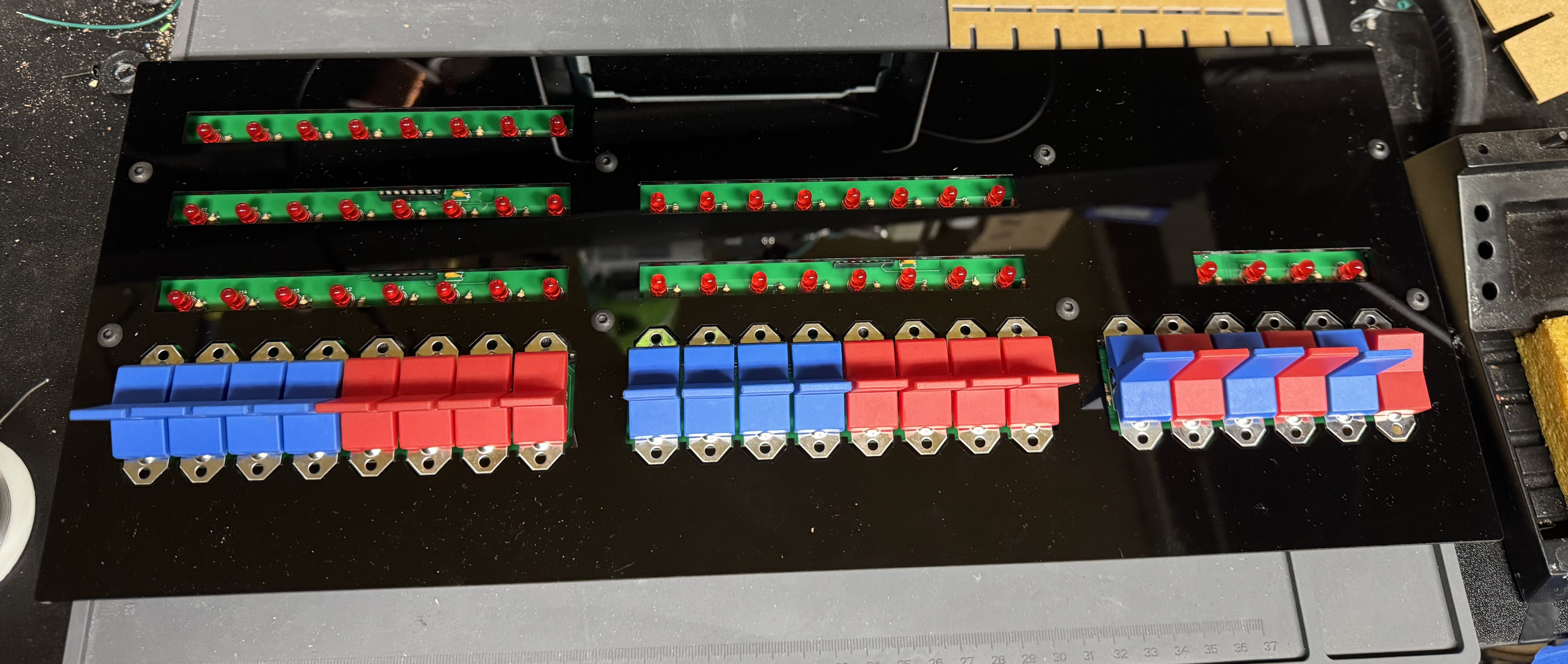
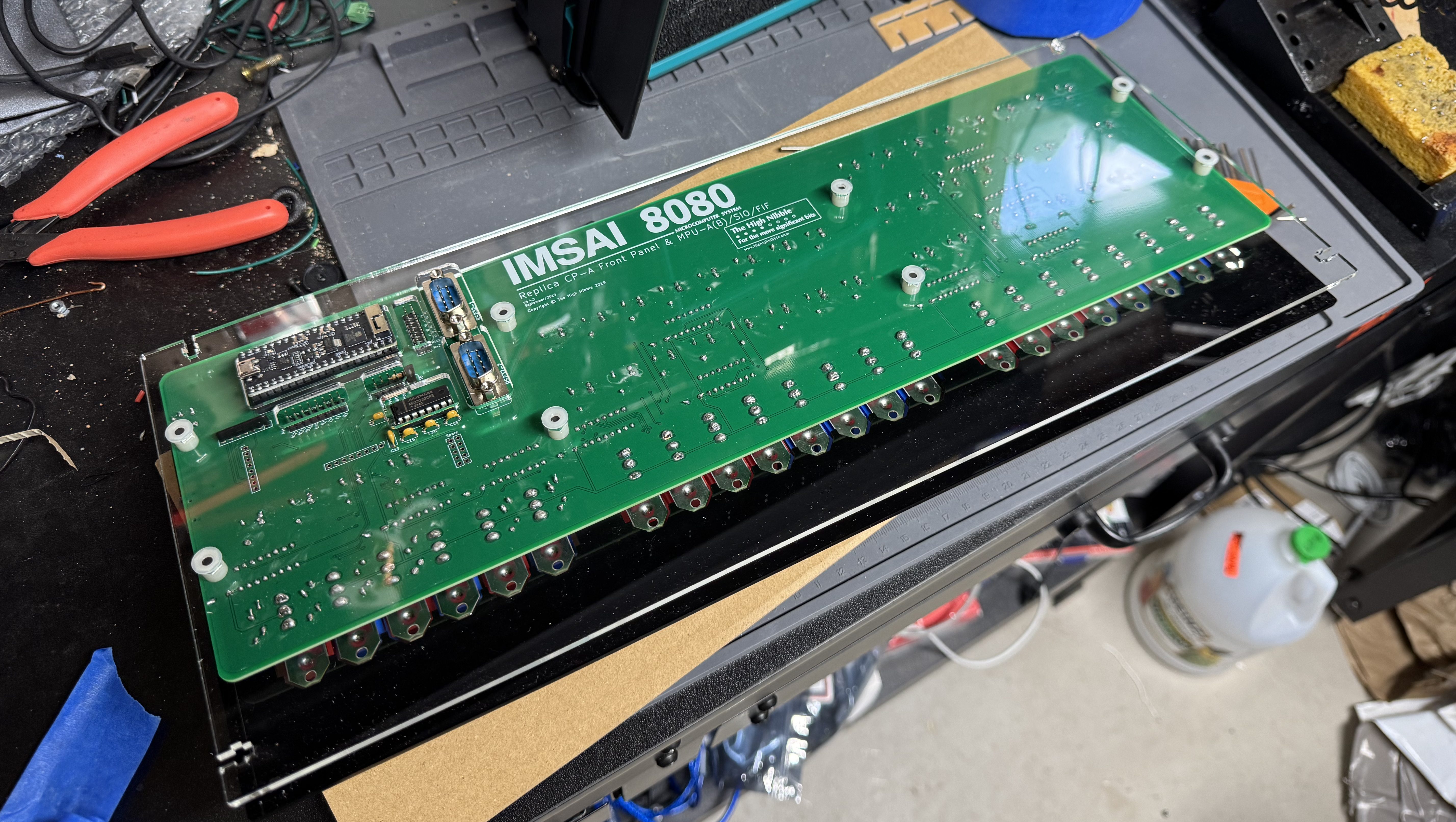
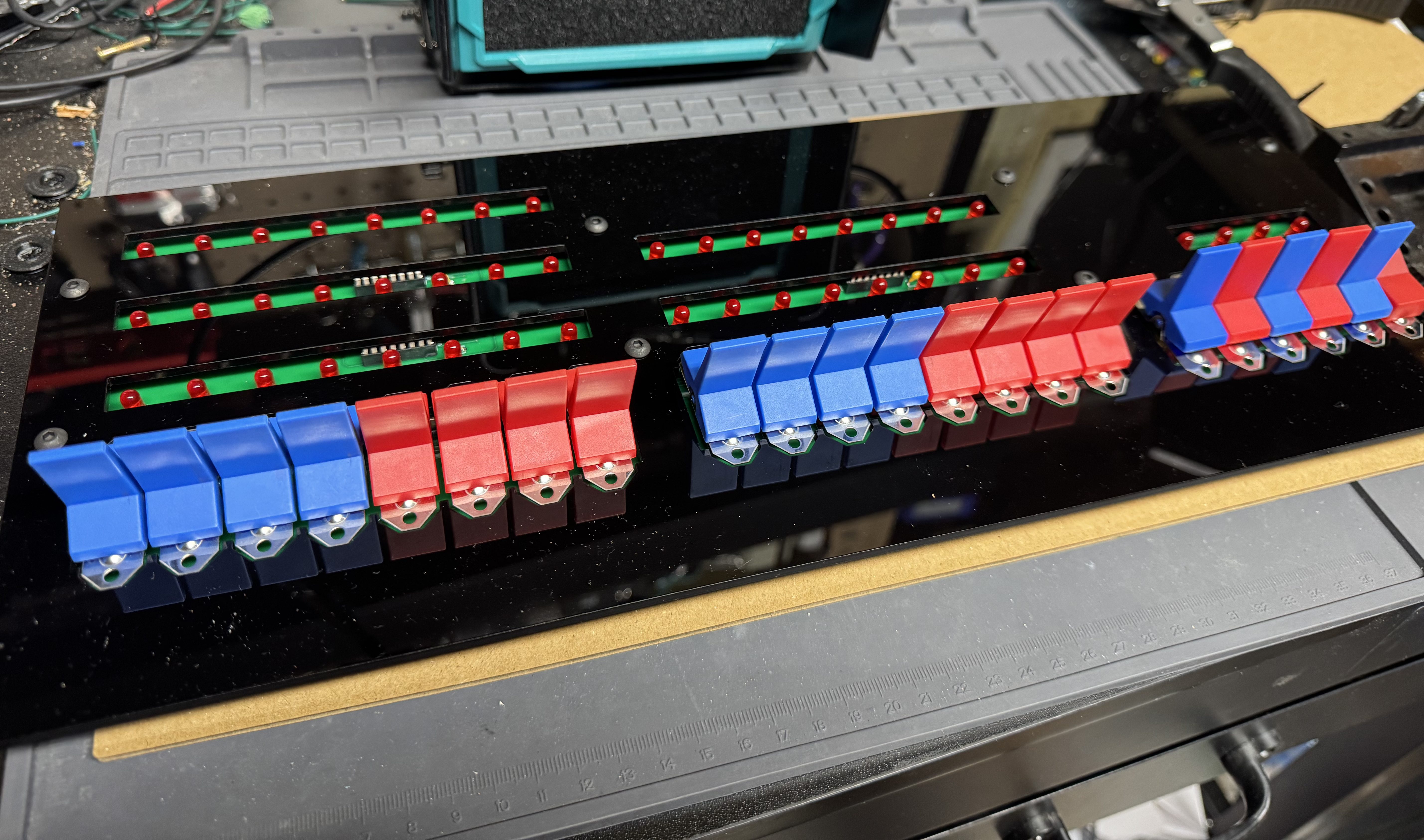
The High Nibble is back with another fun retro computer kit. This one of the Cromemco Z-1. I reached out to the creator of the kit when it first went up, and he asked if I was sure I was interested. The kit is 99% the same as the IMSAI 8080, including most of the components except the acrylic panel and new firmware. The kits are so similar the PCB for the main board is the IMSAI 8080. I enjoyed the last one so much and wanted to support the creator (not to mention a new kit means more blinky lights on the shelf); thus, I ordered the new kit.

The kits are not cheap at $300, but come with everything you need, including a ready to go controller. The packaging is done well with individually slotted spots for each switch and IC in cardboard. The metal case is a nice touch. And just like before, the firmware is fantastic. You get a full web interface, external serial ports, the gorgeous front panel, and the system can update over the air update via Wi-Fi.

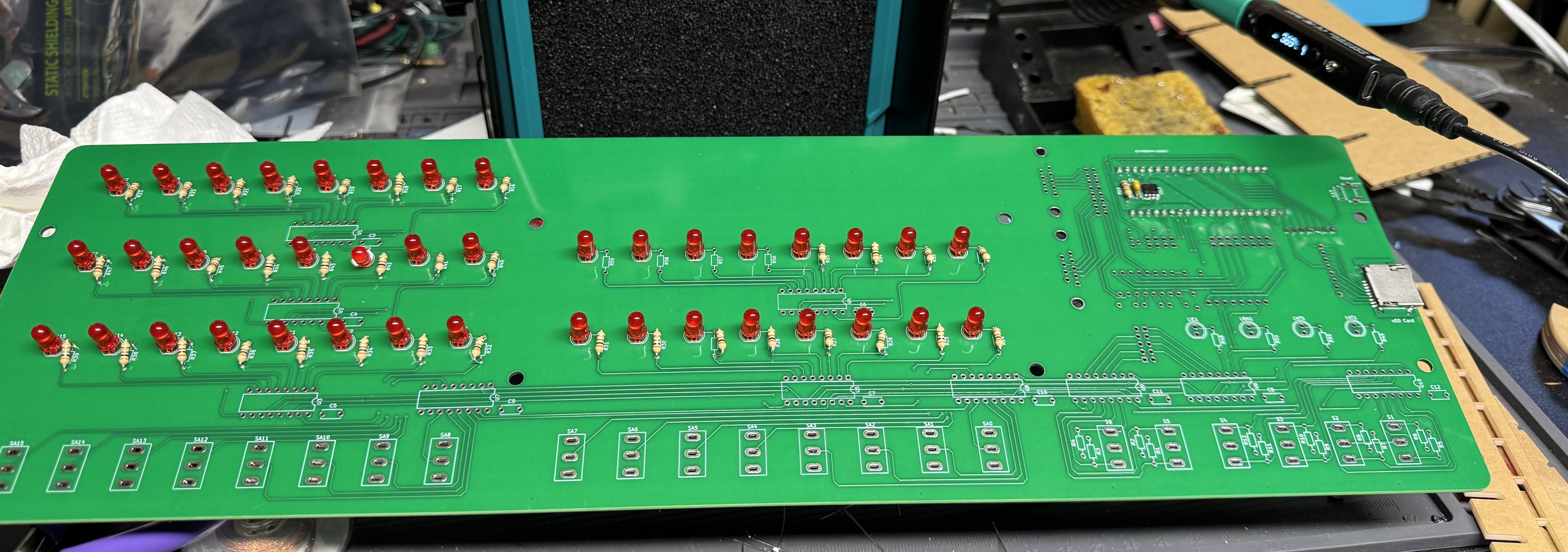
I won’t go too in-depth about the kit because it is so similar to the other one. The soldering is not too bad, the process starts with one small IC that has to be soldered in the front of the pcb, after that things like sockets and LEDs are easy, large, and straight forward.

I got a new soldering iron, the Pinecil from Pine64. This was my first project using it and I found it delightful. It’s smaller than my old iron, making it easier to handle. It’s advertised as a “smart” soldering iron which means when you put it down in a holder it quickly cools when not in use. A very nice safety feature.

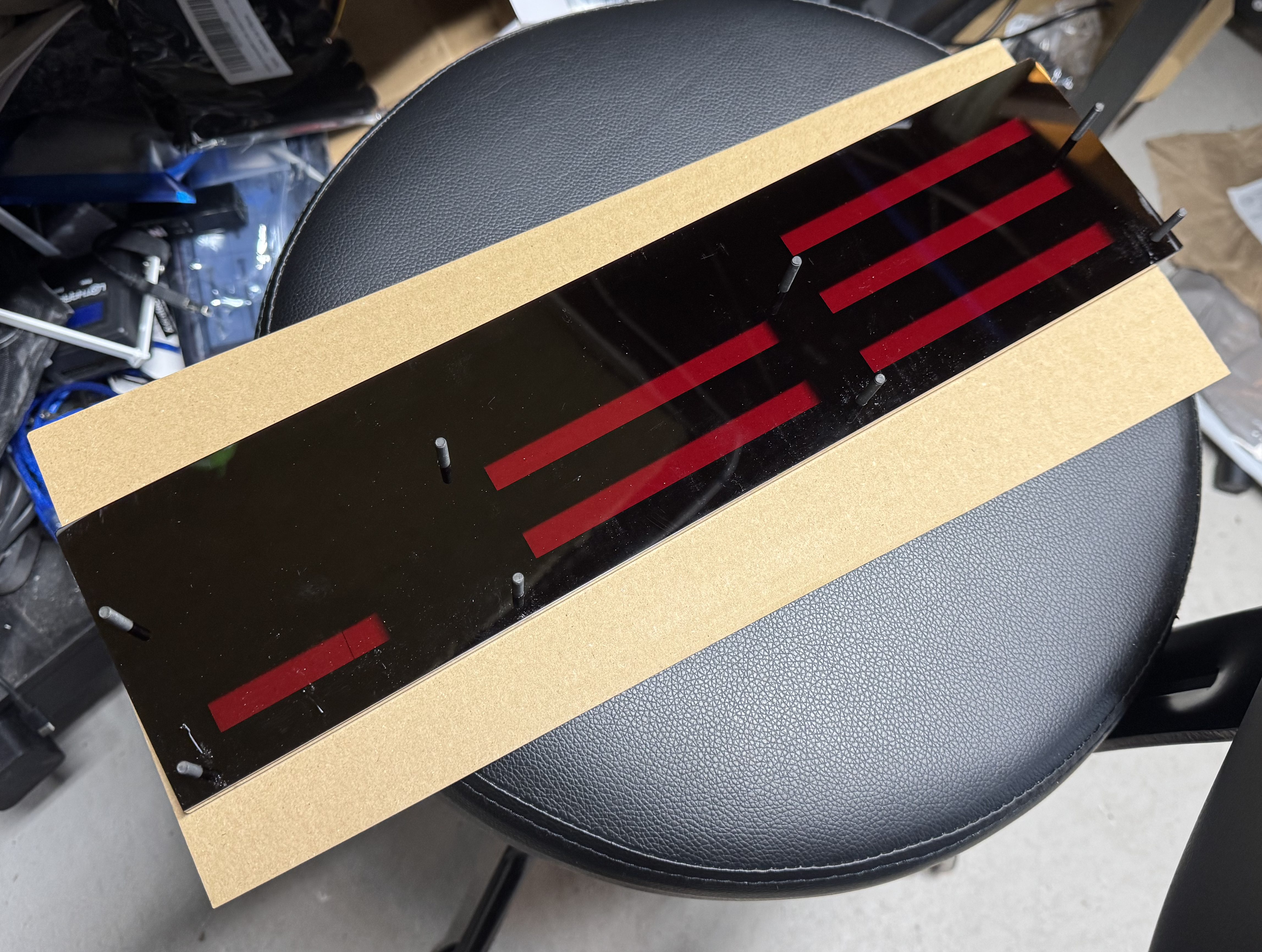
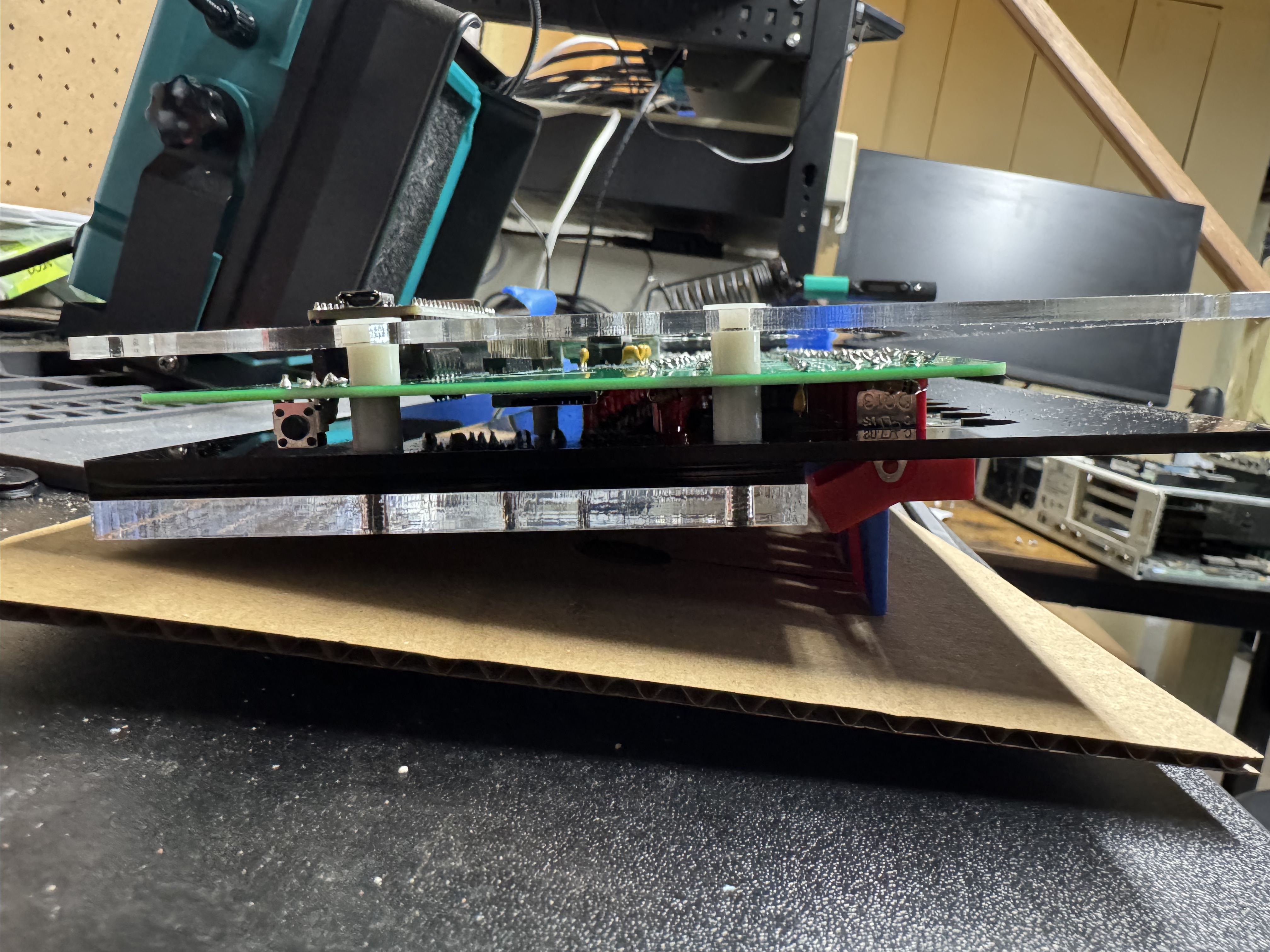
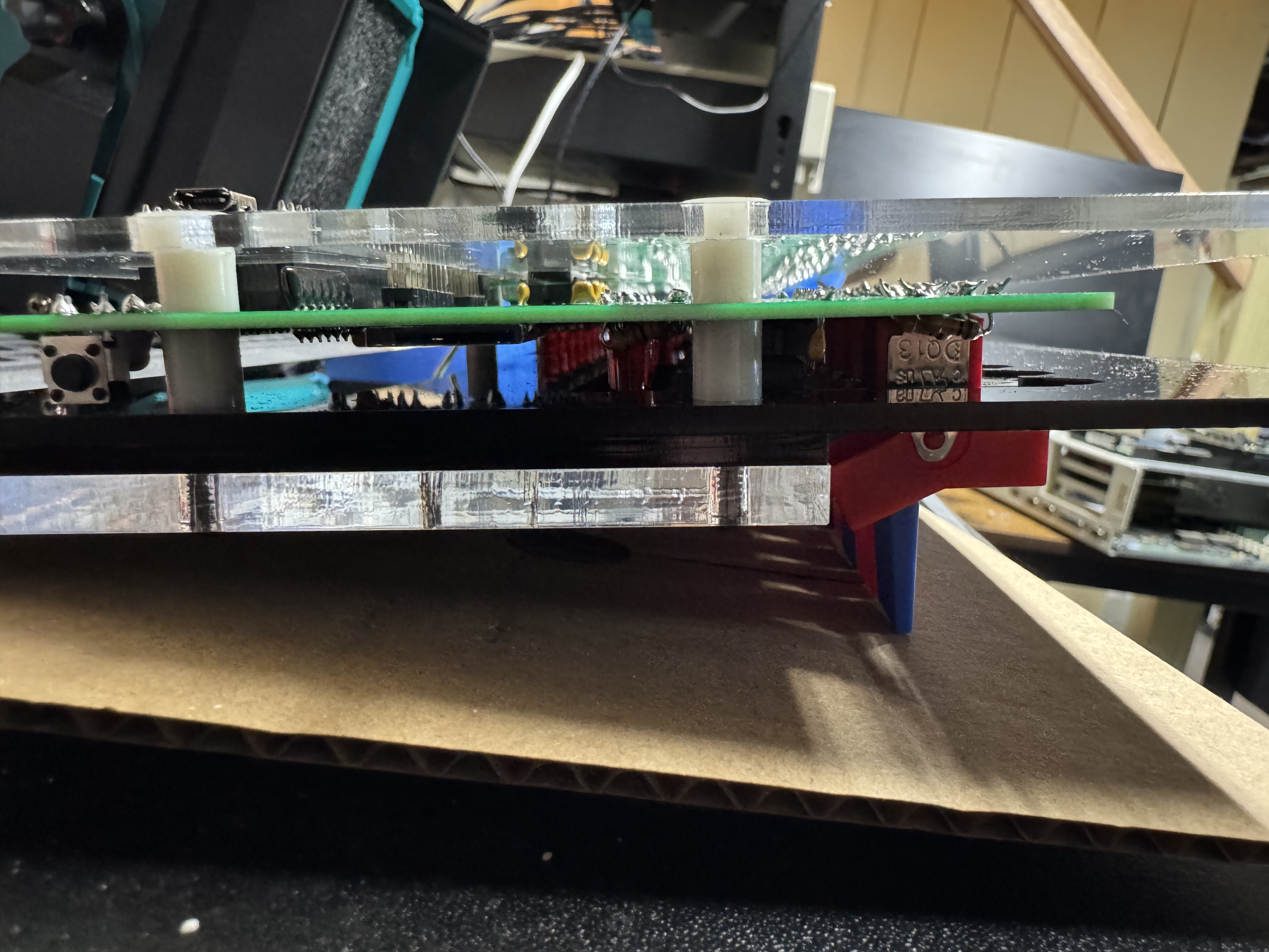
The parts of the last build that were difficult are here too, having to put the system together as a sandwich of acrylic and circuit boards it’s a bit tricky, but once you get it in the right spot tightens up easily. Tape helped keep the build aligned during assembly.

The website for the project has a lot of good information, https://thehighnibble.com/cromemcoZ1/. There’s also a helpful YouTube video, same one as the IMSAI kit, that walks through the construction step-by-step.

The main step that gave me an issue was when you get to Testing, the LS2 light would not come on. After looking in the forums, https://github.com/orgs/thehighnibble/discussions/120, turns out that is a difference in the firmware, and it is not supposed to come on. With the video being for the other kit, it is not mentioned.

Overall, another great kit, and another fun system to add to the collection!

PS/2 to RS-232 Serial Mouse Converter

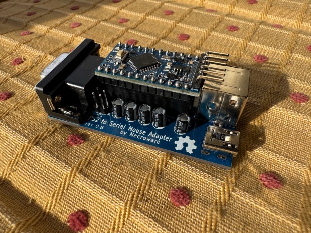
As part of my LAN Before Time rack project, I’m setting up classic PCs with a VGA and PS/2 KVM to manage them. However, one of my systems—a 486—lacks a PS/2 port for the mouse. A simple PS/2-to-serial adapter wasn’t enough; it required a proper signal conversion to work.

After some searching, I found this adapter kit on eBay: PS/2 to Serial Mouse Adapter. It’s based on an open-source project: necroware/ps2-serial-mouse-adapter. The kit didn’t include instructions, and the project assumes you already know how to assemble it; I decided to document my build process step by step.

A Quick Note on KVM Compatibility

This adapter worked flawlessly when I plugged a PS/2 HP Laser Mouse directly into the 486. However, when connected through my KVM, it worked for a few seconds before stopping. After some digging, I found a pull request from last year that mentioned a KVM fix. Flashing that updated firmware completely resolved my issue! Unfortunately, the main repository hasn’t been updated in two years, so hopefully, it gets some attention.

What’s Next?

Below, I’ll walk through assembling the adapter. After that, I’ll cover how to flash the updated firmware using a USB-to-TTL converter. These converters are cheap and easy to find—here’s the one I used: USB to TTL Adapter. Finally, I will show a case I designed and 3D printed for the device.

Steps

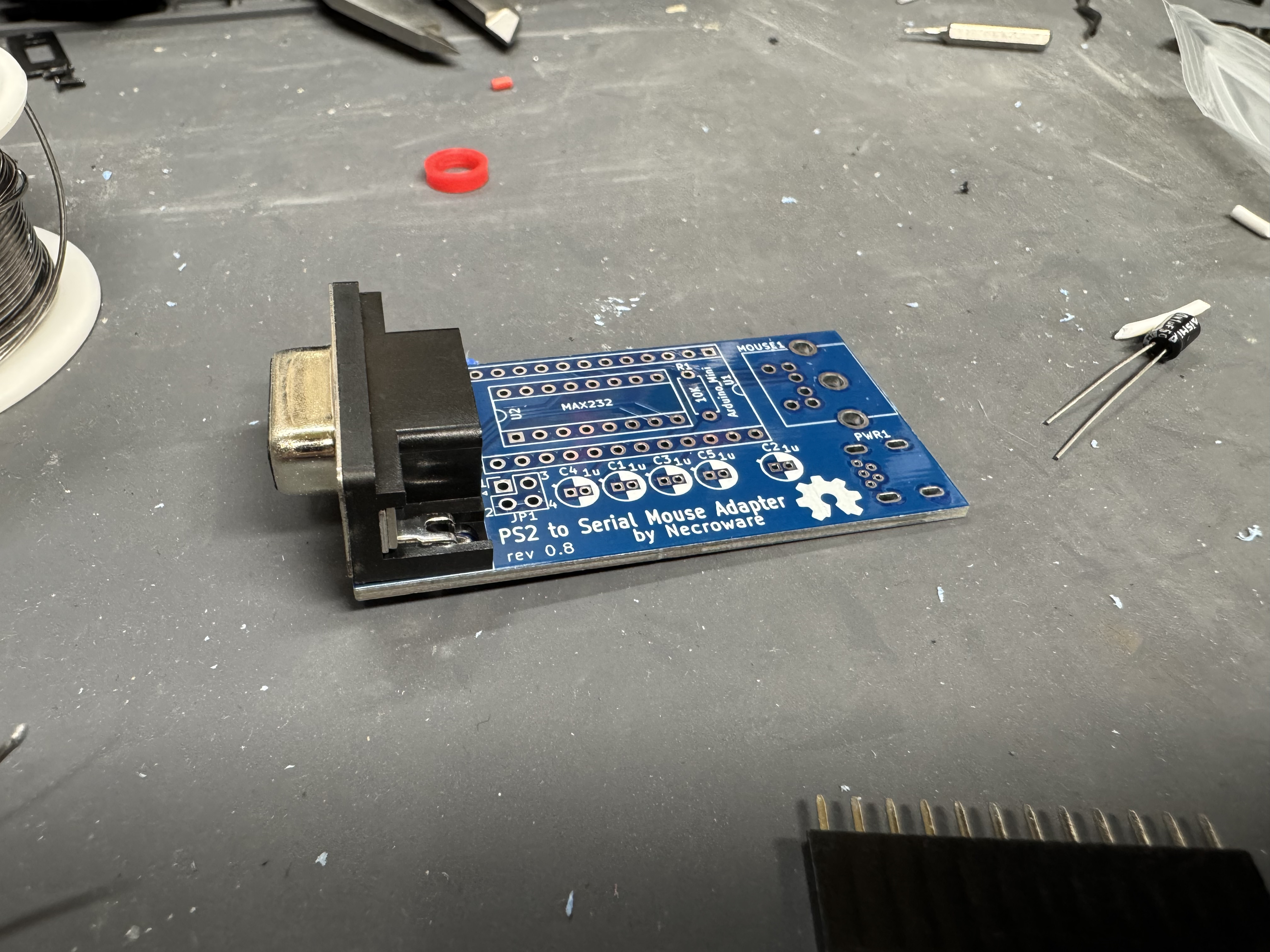
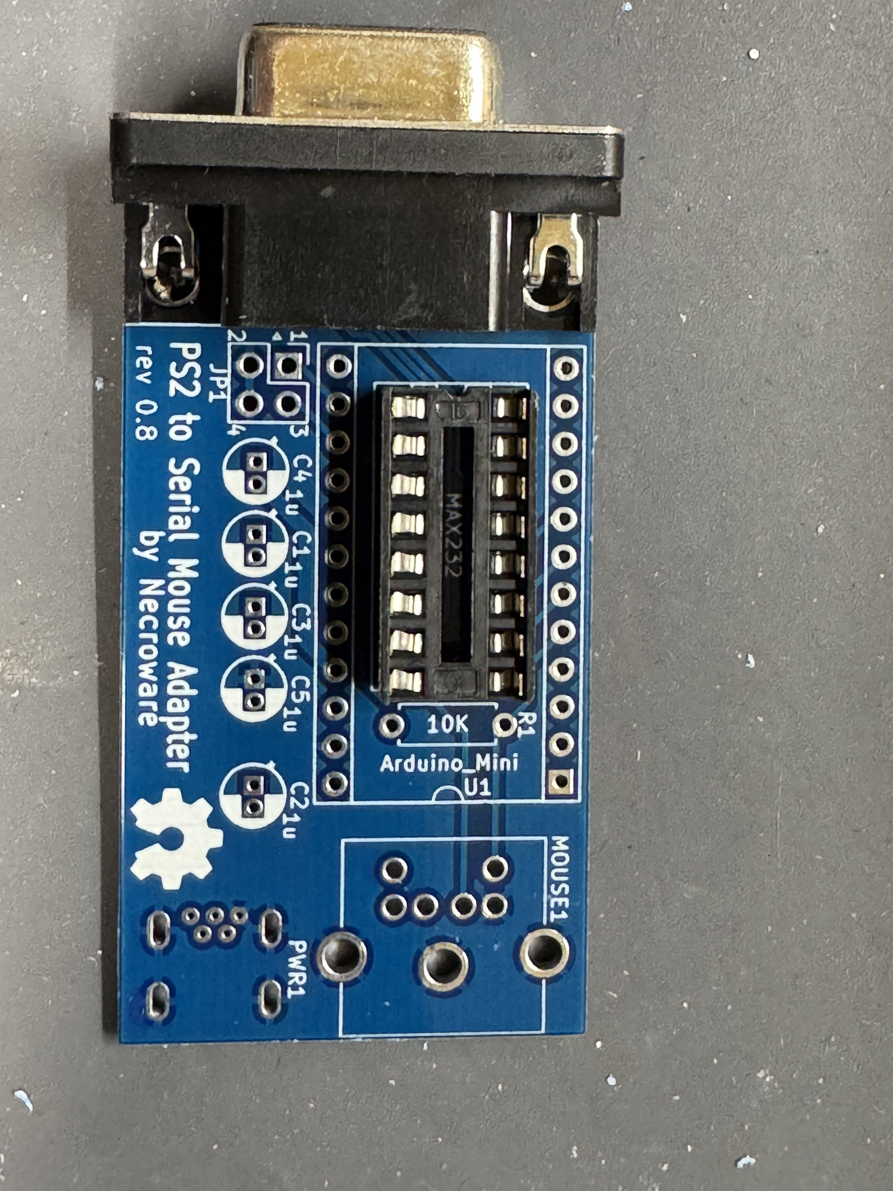
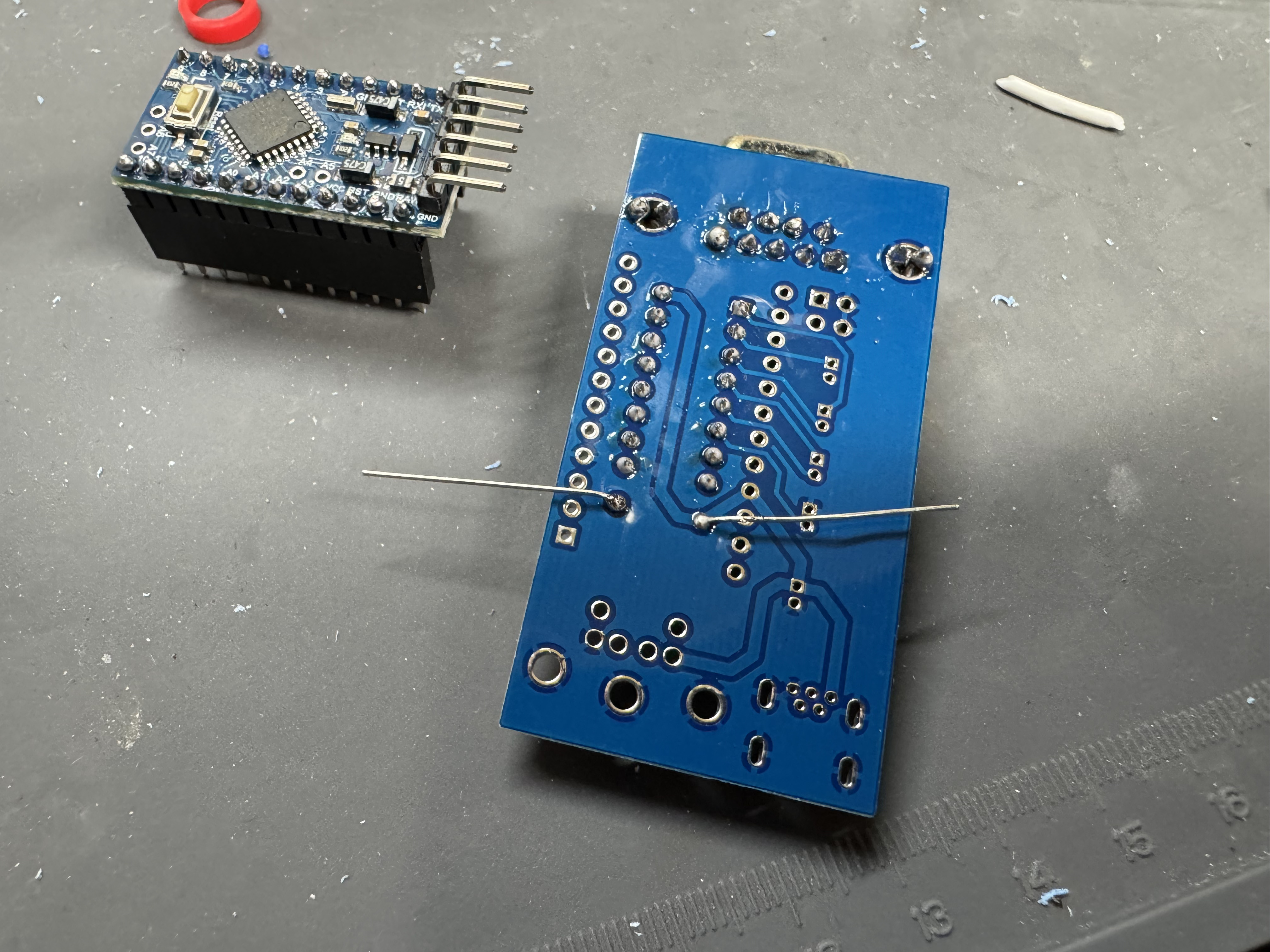
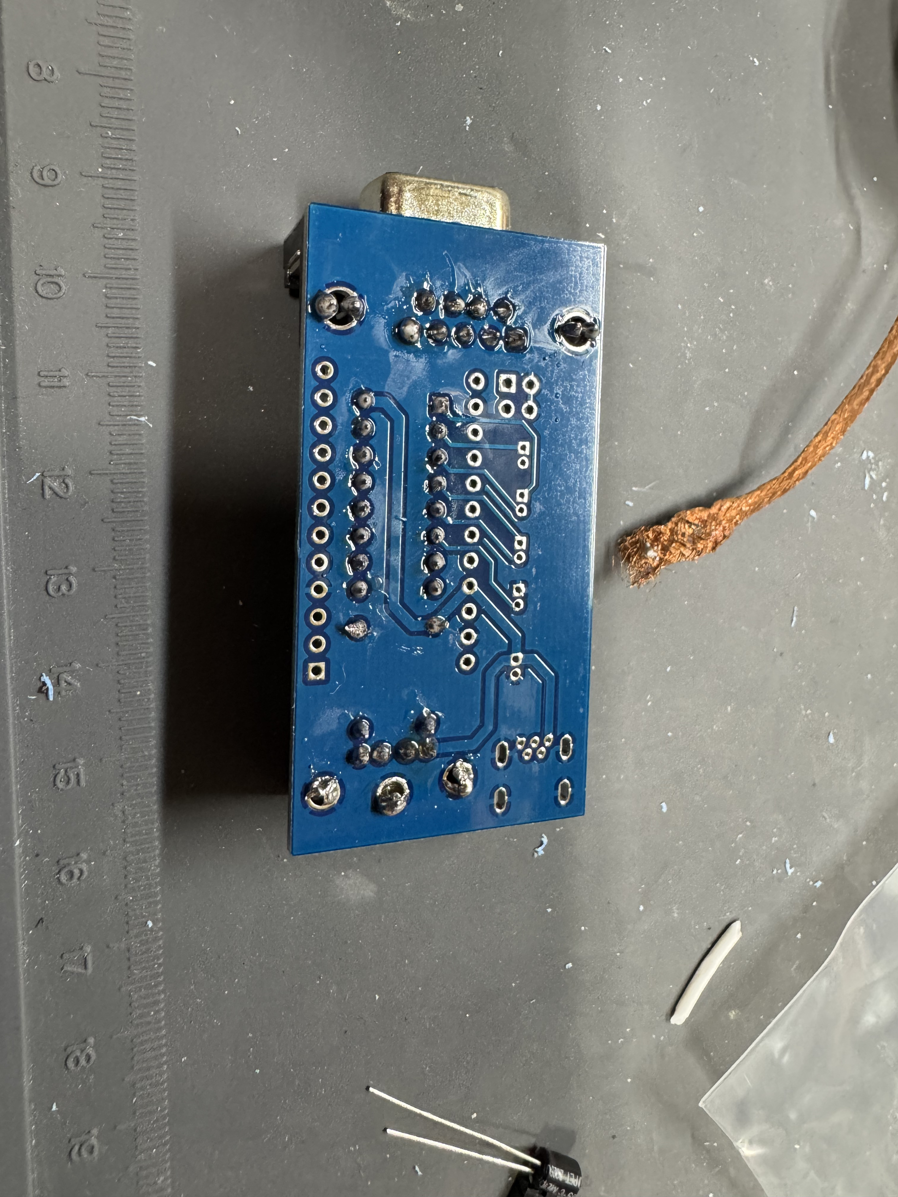
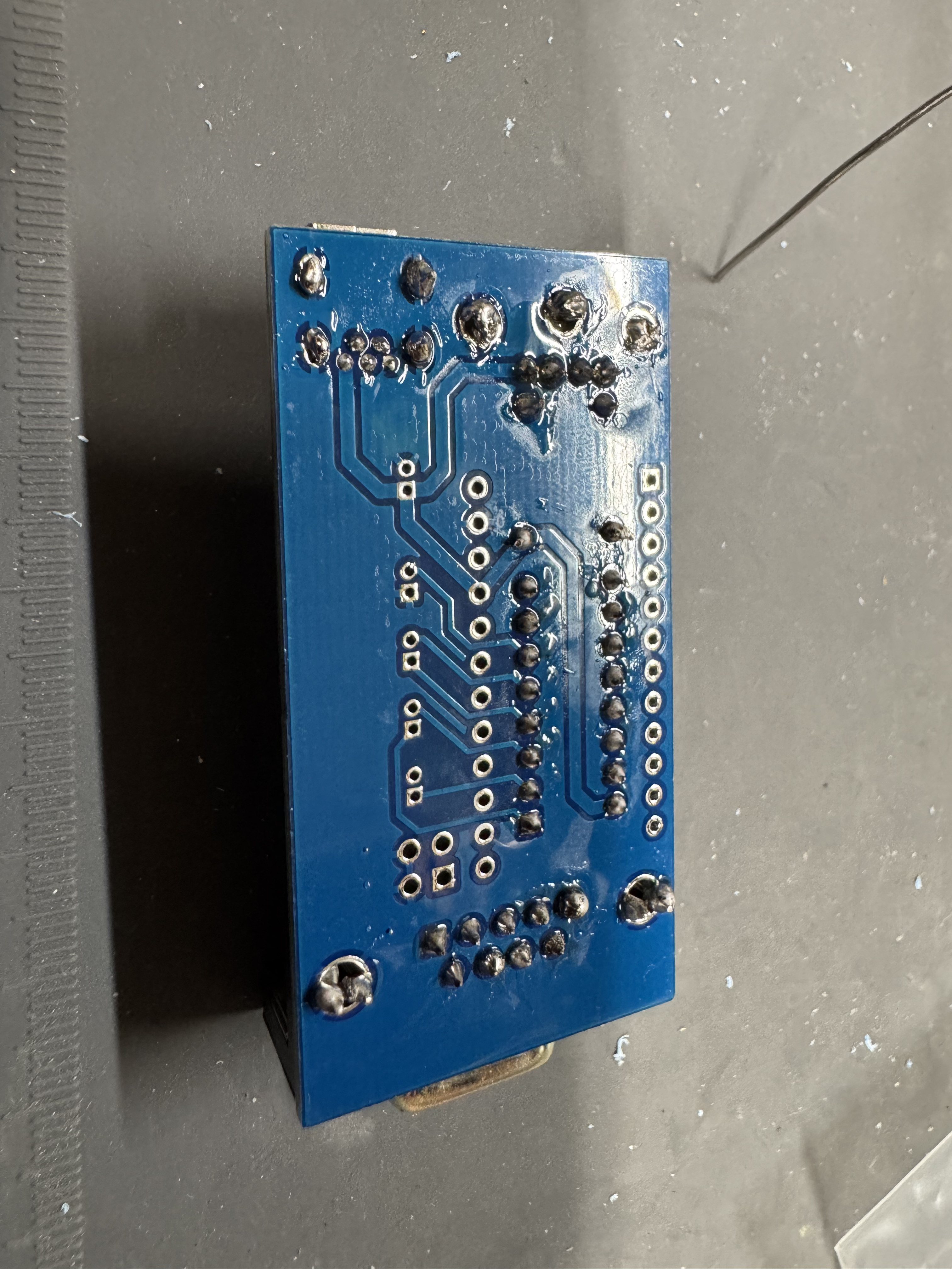
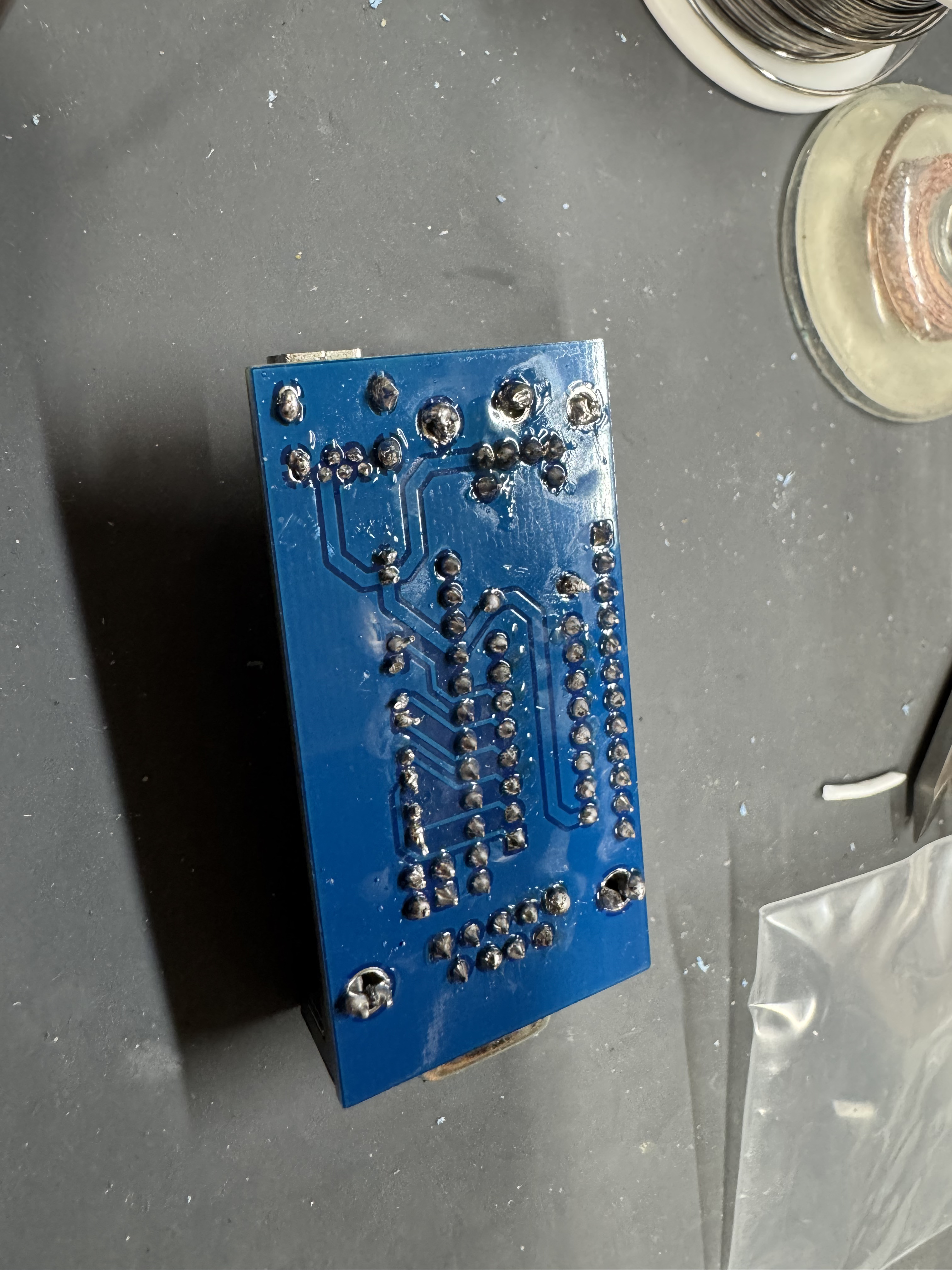
  • Put the serial connector through the top side of the board and solder it in place on the bottom, starting with the mounting legs and using plenty of solder. These take a lot of the strain of the connections. Then carefully do each of the data pins, making sure not to bridge any.
  • Insert the lower chip socket, and solder in place on the underside.
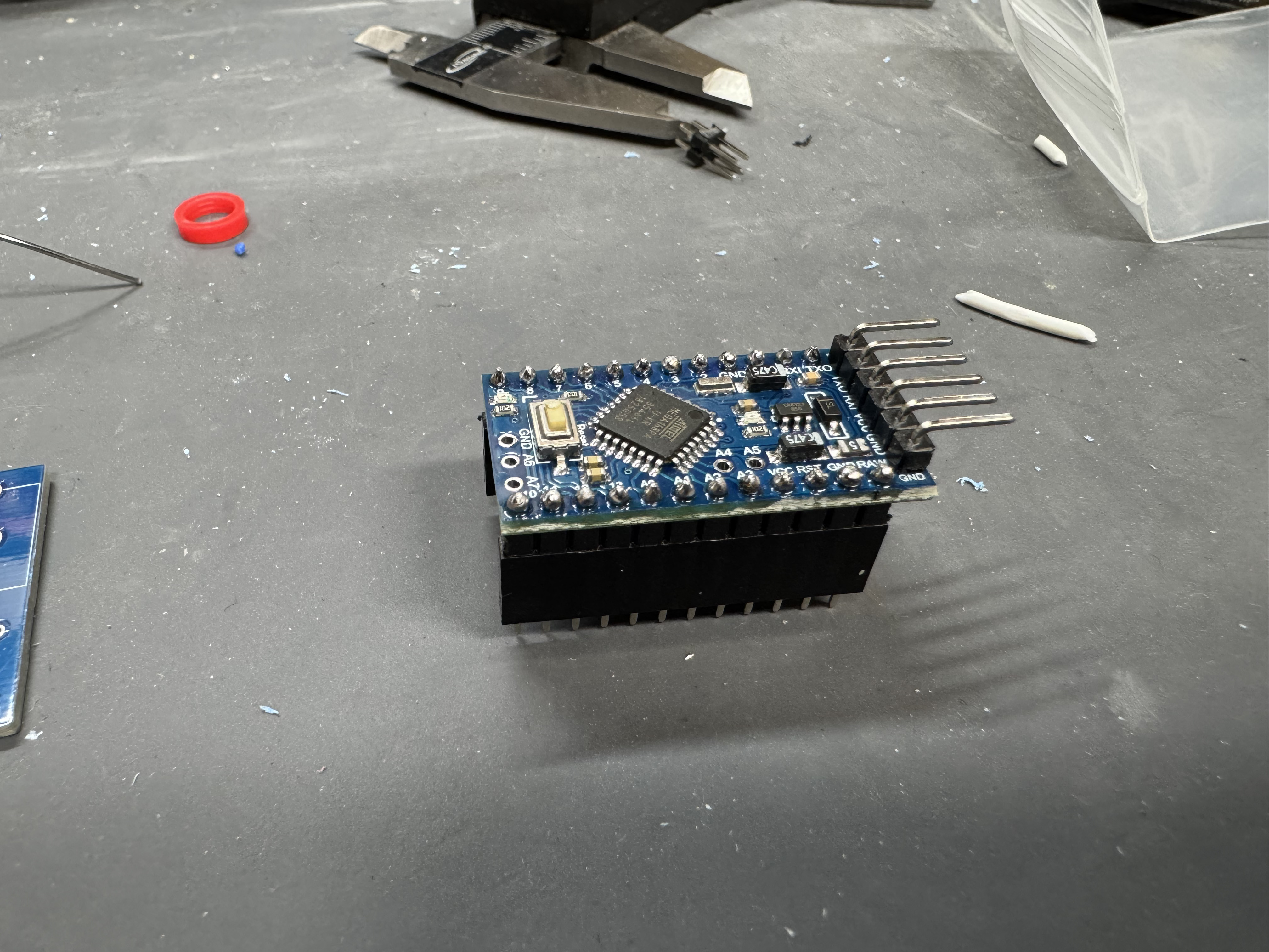
  • The Arduino Pro has 3 different parts we need to solder. The first is the head with the 90 degree pins at the end. This will allow us later to flash the controller if we want to move to other firmware. Put those through the top (the side with the chip) and then solder them in the underside.
  • Next, put the Arduino header pins in the bottom. I put them into the header connector to hold them in place. Do not put too much heat on each pin with the plastic part below. (Not my best soldering job)
  • Solder in the 10k resister, here I am soldering it on the bottom while it went in through the top. After it is in, cut of the excess legs.
  • Solder in the PS/2 port, use a good amount of solder on the mounting points so it doesn’t move when inserted, then solder the data pins.
  • Solder in the micro-usb port, careful of the tiny pins.
  • Add the jumper pins, solder them in.
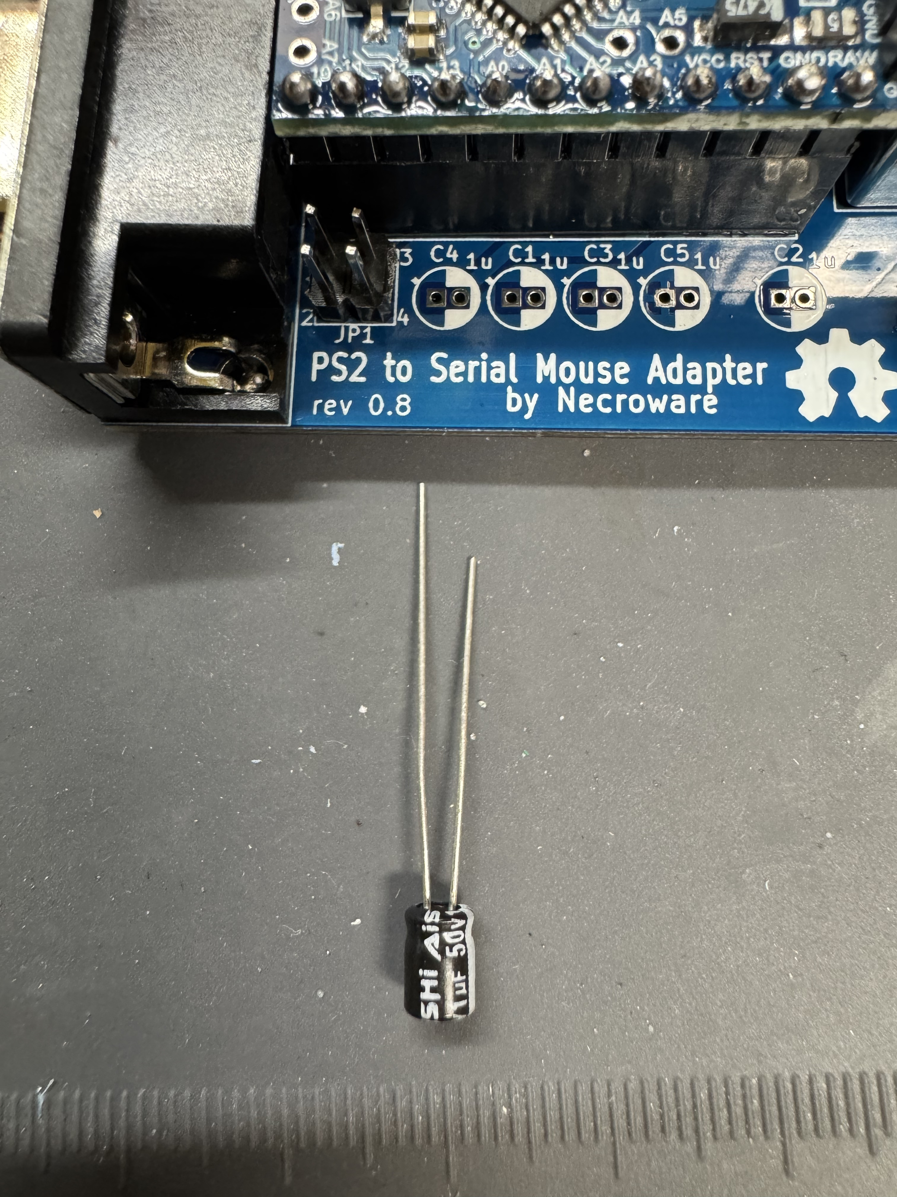
  • Now time for the capacitors, these are polarized, note the right side of the silk screen is white that should line up with the white side of the cap. (the shorter leg side)
  • Finish up by soldering all the pin headers for the controller to sit on the board.

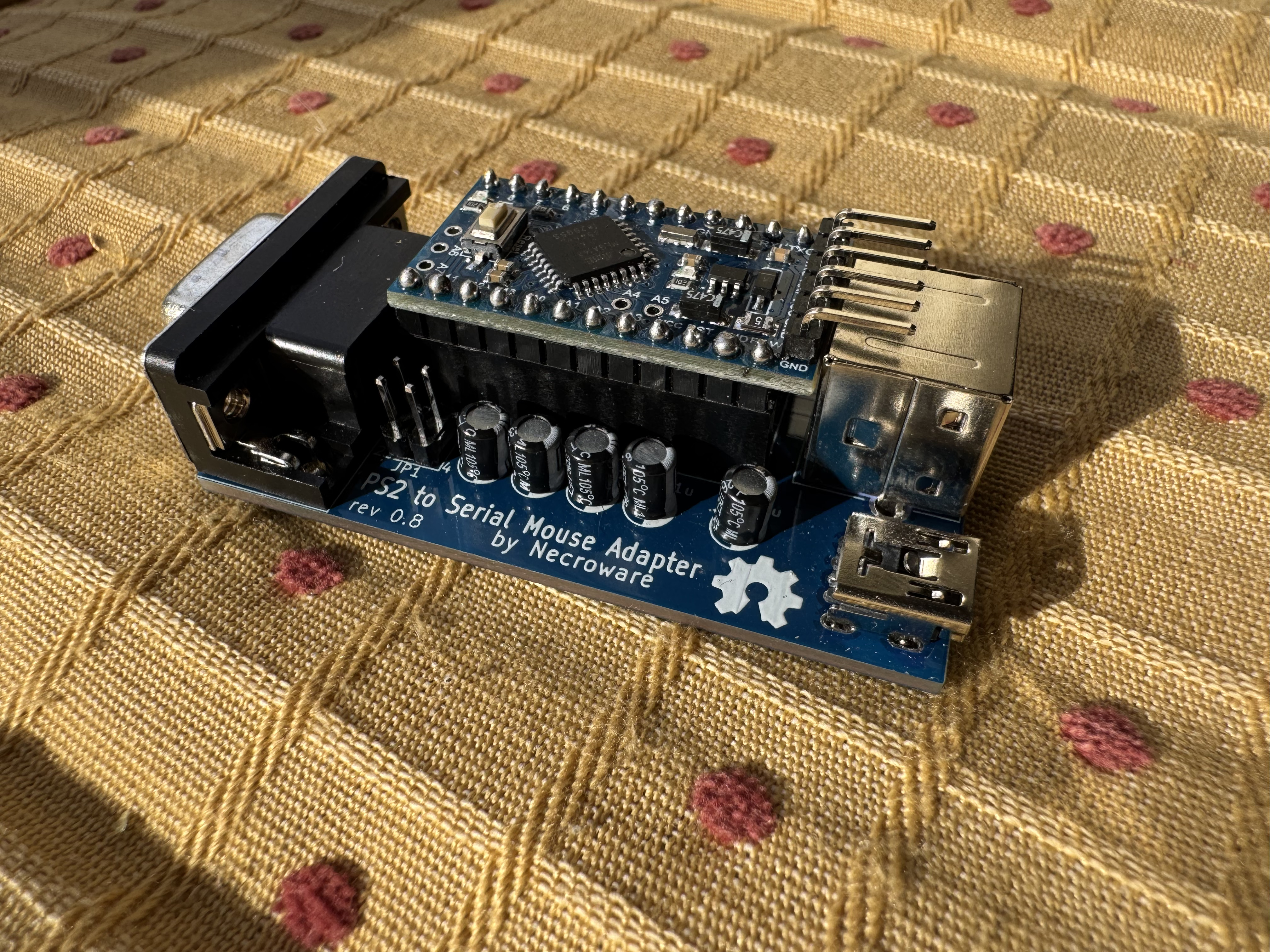
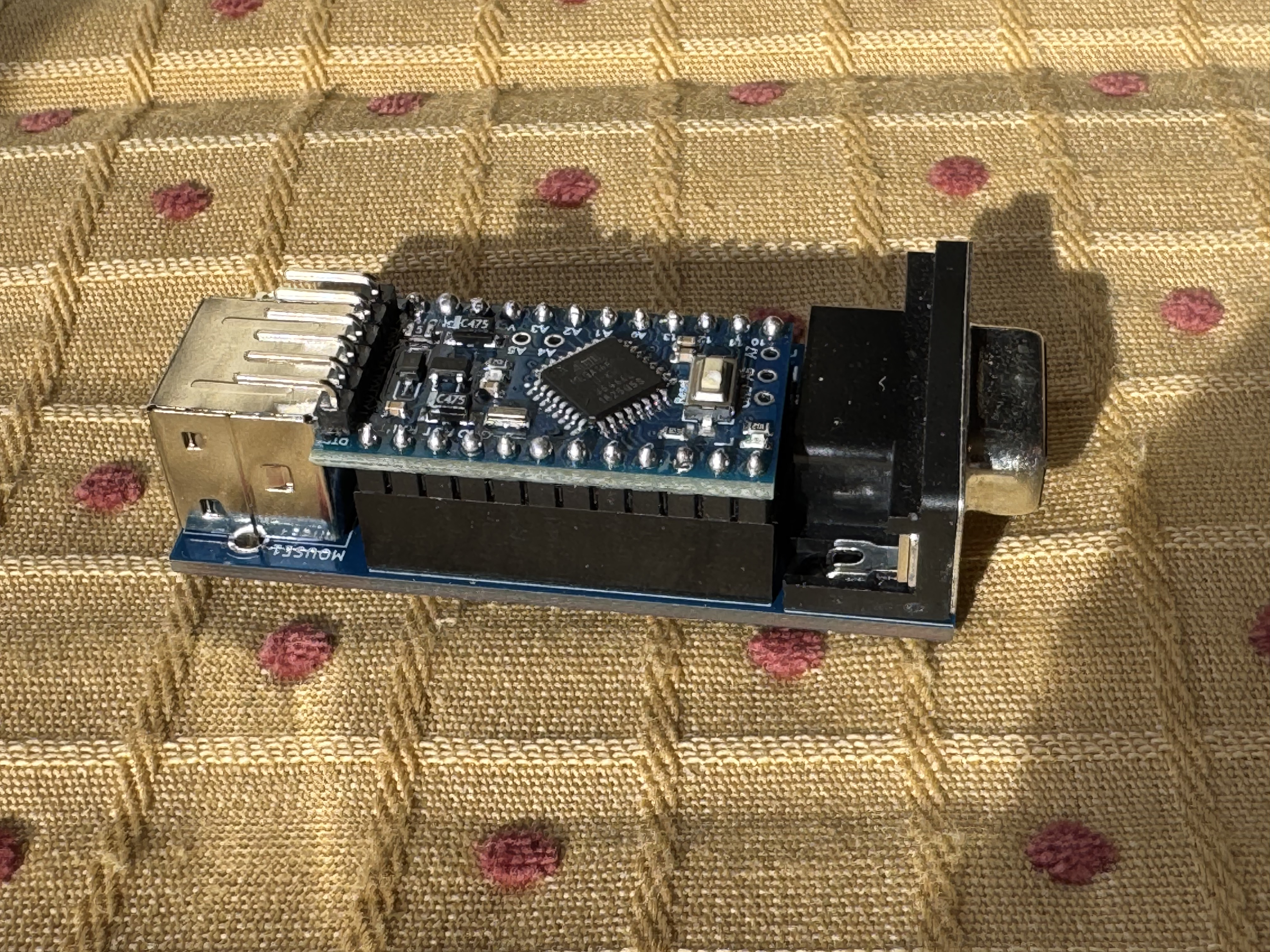
The board should now be complete! If you bought it from the seller I did, (who has been great, and I have bought other items from) then you have the main repos firmware on it. I won’t go too far in depth for this, but if you clone the fork down you can then use Platform.IO to flash the firmware. There are guides out there to do this on. Platform.IO is great when doing Arduino projects.

If you go the same kit I did, then it comes with a “pro16MHzatmega168” not the “pro16MHzatmega328” used in the Pull Request. Change the two lines where the 328 is mentioned to the 168-model string. If you do not, you will get a “timeout connecting to Arduino” when attempting to flash.

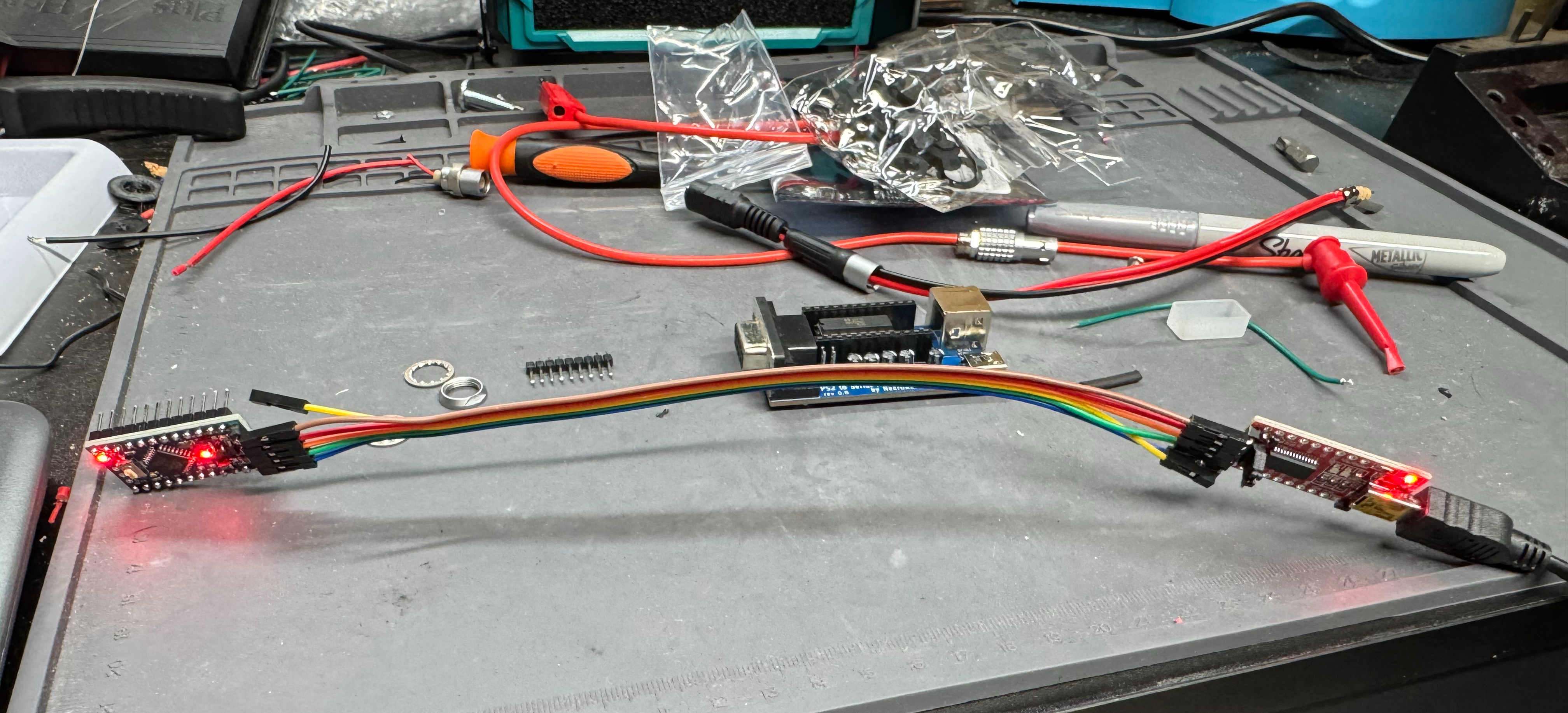
As mentioned, you need a TTL converter, then to flash the chip. The TTL converter (which I hadn’t used before) pins actually line up with the pins on the Arduino Pro. You need to hold it there for a total of 30 seconds while it flashes. You can just stick the header pins of the Arduino through the holes of the converter, then hit send via Platform.IO.

Flashing the new firmware on my messy desk, I did not need long cables like this…

3D Printed Case

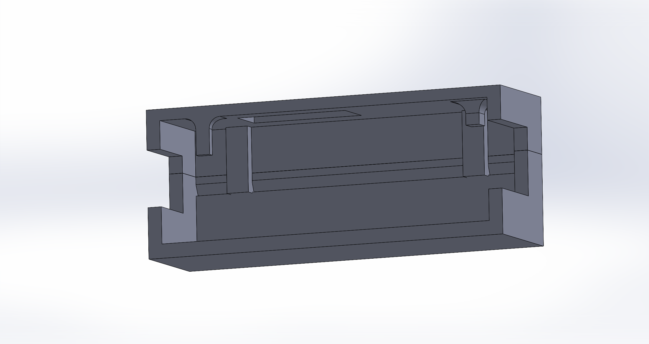
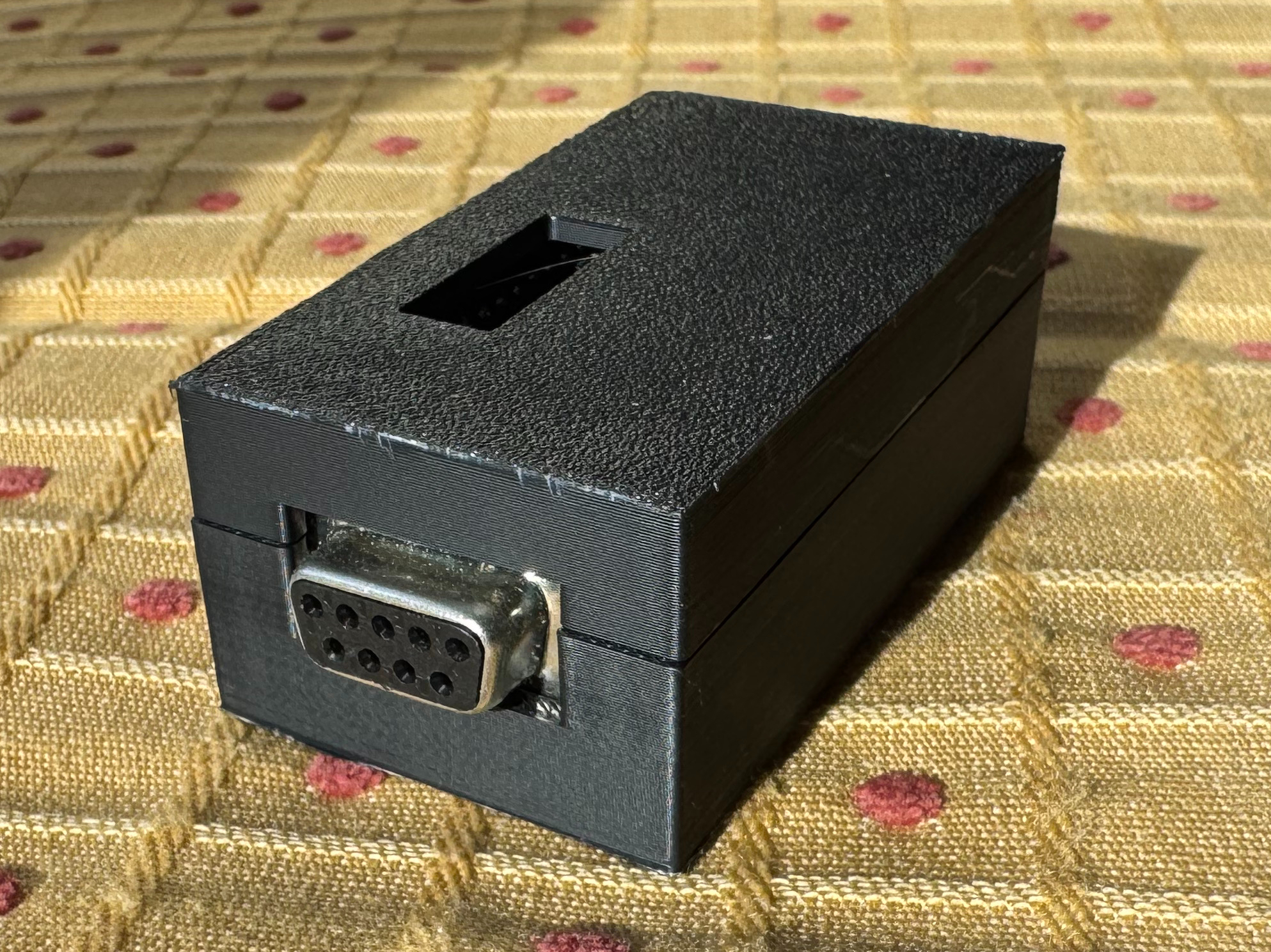
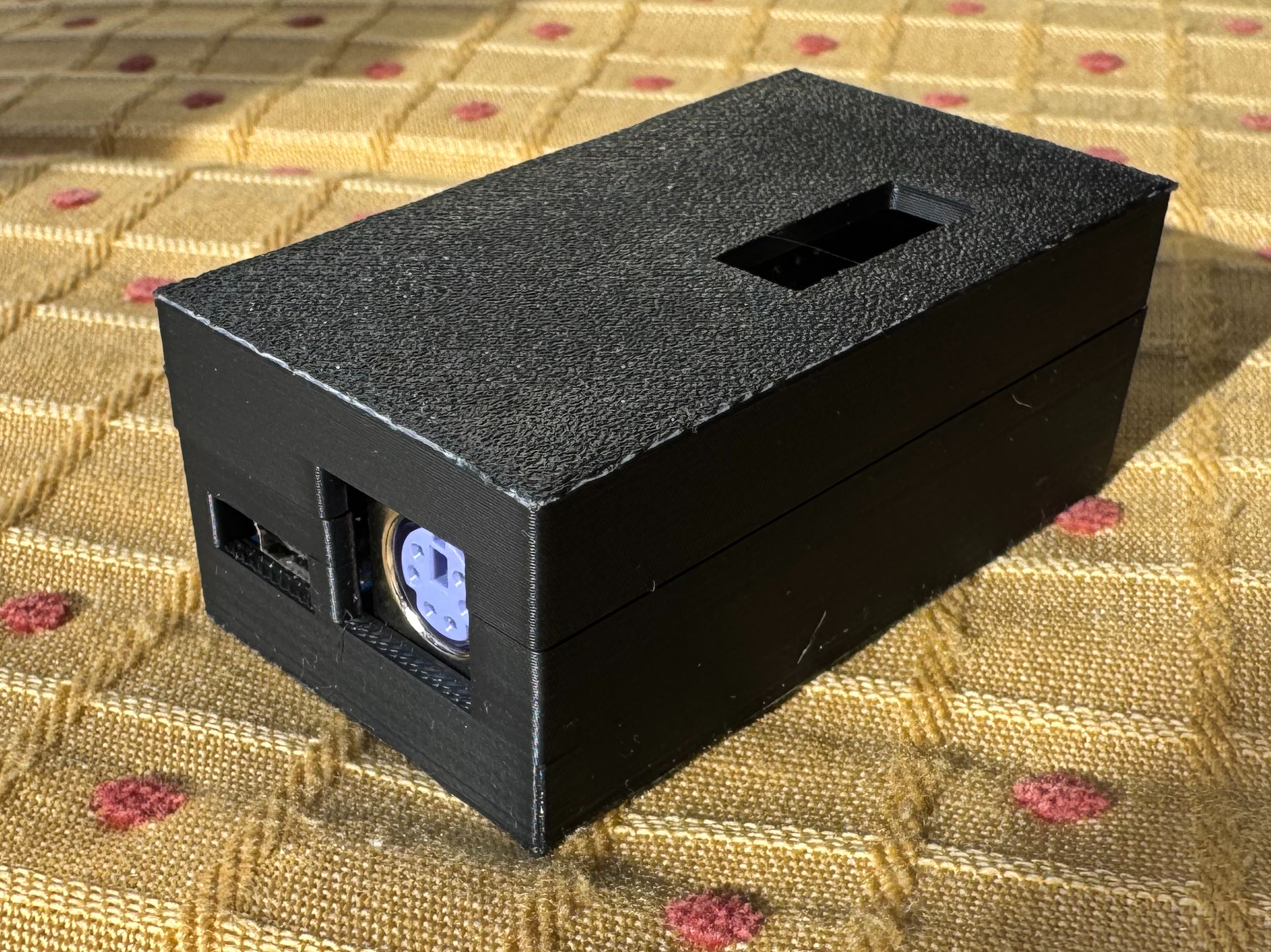
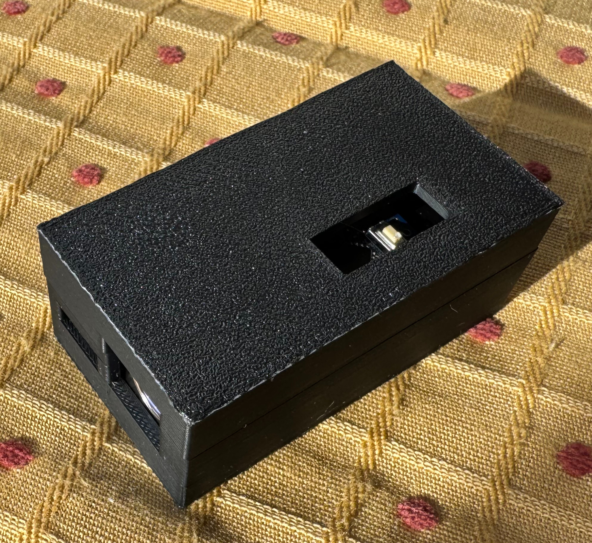
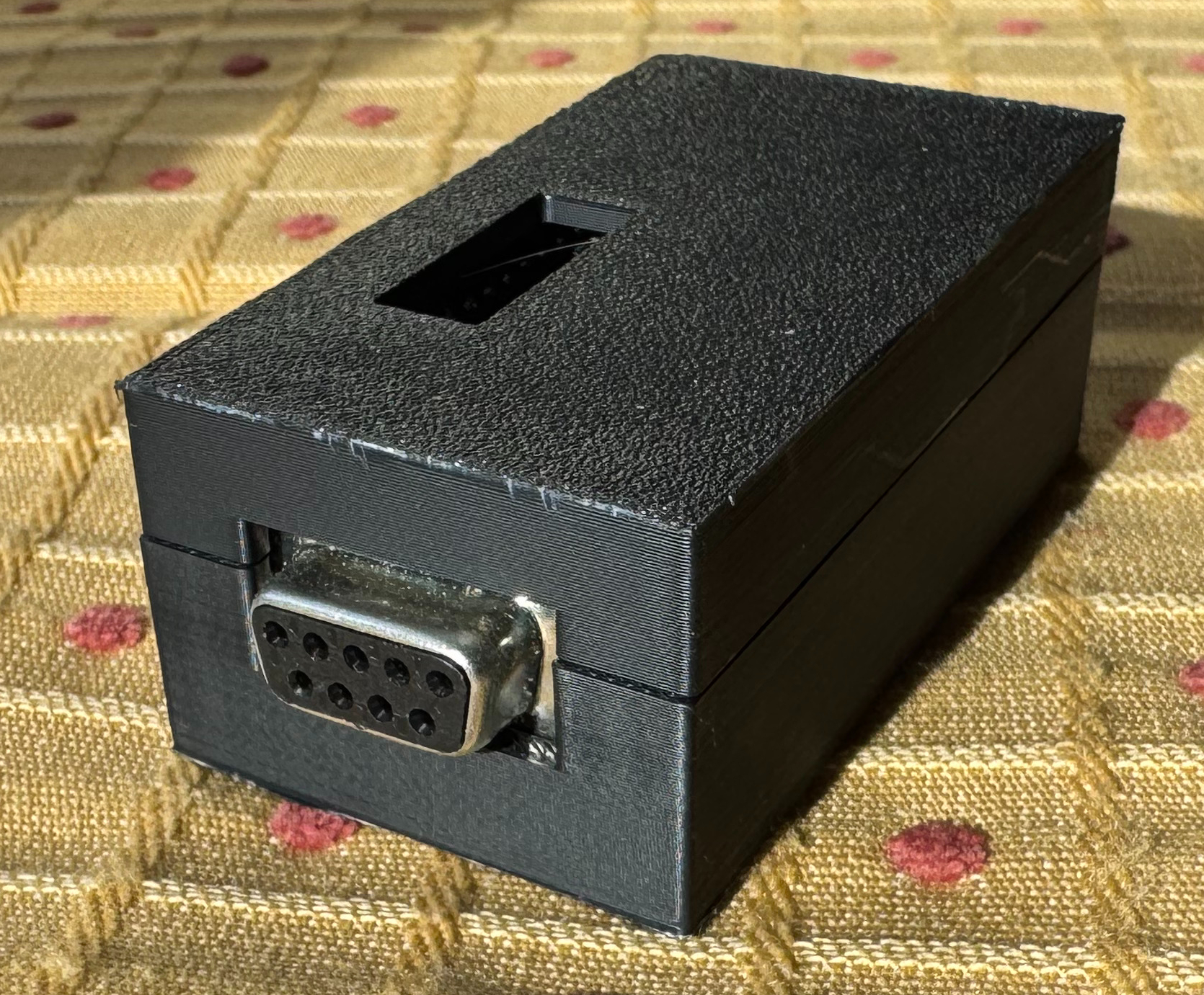
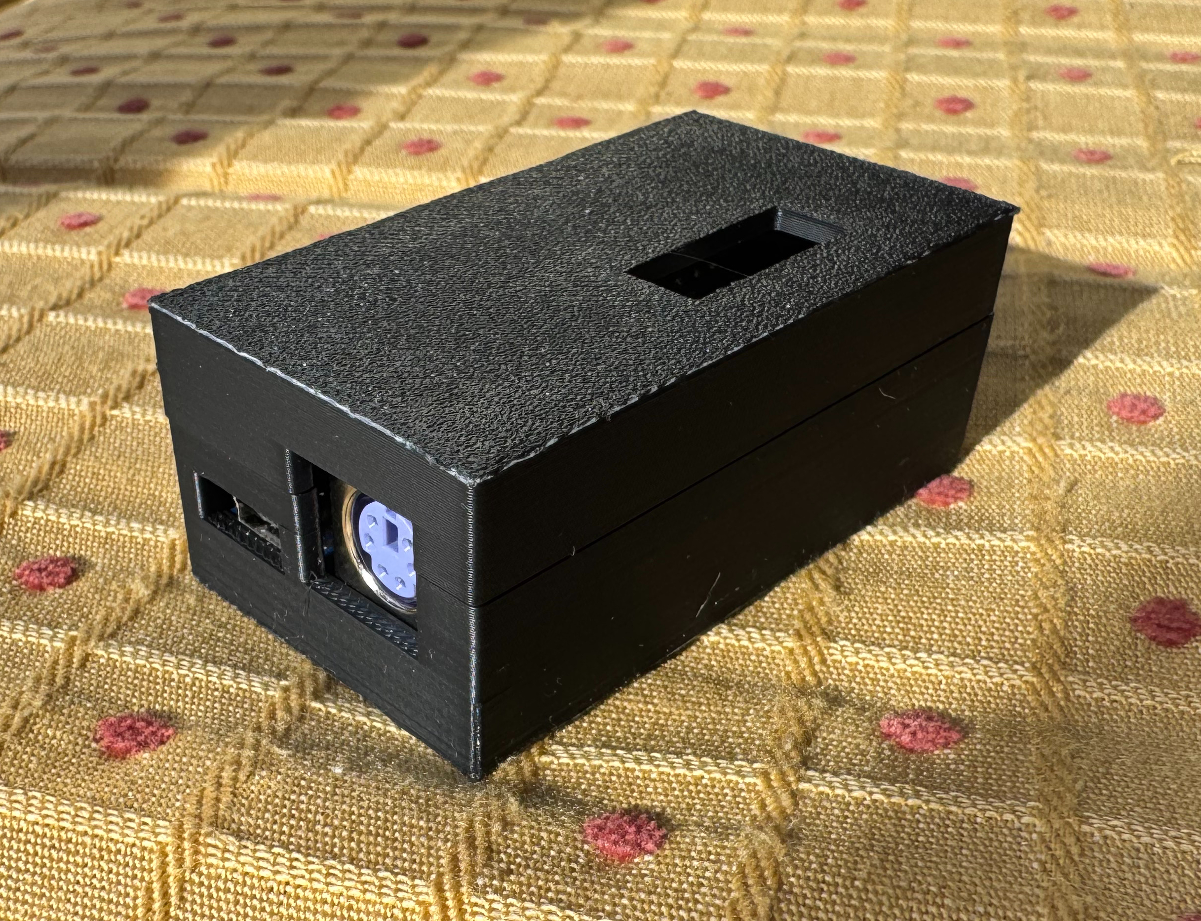
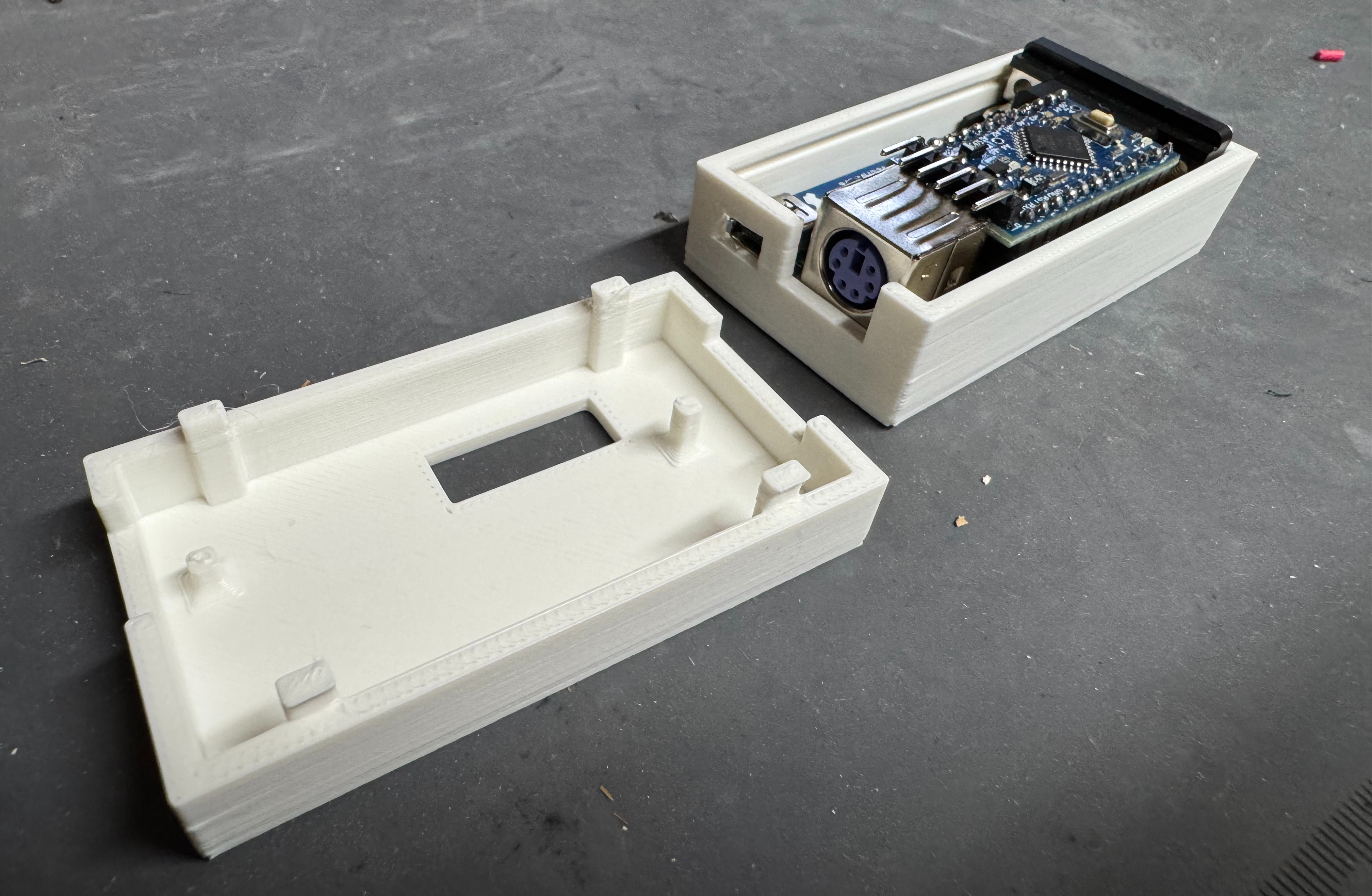
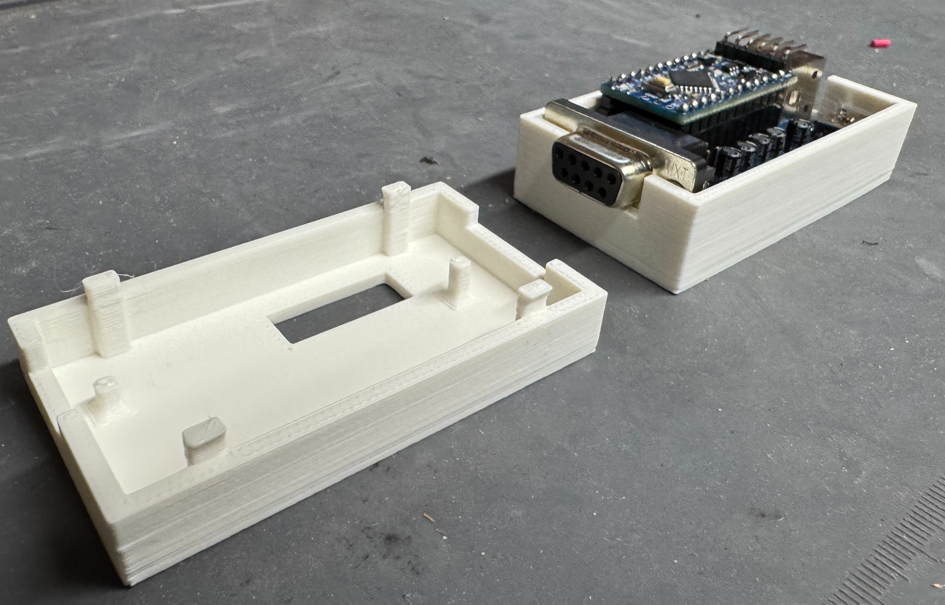
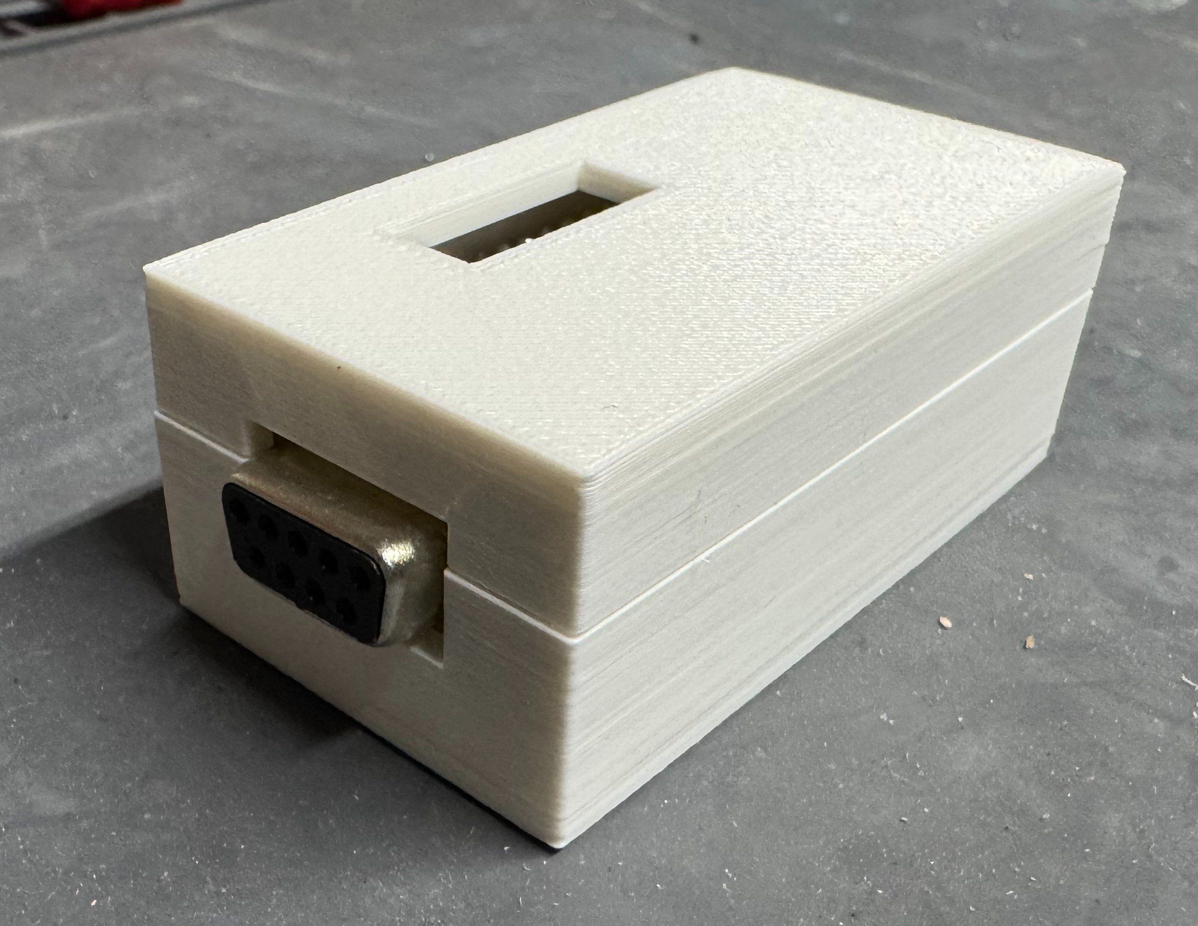
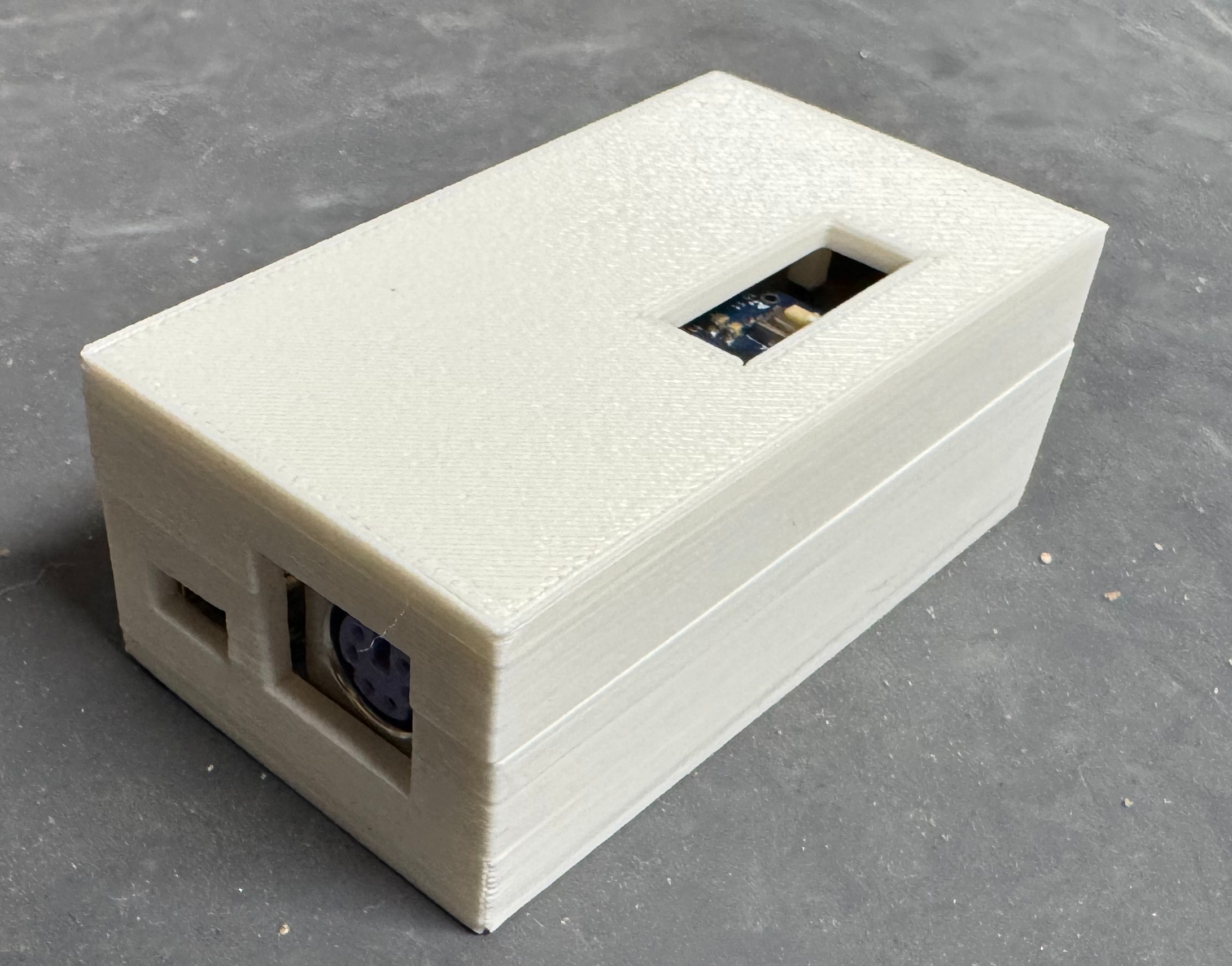
This is a device I will keep behind my old PC, and I didn’t want it to be a raw circuit board. I didn’t see any cases to 3D print, so I put one together. This was the first time I made a case that used little feet to snap the top and bottom half together; no screws! I also put little towers in to hold down the PCB in place. It took a few revisions, but I think came out nicely. There is also a little window to hit the reset button if needed. The black case was the second revision, the white case is the first.

Model: https://thangs.com/mythangs/file/1301661