The units themselves are laser cut acrylic. The front face that was put on the painted units was 3D printed. The designs for those pieces are on my GitHub page, https://github.com/daberkow/minimacparts . The original design was a tad bit smaller than the final unit. I ended up making it exactly about 1/3 scale, then realizing that there was not a screen on the market to do what I wanted to do. When I moved up to the 4″ screen, the resolution went up to a incredible 480×320. There were a bunch of issues around that resolution that I will get into in a later article.
For the Raspberry Pi I used a Raspberry Pi 2. The first version I made had a Pi 1 in it, and I ended up upgrading to the 2 just for the speed and added cores. With the system running a emulator, core 1 can get used up by that; having more available made sure things like SSH didnt lock up.
I designed two brackets, one set that holds the screen in place, and another that mounts the Pi to the inside of the case. The screen mounts are just two bars that are the exact with of the screen and help mount it inside, while leaving the port available for the IDE cable. The mount for the Raspberry Pi made it easier to take the Pi in and out of the case when building the unit. And a nice list so the Pi doesn’t get glued or screwed right into the side of the case.

For the front USB port, I got a USB 3.0, 6 inch cable. The most important part of this cable is finding one with a 90 turn at the end that does not stick out a lot. The Raspberry Pi is mounted in the end to the side wall of the case, and there is not much clearance. A USB cable that comes out from the top of the Pi is better as well. I ordered the wrong one for this last build, and then had to bend it a bit so it wouldn’t push against the side of the case.

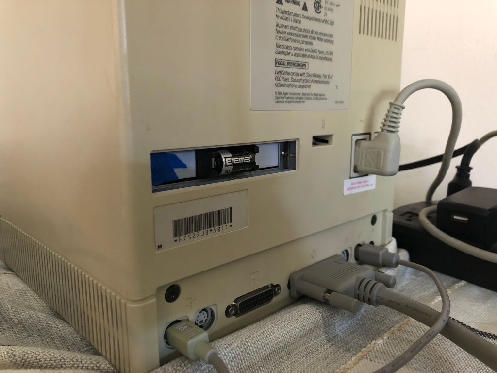
A simple micro-usb extension cable was used for powering the Pi. The female jack goes to the back of the case, so that the unit can be powered. Again, the 90 degree male plug was important because that side sits right next to the screen. Audio was a random 90 degree 3.5mm extension cable off amazon. The first unit, the clear one, had a different make than ones i got later. Some of the later units had a splitter instead of a single extension. The original idea was to have a speaker inside for the start up sound. That quickly added to the complexity and was cut from the final project.
The networking port was important so that I could easily add new programs to it. The systems also had a tiny wifi receiver, but I figured hard wiring was also easy. That was a custom keystone jack to a RJ45 port.
I mentioned in Part 1 that the screen was connected to the Pi via a IDE extension cable. After looking around for other solutions that worked cleanly, this was the best one. The cable can handle the frequencies, and was easy to find. It also doesn’t do any flipping of pins or roll-over shenanigans.
To bring it all together, super glue was used, not the most glamorous, but strong and holds. I made a few little tools to help me try to put better right angles together when gluing the cases. Those didnt always work out great.

To wrap up, I will go over my build order, just in case anyone decides to try to make one of their own. I would first get the front piece, and glue that to the side walls. Let that dry for a few hours at least, superglue likes to dry fairly fast, but I wanted it to be solid through and through. Then I would add the bottom front panel area, and the sliver that goes between the front bottom, and that bottom panel. After I put the bottom of the unit on, I would stop working on the main body. Now its time to get the screen, with it powered on and working with the Pi, line it up to where it looks good in the cut out.
After I have found the spot the screen should go, put the brackets on it, and glue it into place. This has to be a little carefully done, any spare glue that drips into the screen can make it look bad. Once the screen has dried, getting the mounting arms for the Pi bracket, and gluing them in place was done. There is not a real science to where it went, I would put the whole Pi sled in, then see where it seemed to work well with all the cables attached. Then sharpie those spots and glue the arms down, watching them long enough to make sure they didnt fall over. Once that was done, and I felt good about where the Pi was, I would glue two tiny blocks I 3D printed to hold the Pi sled in place.
Gluing the front USB isnt too bad, its putting it in position then gluing the edge of the extender into the place it should sit. The hardest part is not getting glue in the connector, and doing multiple layers so that it doesnt move with normal user use.
Getting the back to stay in place was my least favorite part. There are little L brackets I 3D printed that the back could screw into. They work well but lining them up and gluing them into place, and not the back itself was tiring. I would tighten the brackets a fair amount to the back plate, then get the plate into position and glue the bottom two brackets into place. Then I would do the top two. At this point gluing the different connectors into the back ports isn’t too bad. I also made brackets for them, the brackets are bigger than the whole so that it covers the whole port when the piece is in it. These brackets weren’t held with little arms like the Pi, just glued into place.
Finally the top was glued in, and then the last little top slant area. The screen I mentioned getting before may not be available from Amazon, but there are a ton of others that are all seem to be made by the same place, then had another brand stamped on them. For the last build I did, I grabbed another brand (link) and it worked with the same drivers out of the box.


