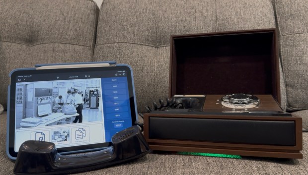
Periodically I enjoy doing more artistic electronics projects. I wanted to capture more of the family stories I hear but aren’t recorded or written down. I had the idea to get an old rotary phone, remove the parts inside, and replace them with an ESP32. When this phone is dialed, it looks for a year that is close to the number dialed, and then plays the audio file from a family member telling a story of that year. Along with hearing the story, a companion tablet website would allow you to see photos and get more information about the story. As all my “quick projects” go, this has been going on for a while, partially because I grew the scope some, partially because getting recordings can take a while.
Along with everything below, here is the github repo that contains controller code, 3D models, scripts, and more information. I have had three hardware revisions; the first was a prototype, the second was the first phone that was overly complex, the third was a simple phone with an all in one ESP32 audio board. This project was a great way for me to play with the ESP32 using SD cards, audio, and even Wifi.
General Design
All the different versions of hardware have an ESP32, SD card reader, and an audio chip. The main inputs are on/off hook, and the rotary piece itself. Then for output we have the speaker in the handset. When the handset is picked up, we play a dial tone.
Historically I have used the Arduino IDE to develop embedded code, for this project I moved to PlatformIO. As a more advanced user its MUCH nicer. You can easily add libraries, and do all your development within VSCode.
Outside of the dialing a year, I wanted some fun features that also helped with discovery. Dialing 0 runs an Operator audio file. This file is generated by a python script that scans the SD card contents, then creates an audio file stating which years can be dialed. Dialing 9 plays a random file from the SD card, this helps with random story discovery. Dialing 8 gives the option to change the volume, this prompt is created via another python script.
The rest of the numbers will try to find a year with a fuzzy matching a decade up and down. If no audio is found, it plays a busy signal. If the user doesn’t enter a number within 10 seconds or so, it plays a busy signal.
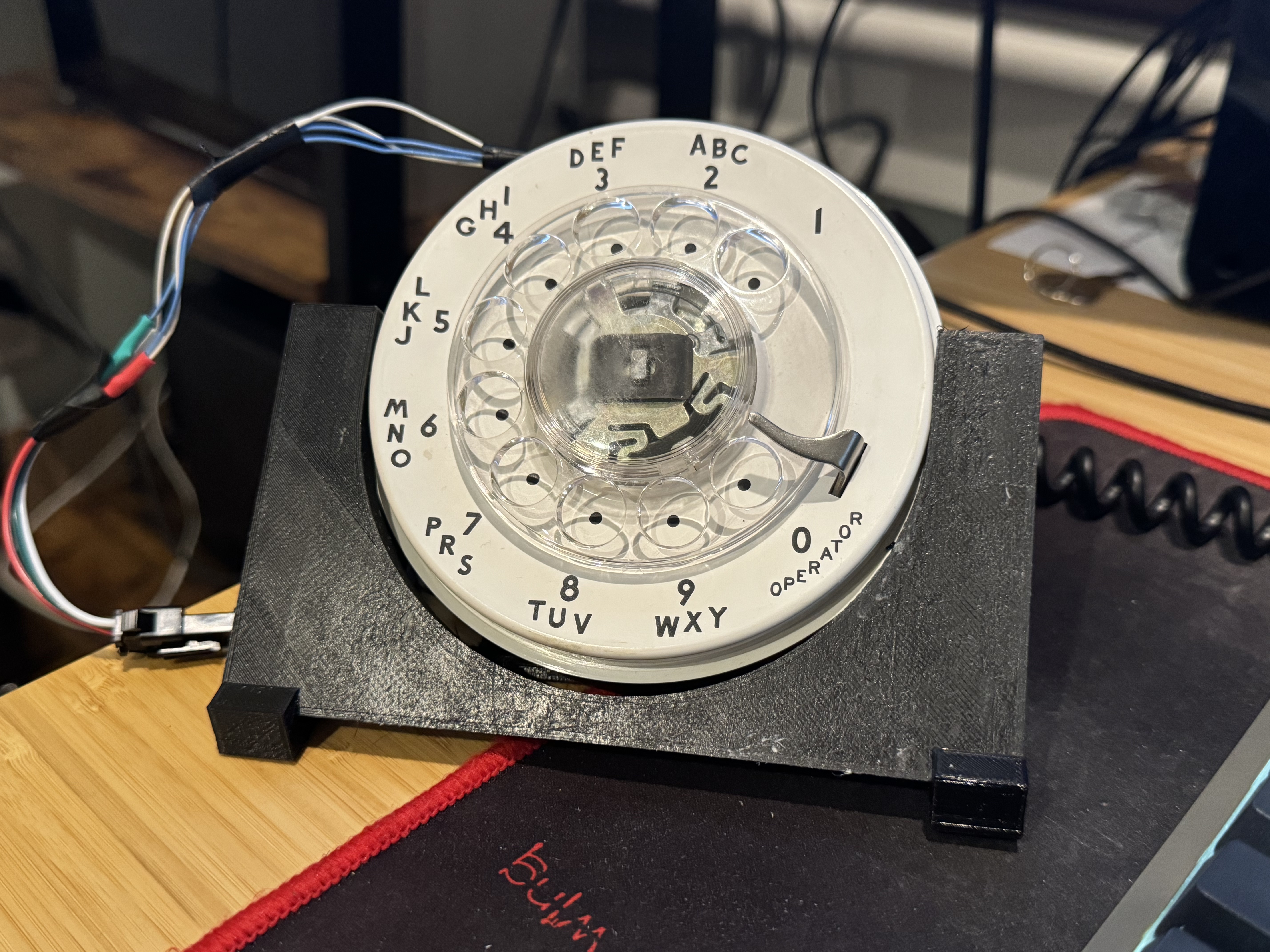
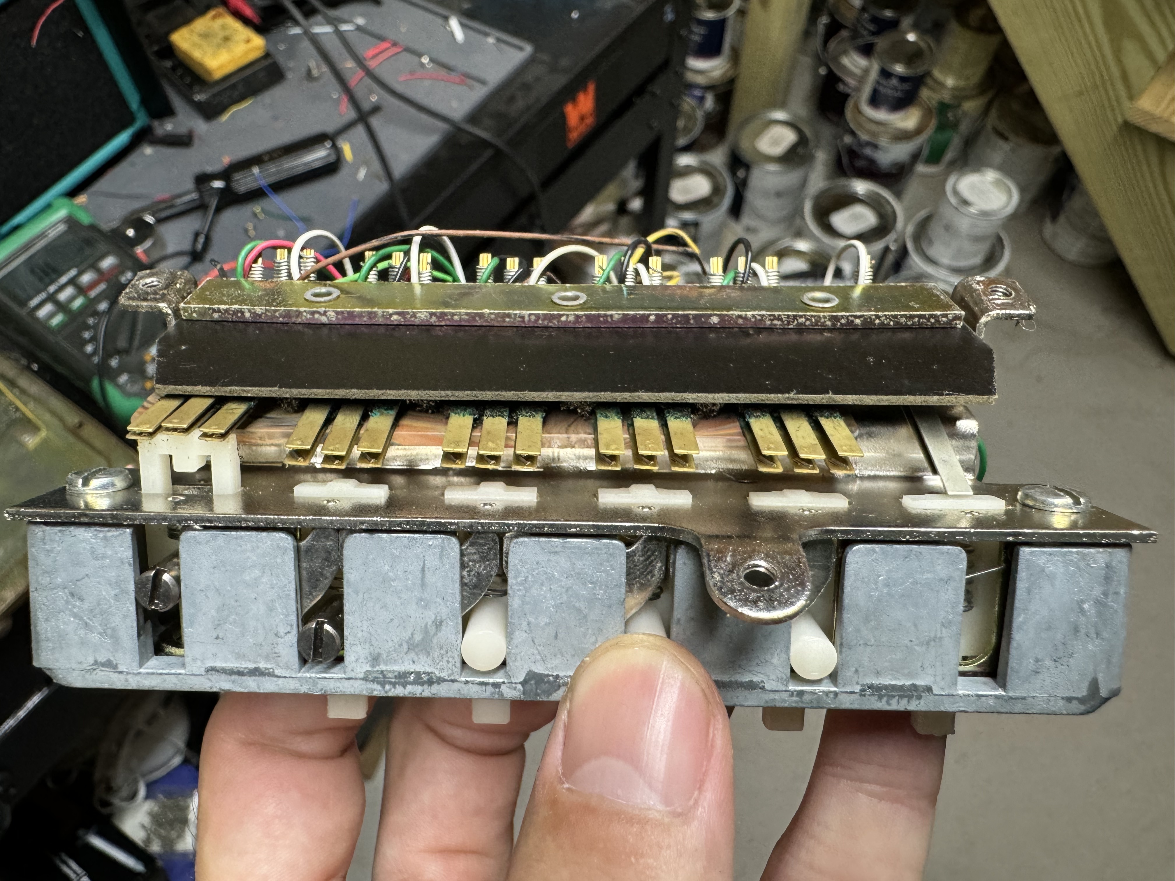
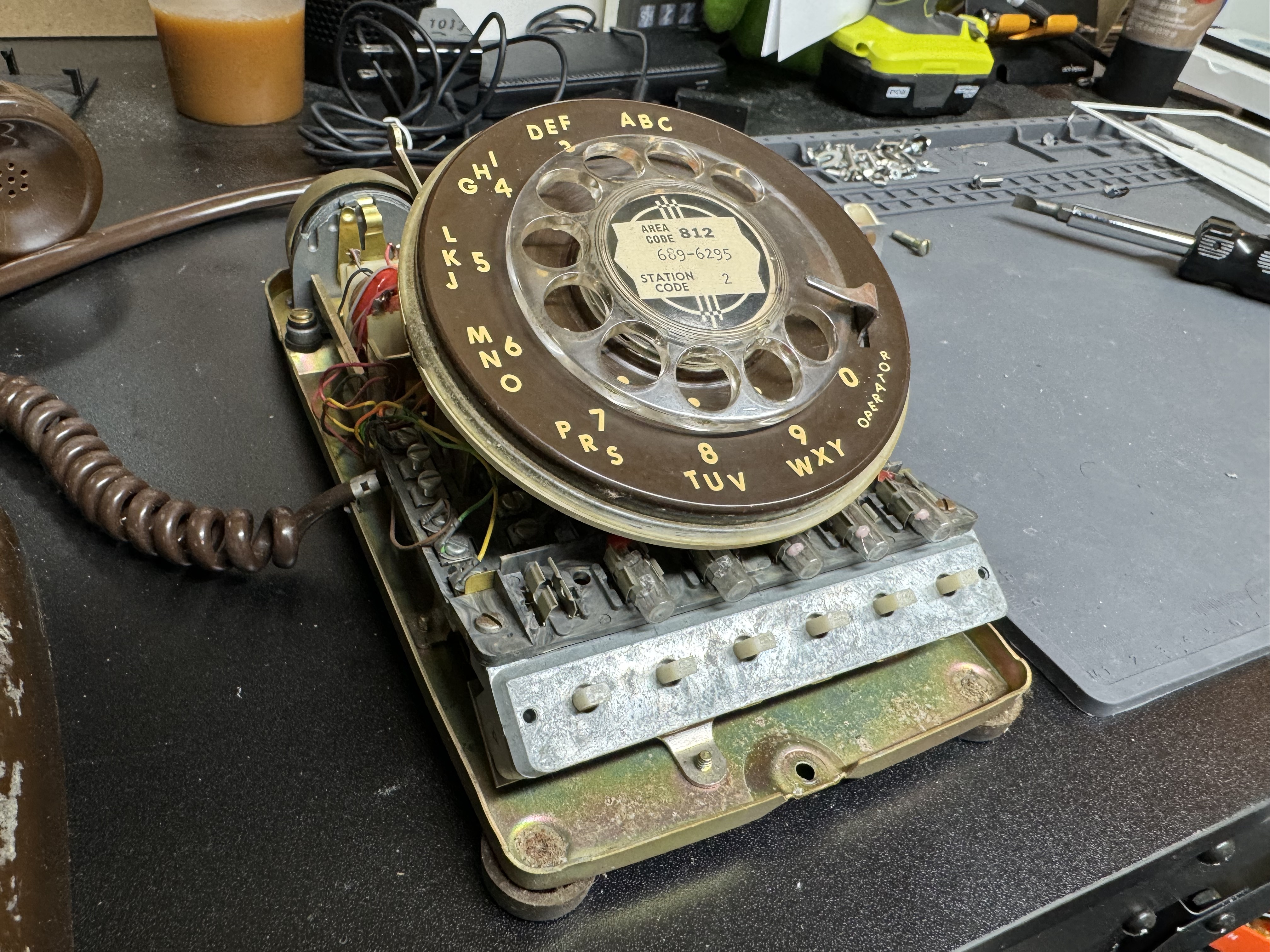
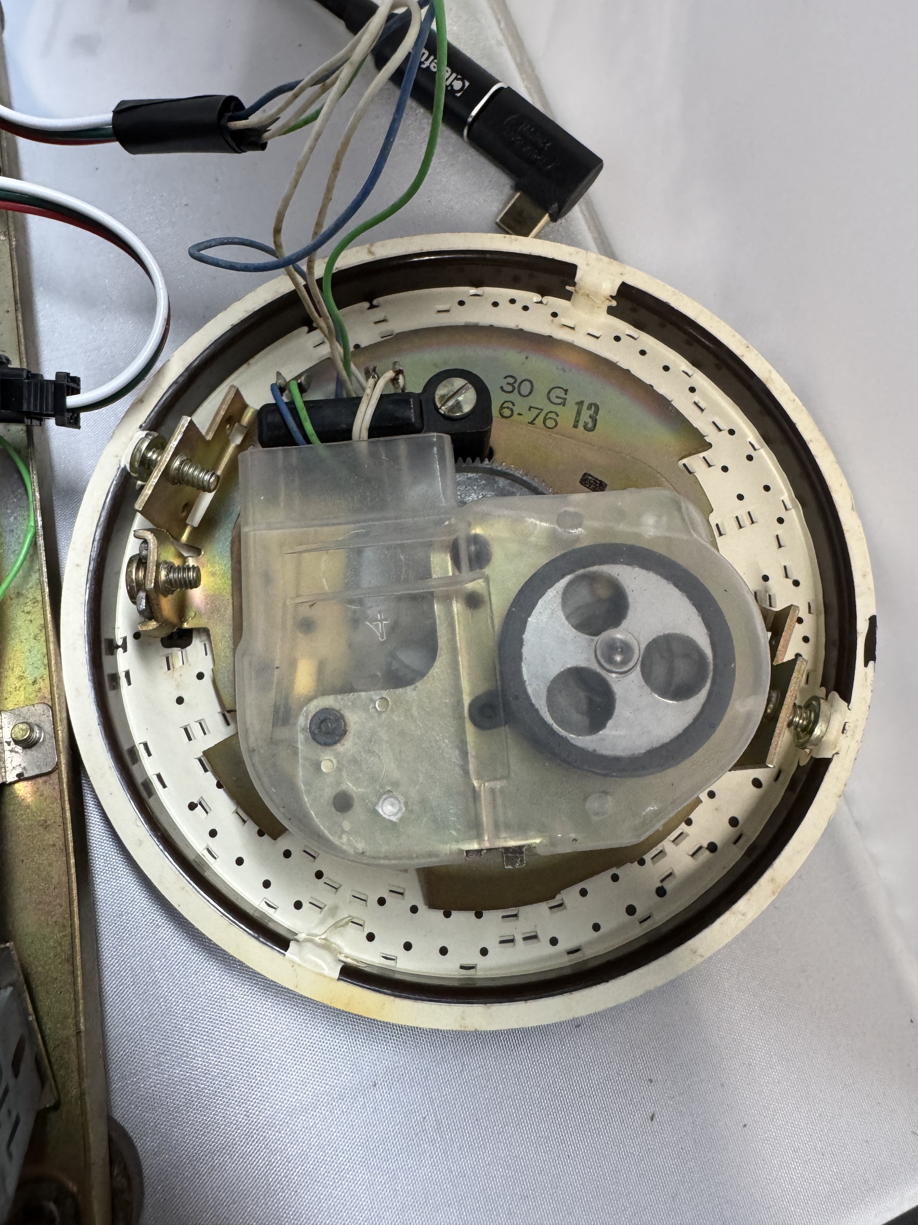
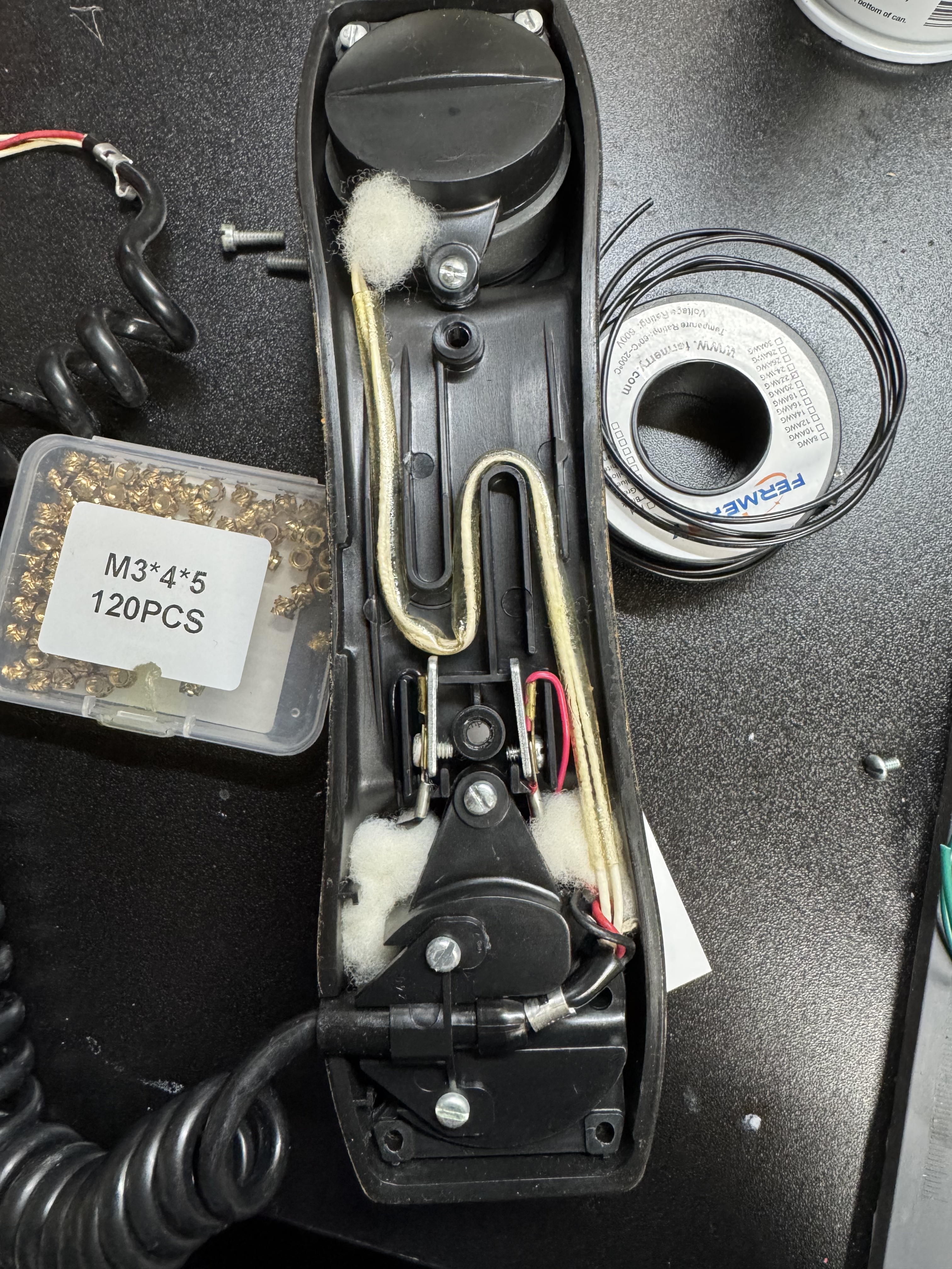
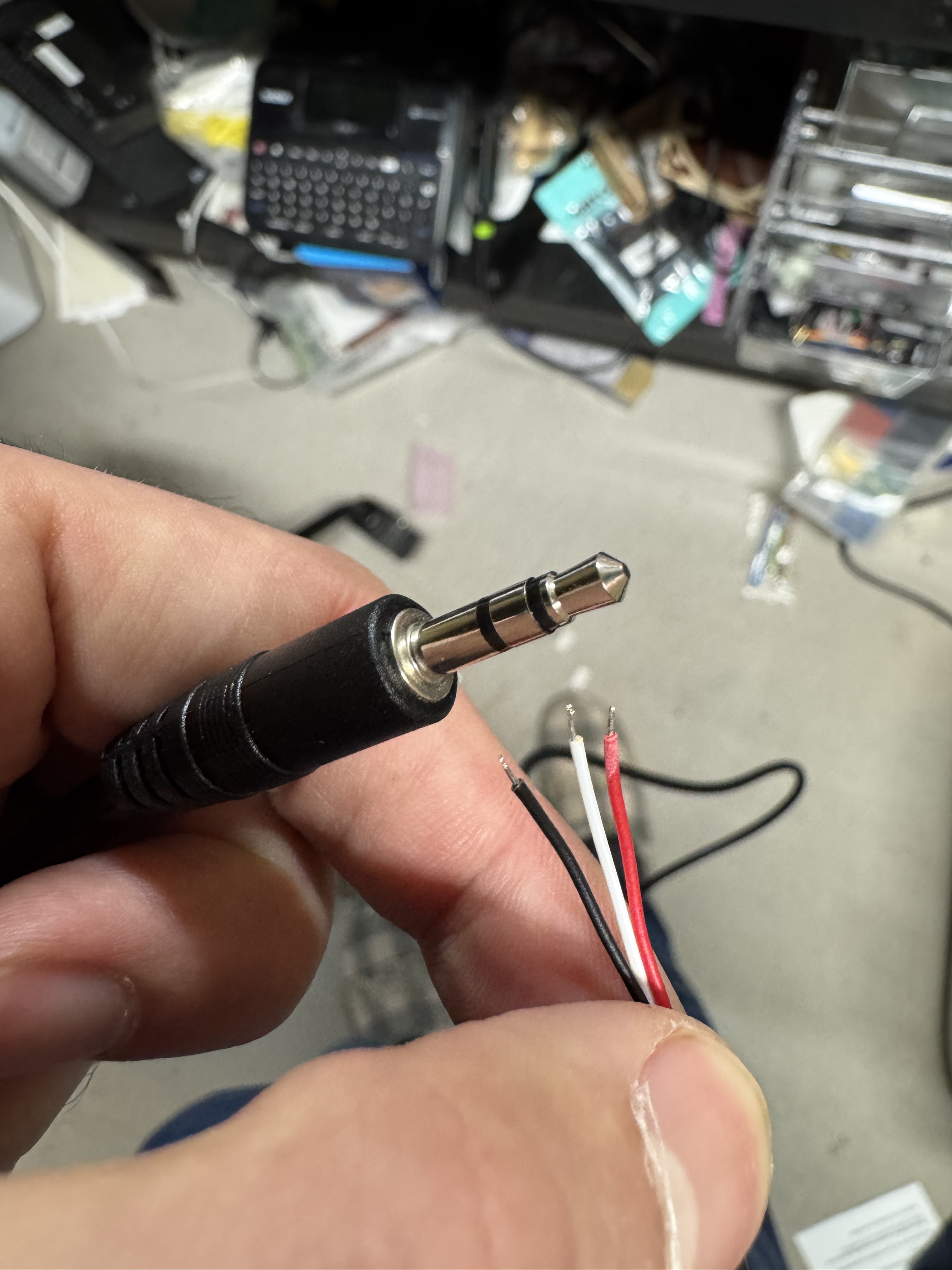
A quick tangent: the way the rotary dials work on these old phones is interesting. There are two pairs of wires that come off the rotary. Code for it is here. The first opens once the dial moves at all, this pair goes from a closed circuit to open and remains there till it rests at the start again. That’s when you start tracking the rotary. Next the second pair will pulse every time it passes a digit. The flow for reading this is once the movement starts, clear a counter and start counting pulses. It’s shockingly and happily simple.
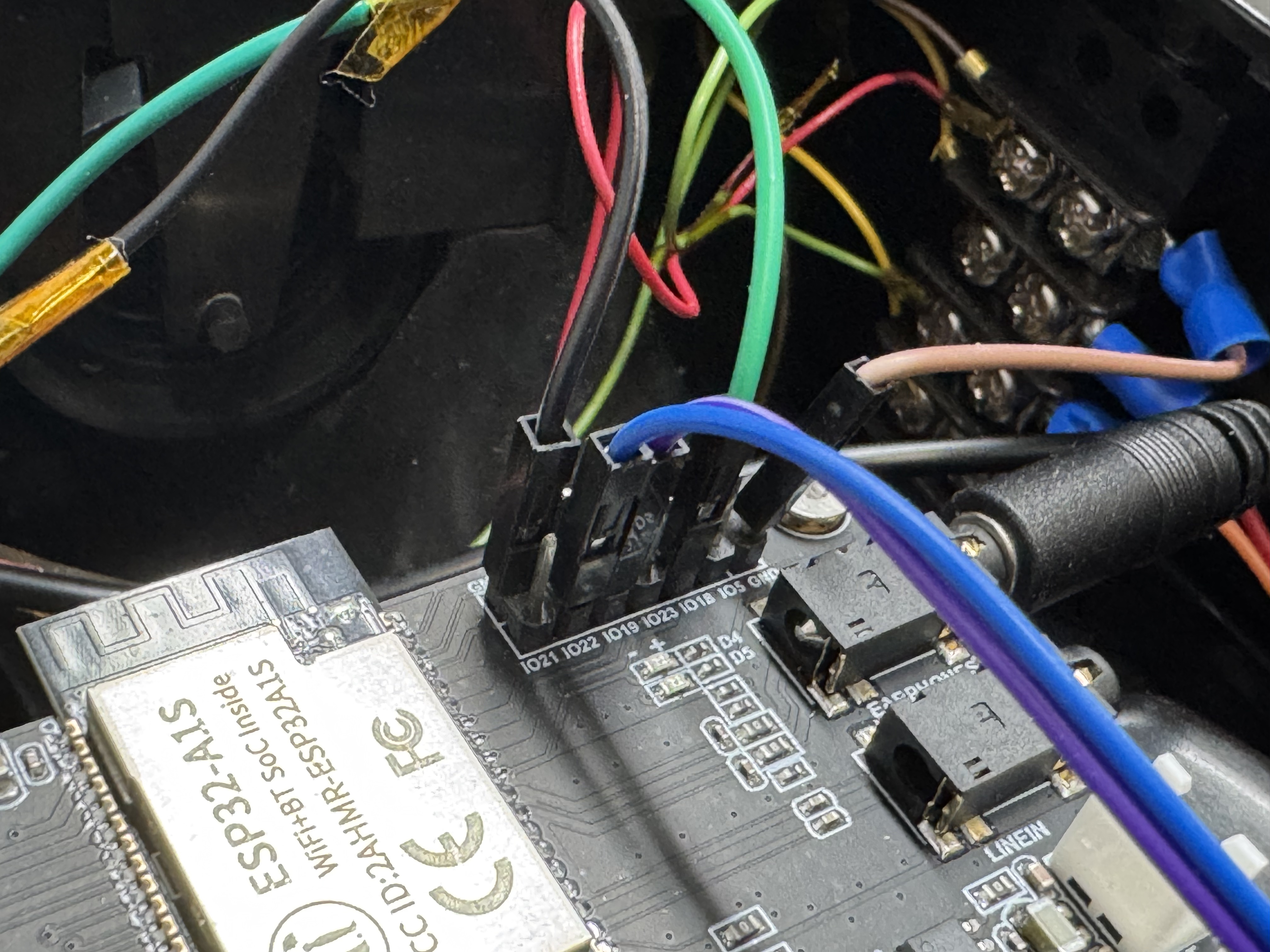
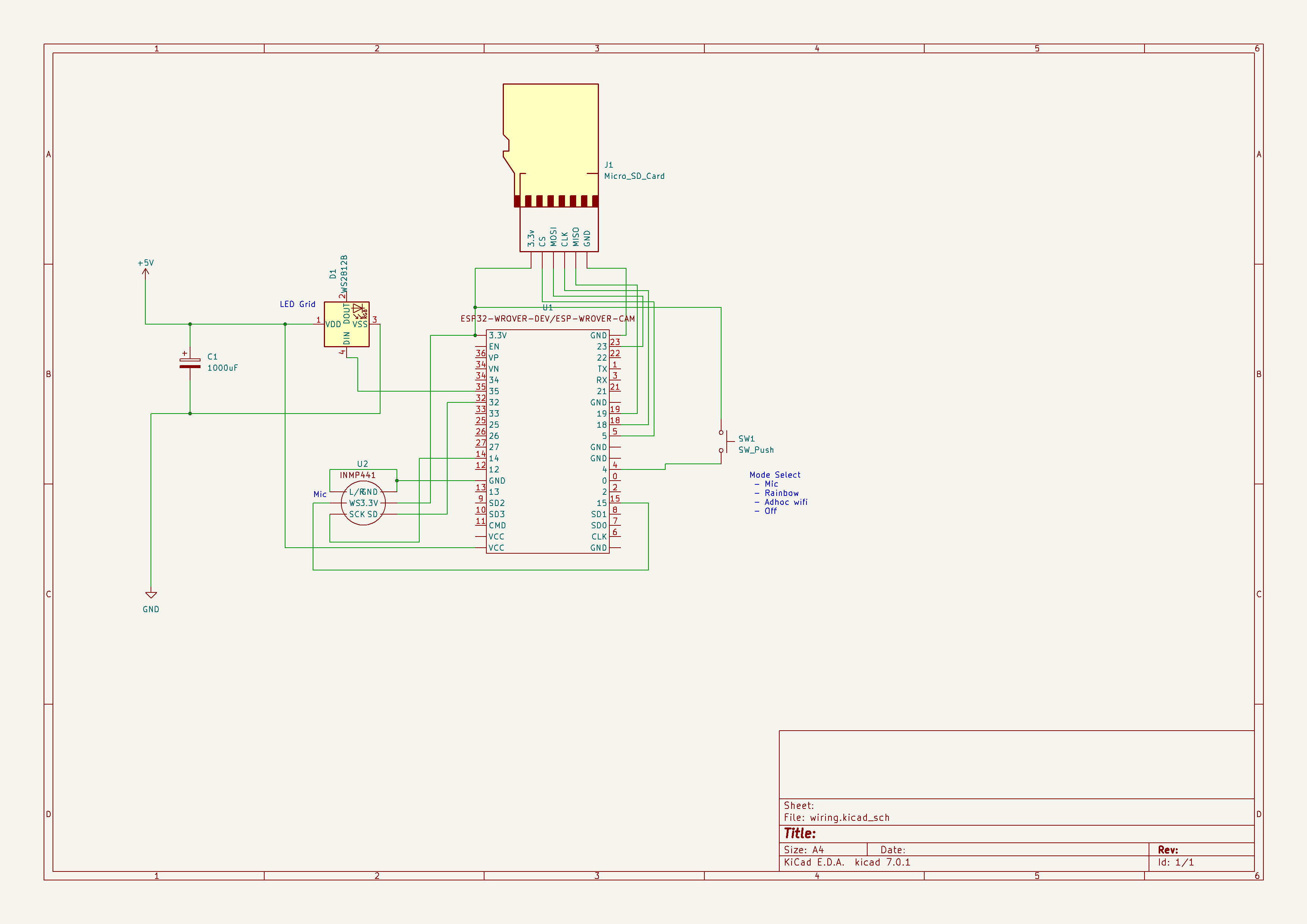
Pinout
Other than V1 which had all the buttons and front LEDs hooked up, the wiring is fairly simple. There is the SD Card, which is internal on the all the boards; I have done external SD cards before but I prefer to have my ESP32 boards have a SD card reader on them. Audio – headphone amp, internal on V2 board. Then the two wires mentioned for rotary, and 1 for hook on/off. That’s it!
Iterations
Prototype V0
This was my first test, I 3D Printed a holder for a rotary dial I got off eBay for about $10, and wired up all the parts I would need. For the hook I used a simple switch you could toggle on and off. I did not touch things like Wifi in this iteration, this was just to see if I could get the basics working. The rotary was around $10, then a $17 ESP32 with built in SD card reader, then a few extra dollars for a switch, audio amp, and speaker. Total cost was around $30. This was built in a weekend or so.
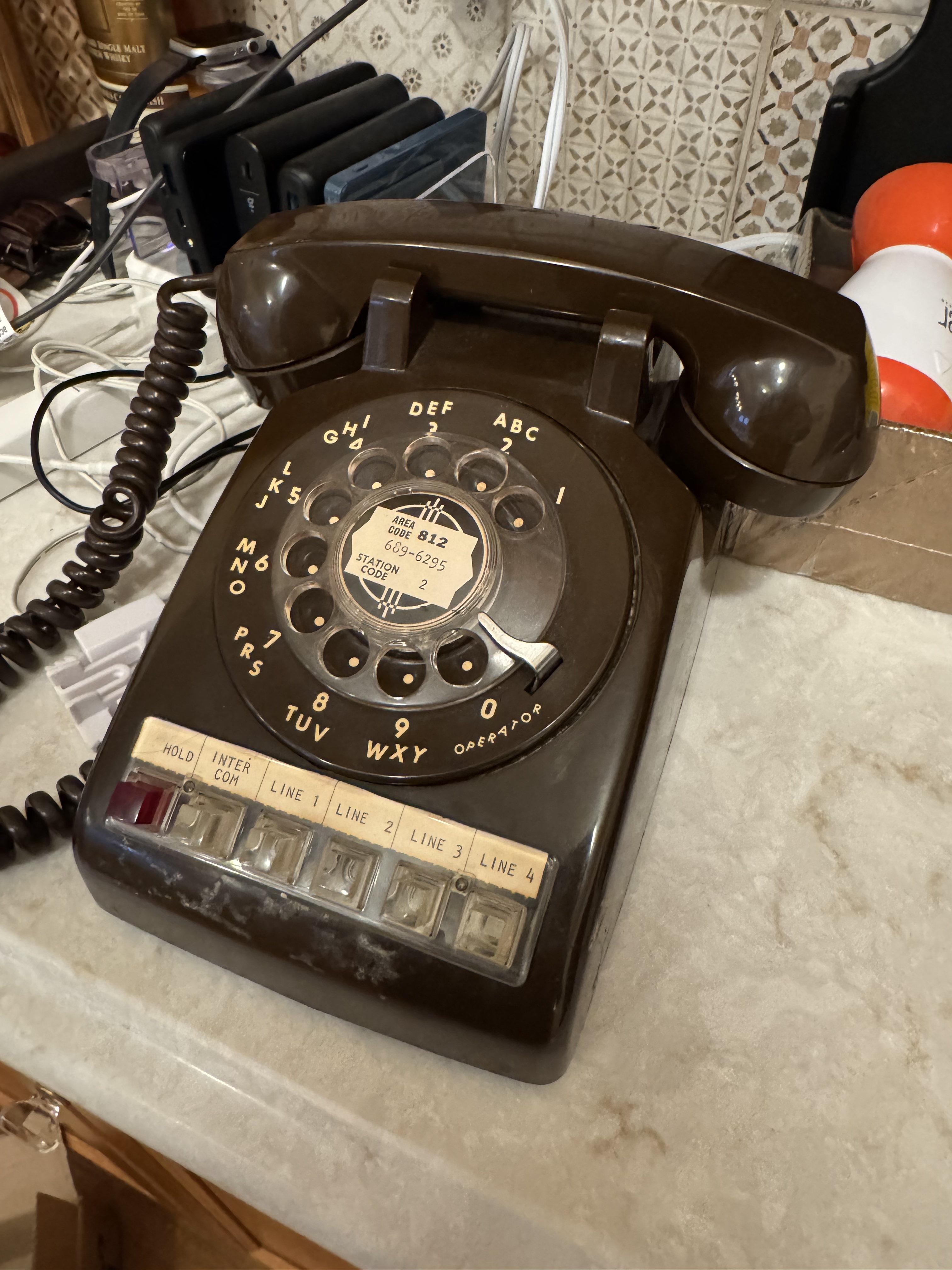
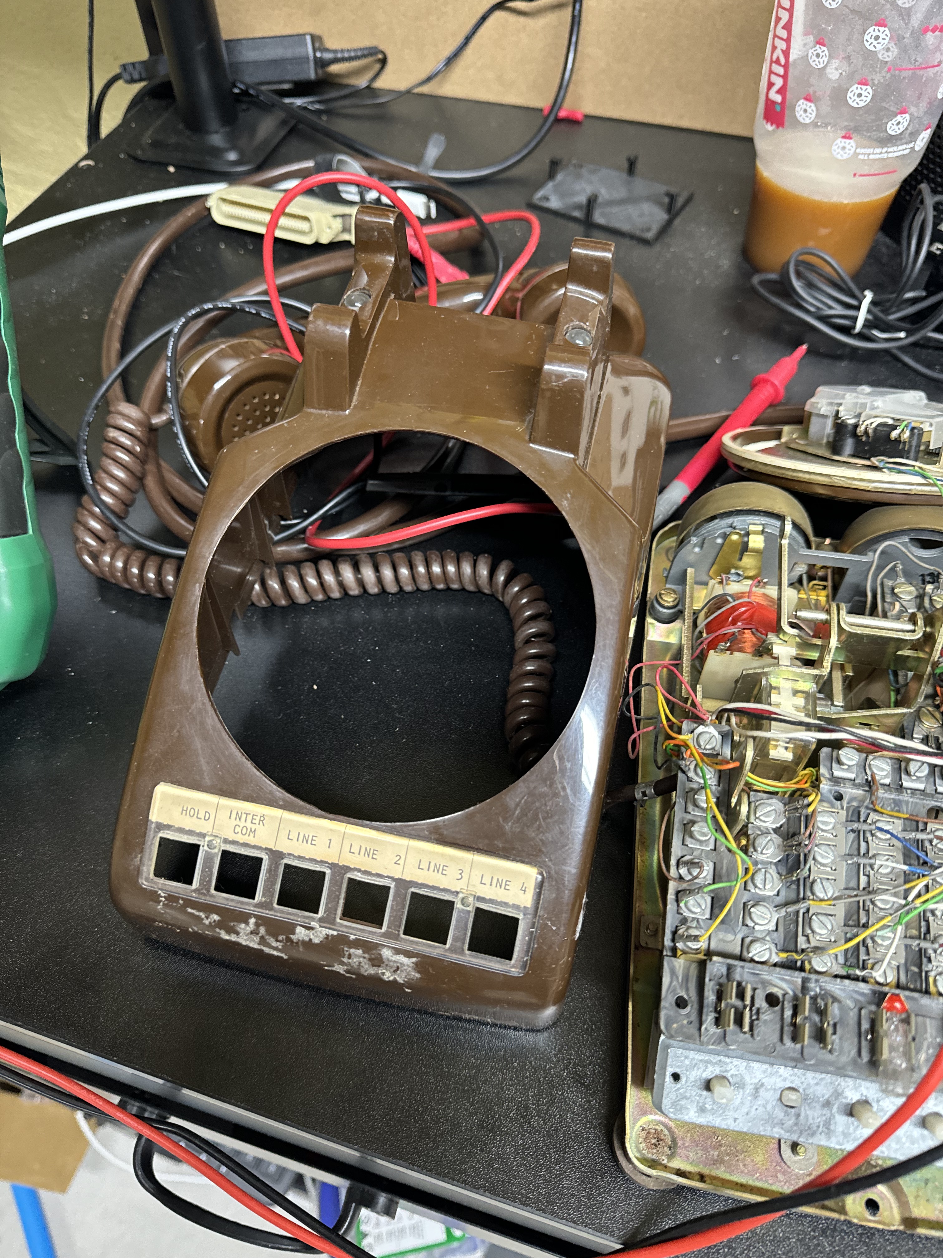
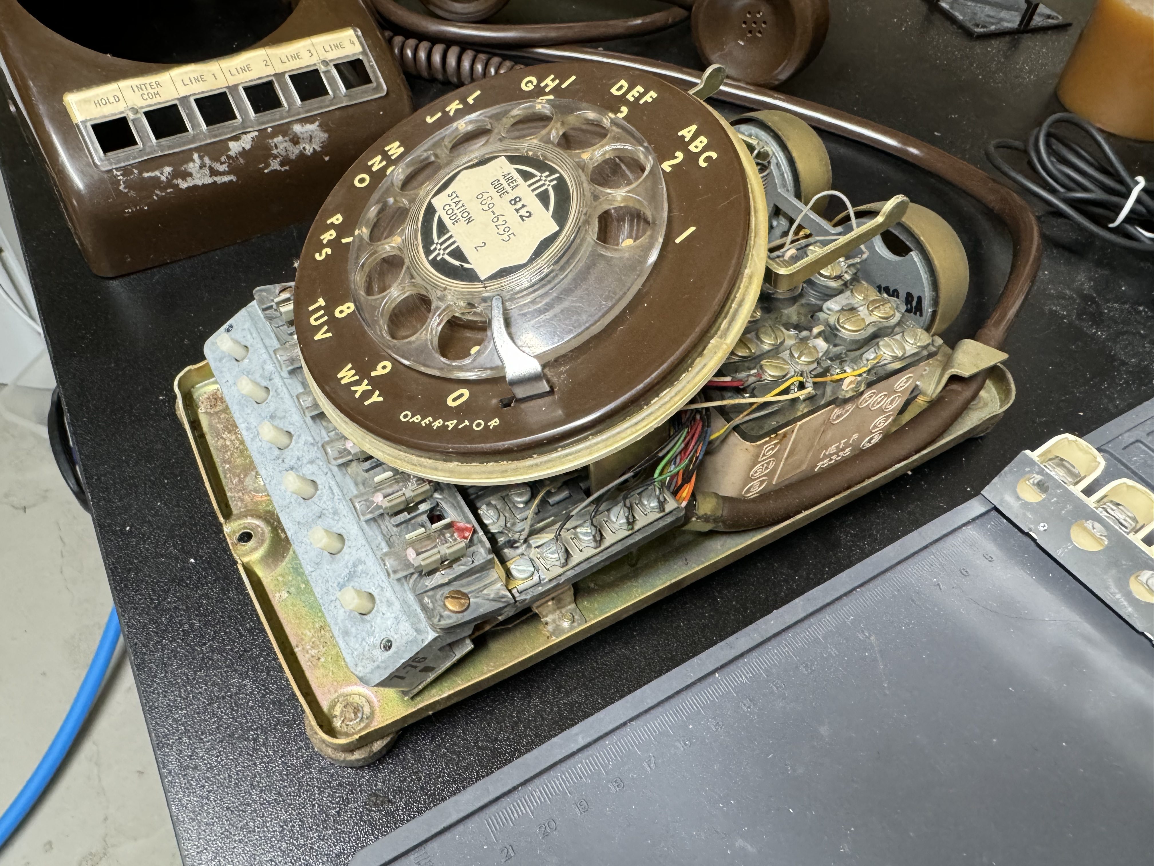
Phone V1
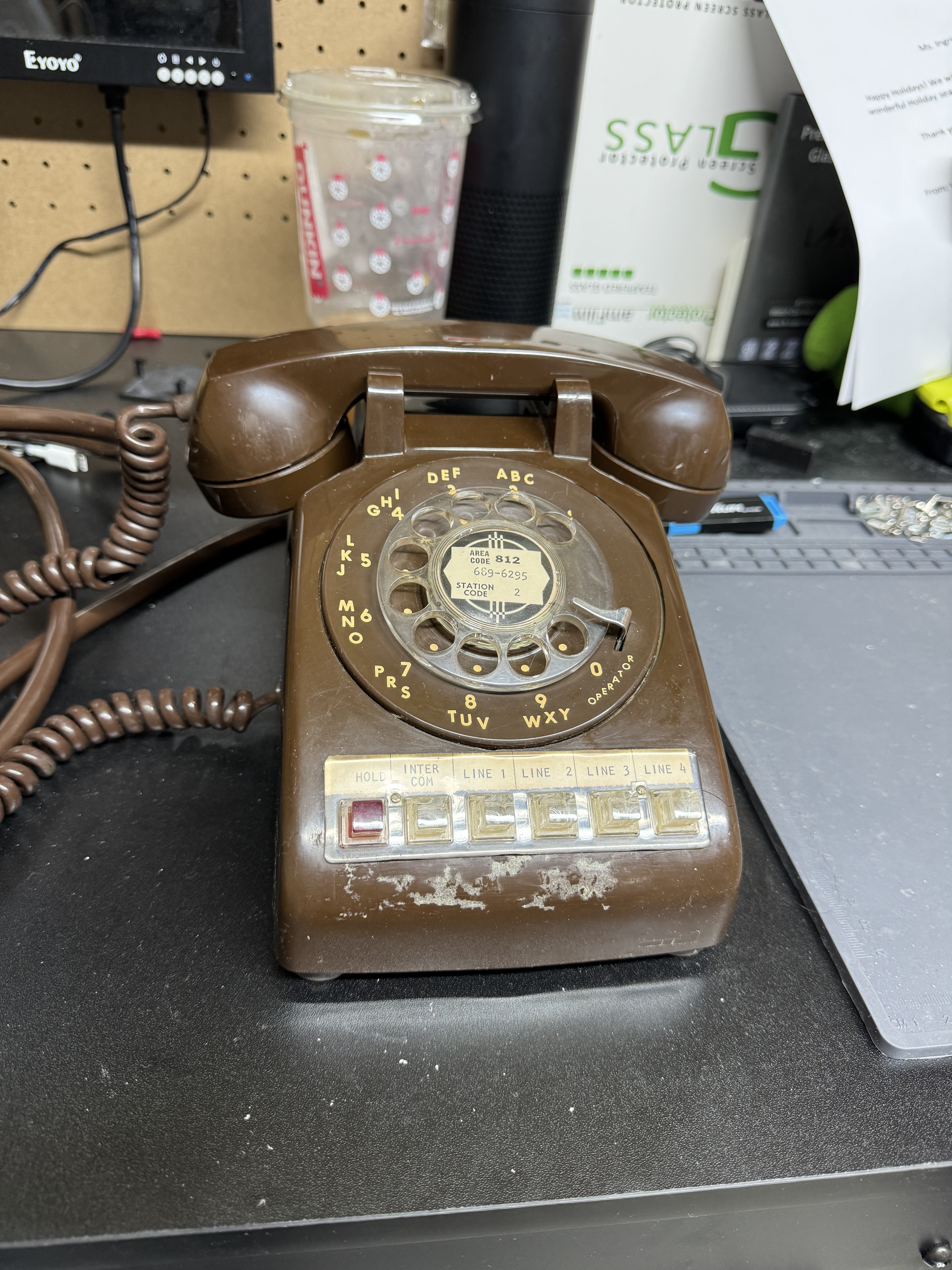
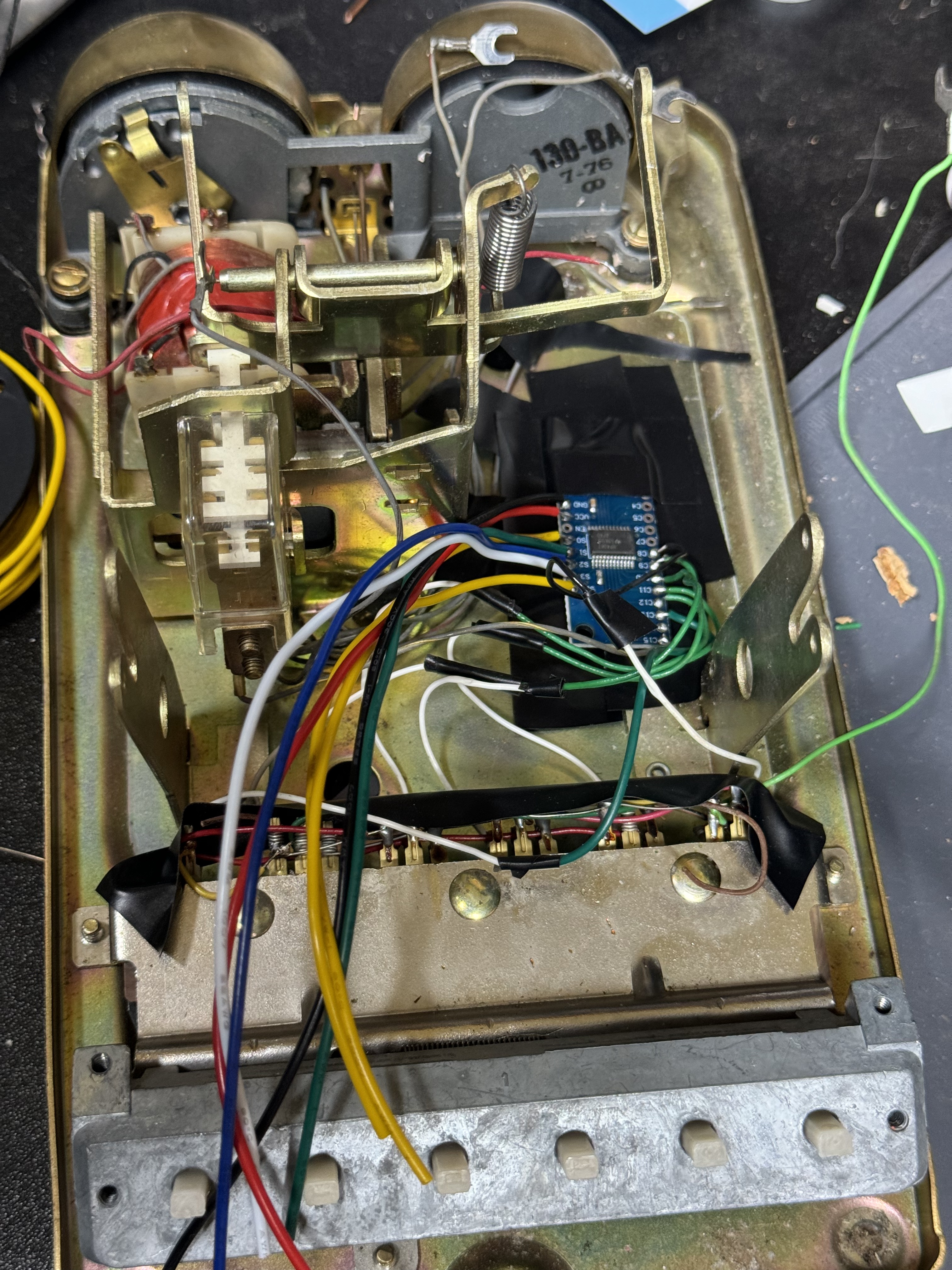
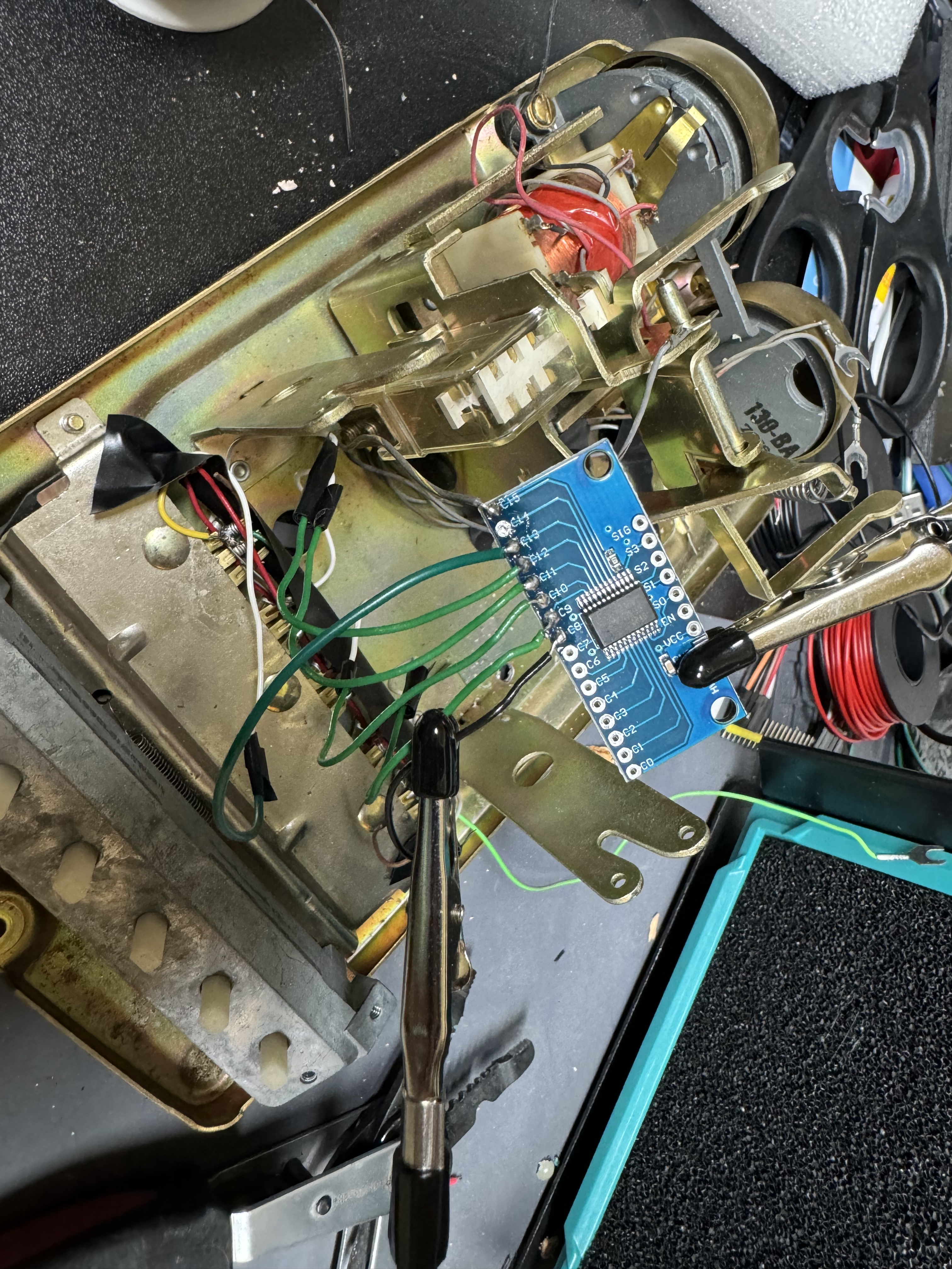
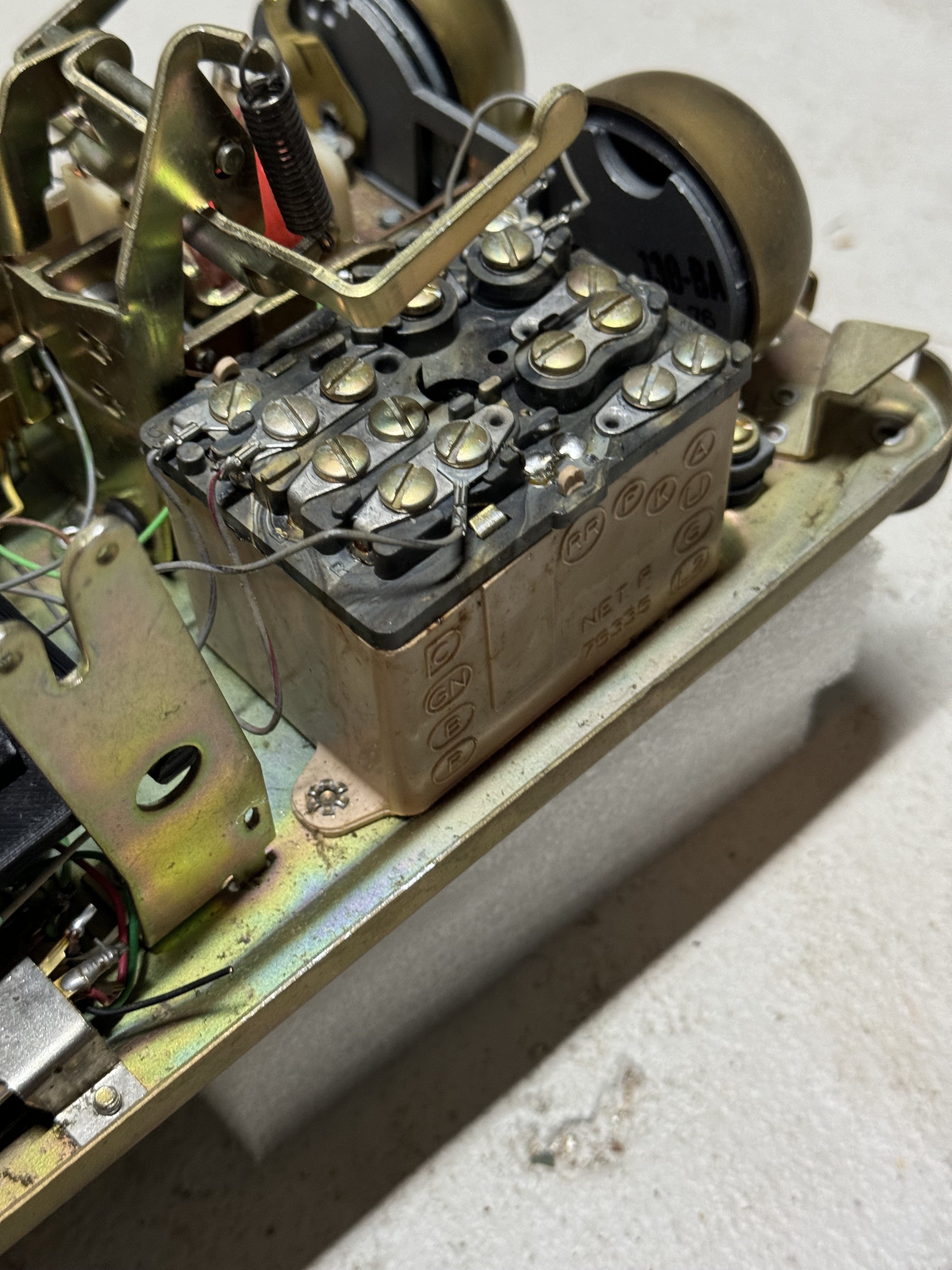
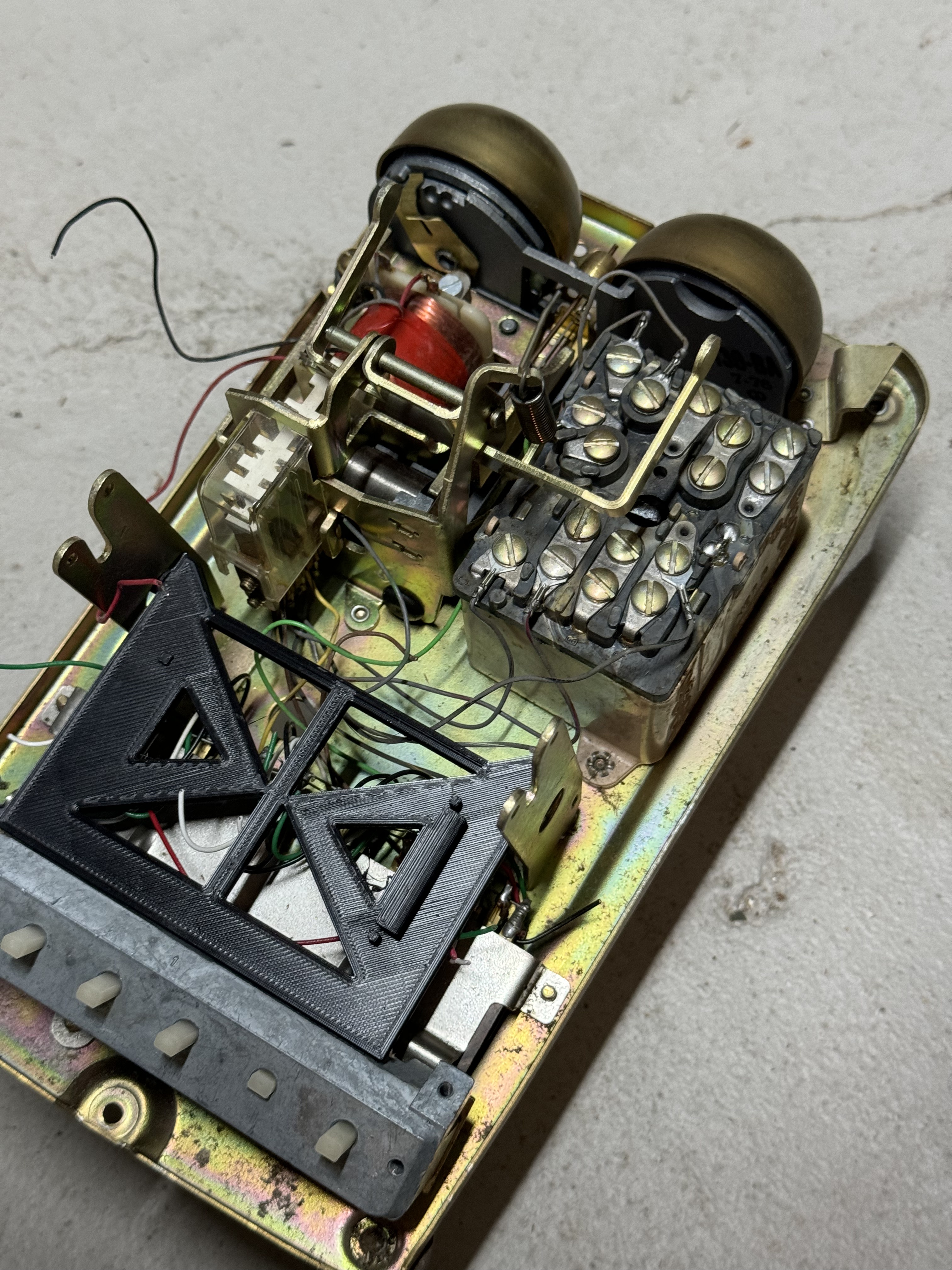
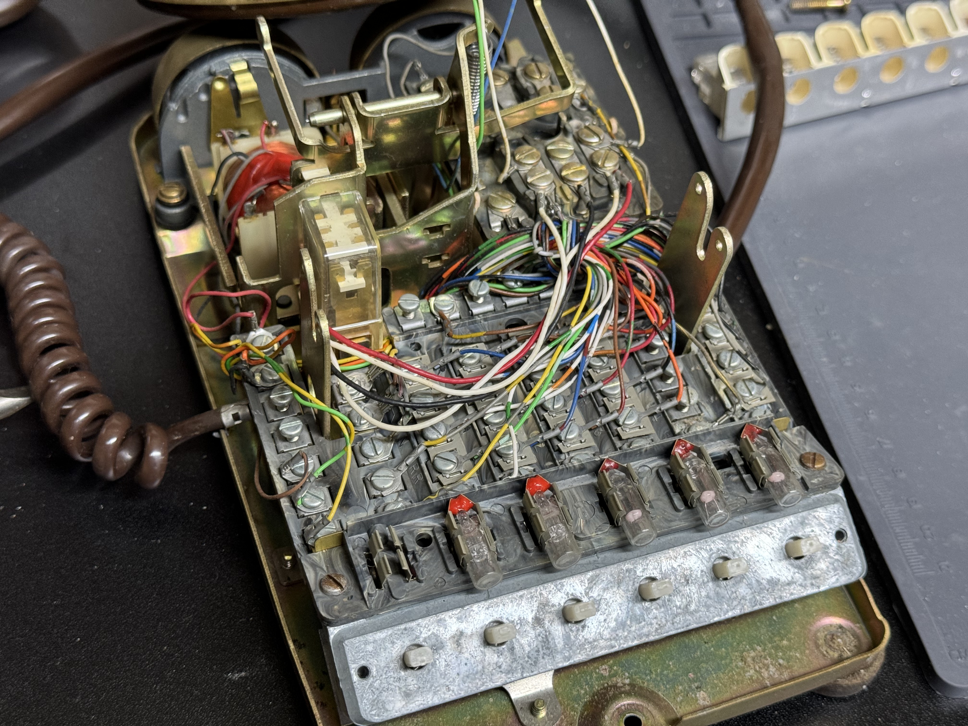
After I had the prototype working, I moved onto to getting a real phone, and trying to get everything working within that. I got this phone that had several lines, and I thought I would use those buttons for different functions. Over time this seemed like overkill and kept me from making more progress. I also needed more IO ports, and had to start using MUXes to do this, which further discouraged me. I wired up all the front buttons to have a LED behind them, and could read if they were open or closed. All I ended up doing was lighting up line 1 when the handset was picked up. The buttons do have a great tactile feel though.
I did do most of the development with this phone. I got the web interface working, and push many versions; which involved doing a static build, and then coping it to the SD card. I cut a hole in the side of this phone to allow me to externally mount the SD card. When the web pages need updated or I needed to load more content I need the SD card, and that is buried very deep in this version of the phone.
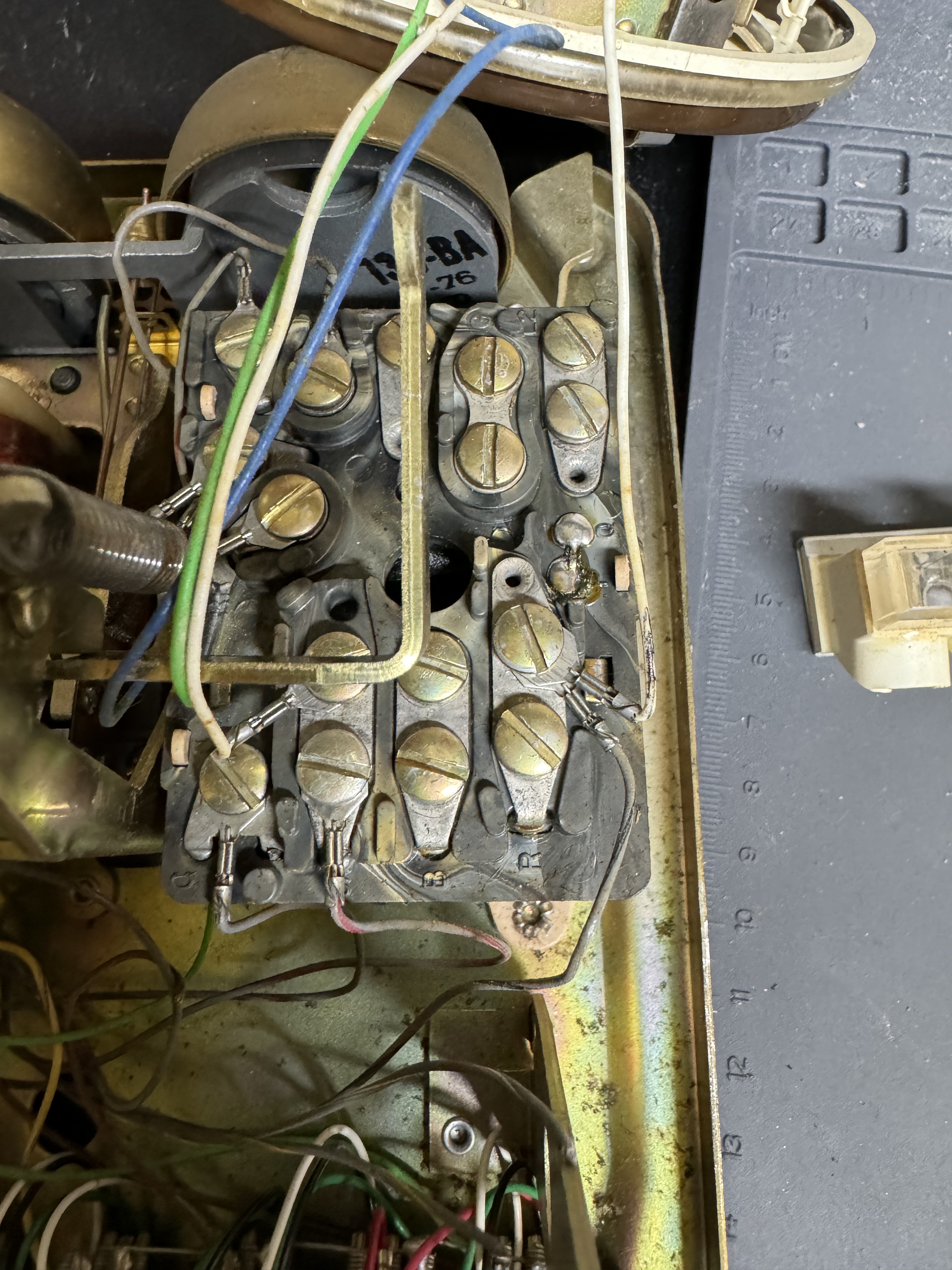
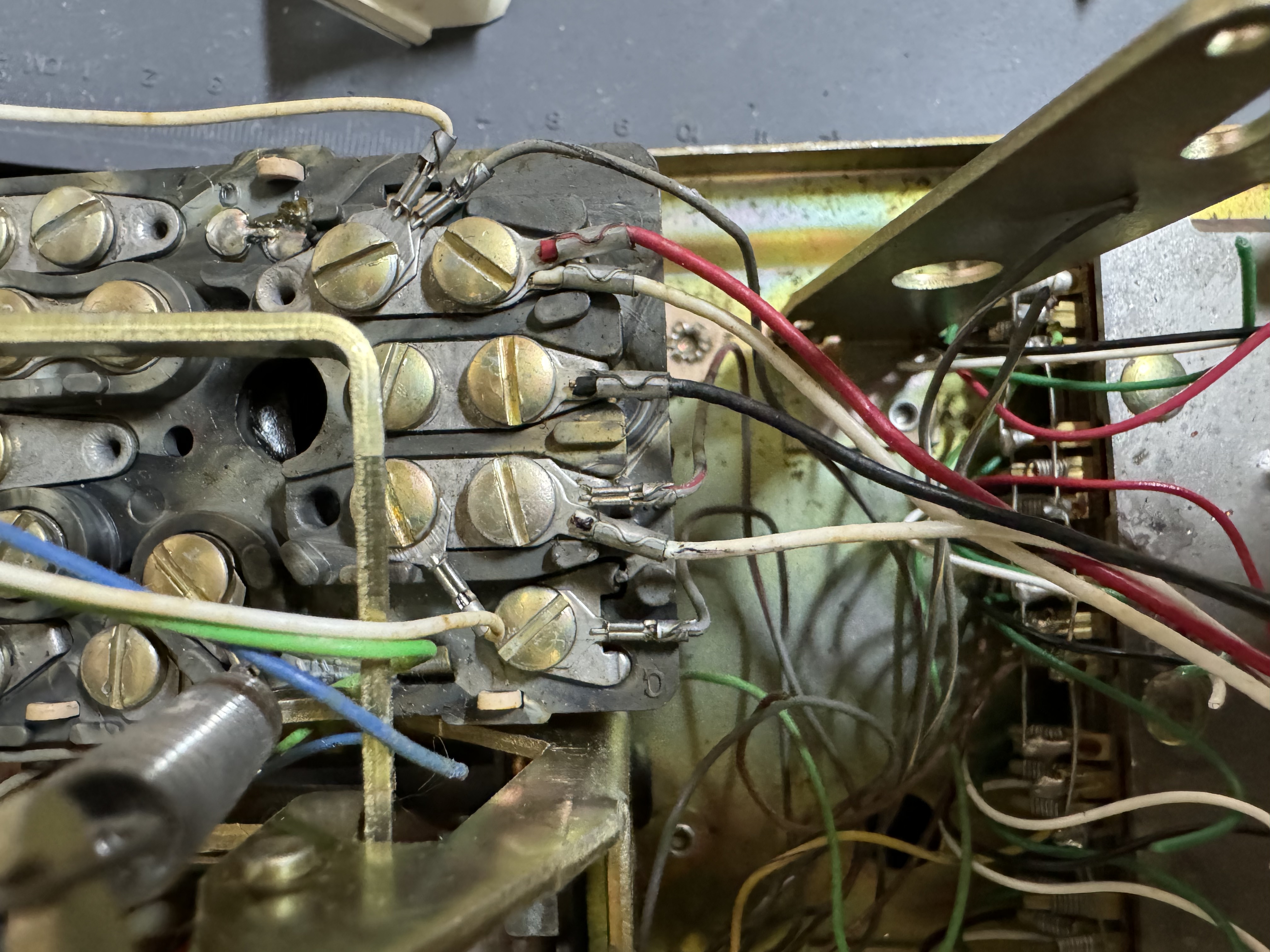
To get the hook signal, I connected to the old phones terminals that close when the phone is on the hook. This worked decently, except I added some code to take several readings and average them. I think the old contacts weren’t the cleanest leading to periodic bad readings.
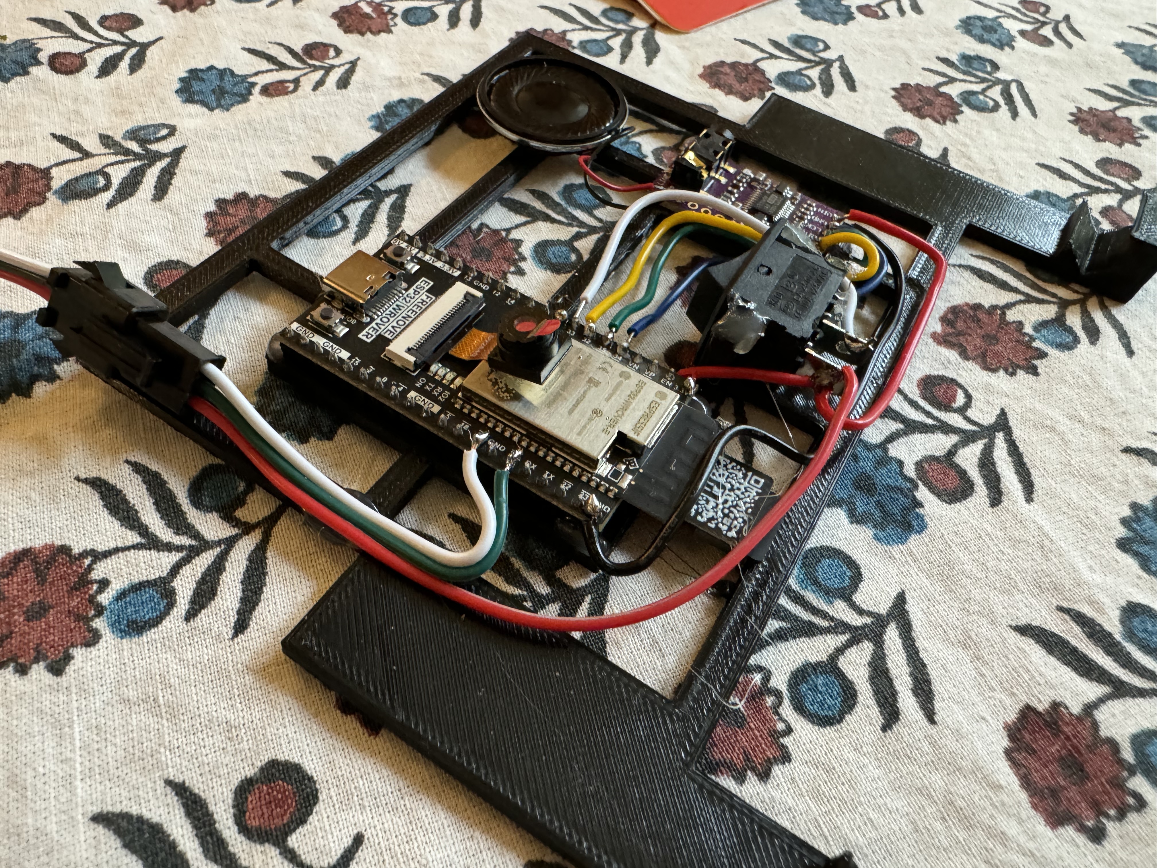
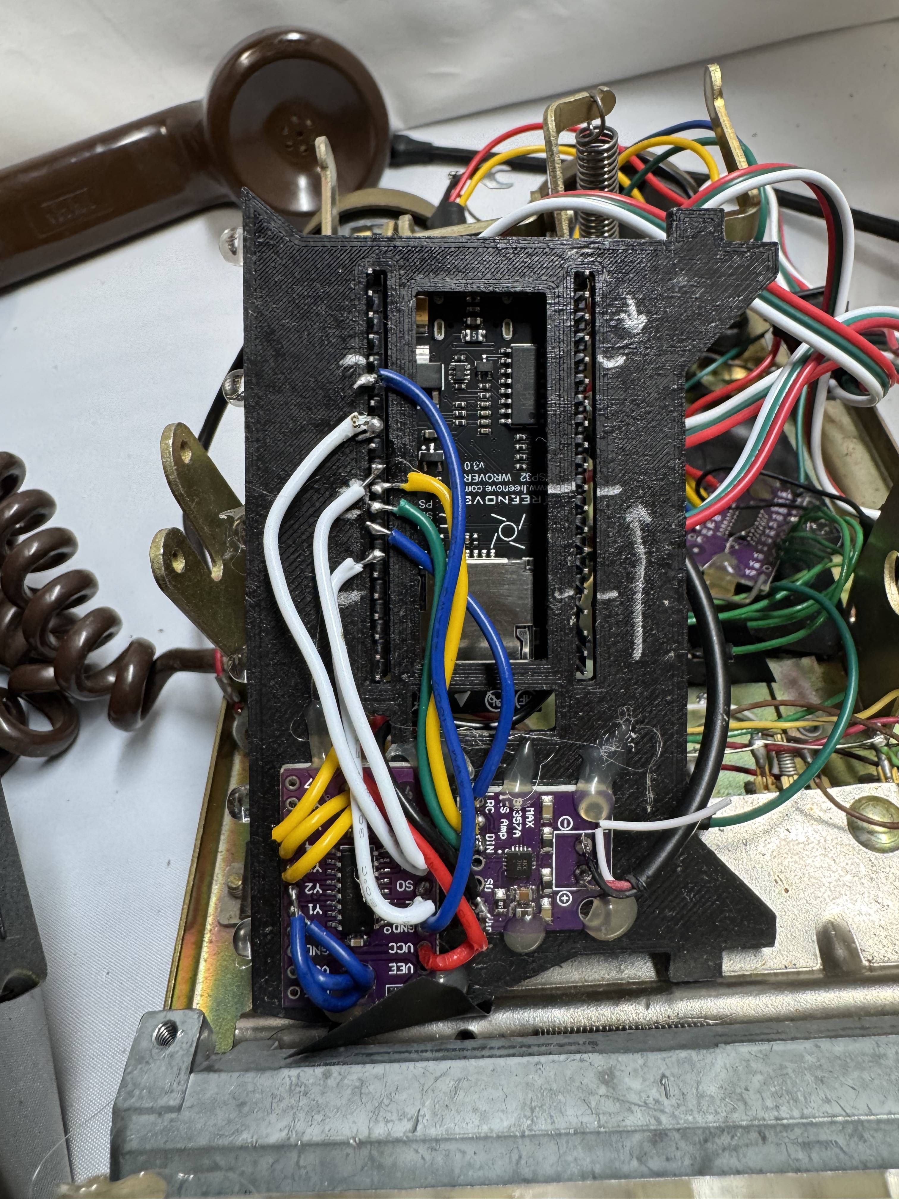
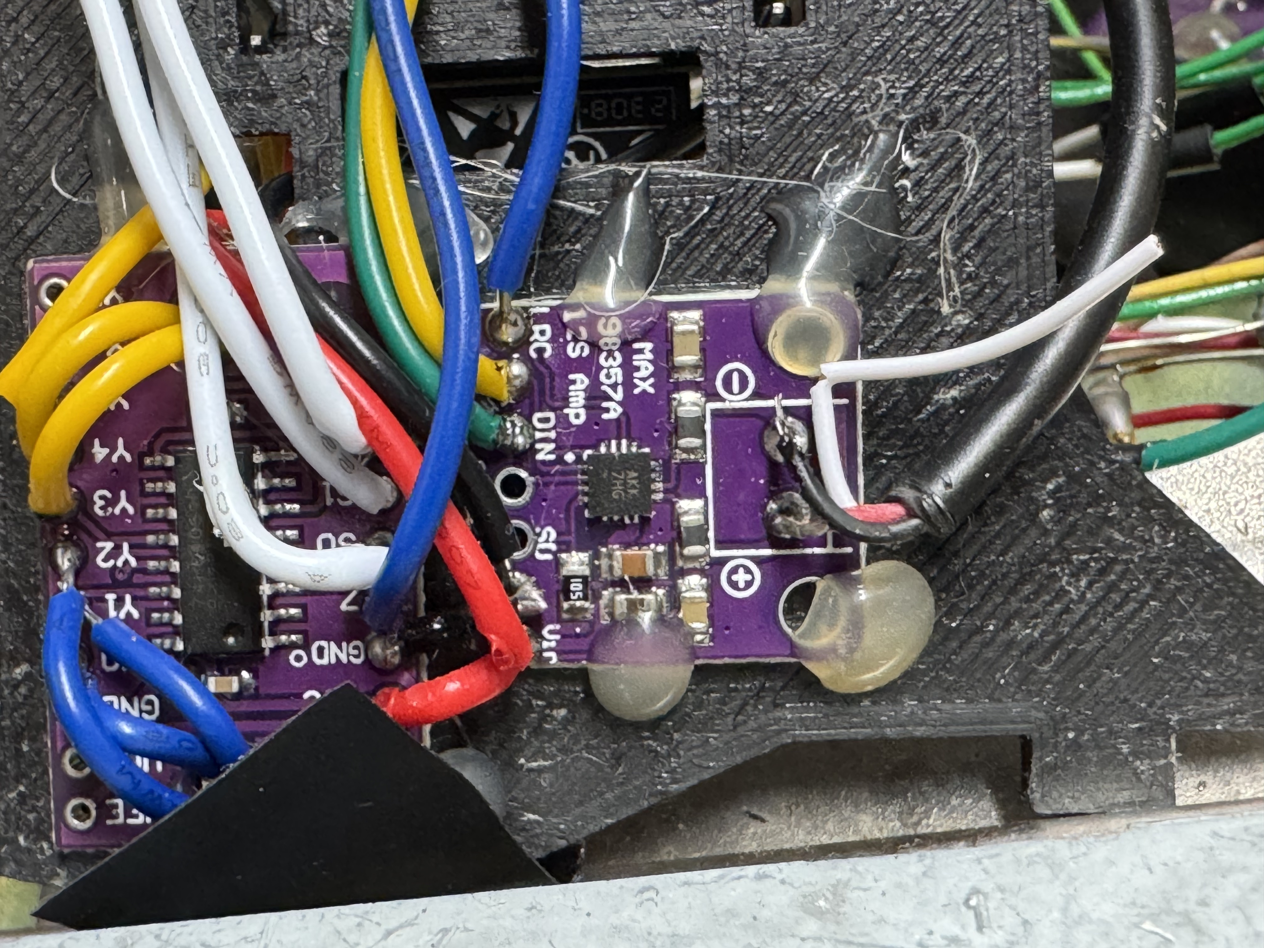
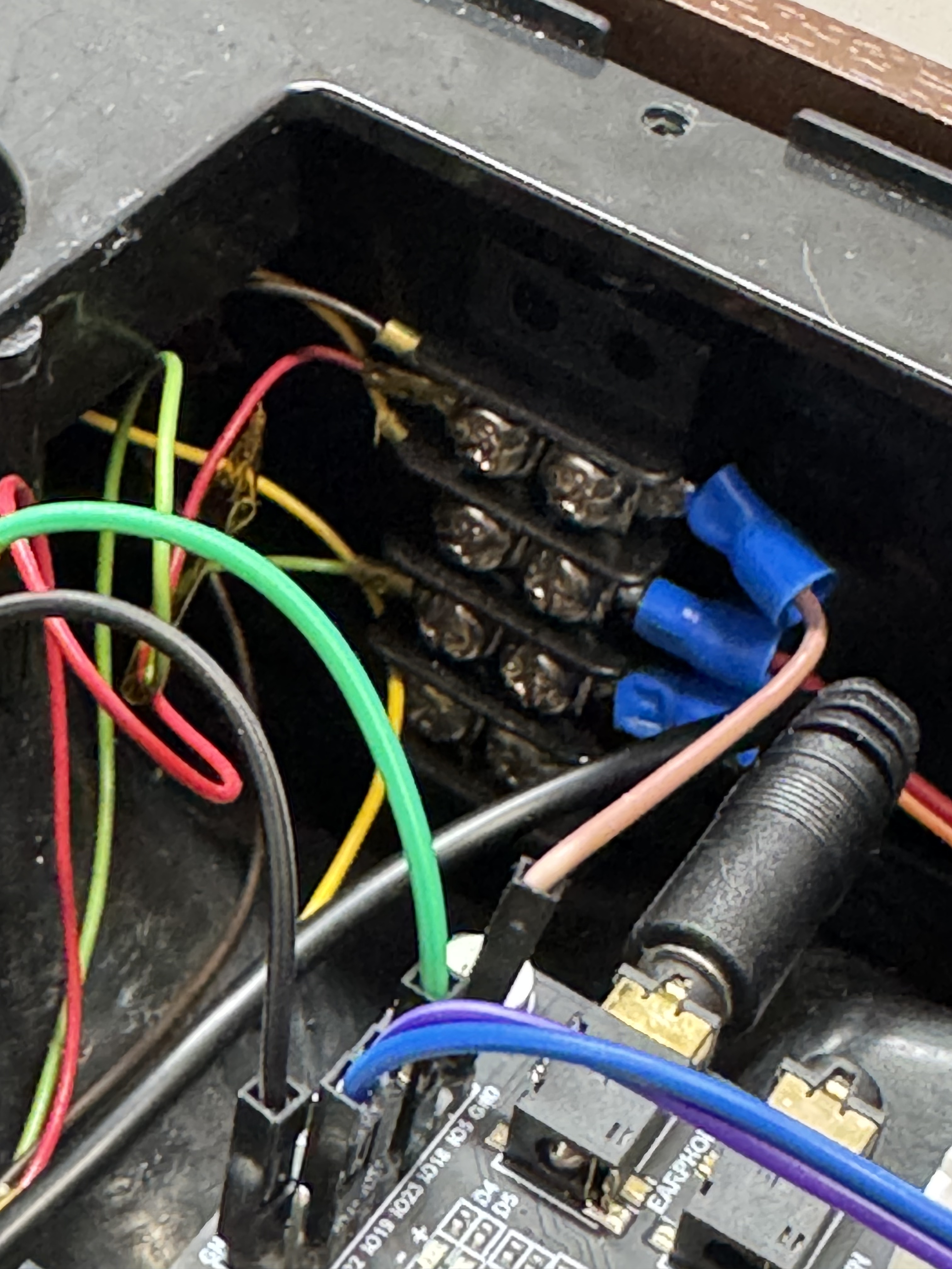
I tried to do clean wiring on this one. With the ESP32 I used for this version, Freenove CAM Board, it came with headers. I used those below through this mounting plate that swiveled to connect to a MUX and audio amp, a MAX98357.
This version of the phone, was an actual phone… That cost $59 on eBay (ones with all the lines were extra), then same $17 ESP32. I installed a few LEDs, MUXes, and an audio amp. This version probably cost closer to $75, and I used this as my test bench for… Almost a year as I on and off worked on this.


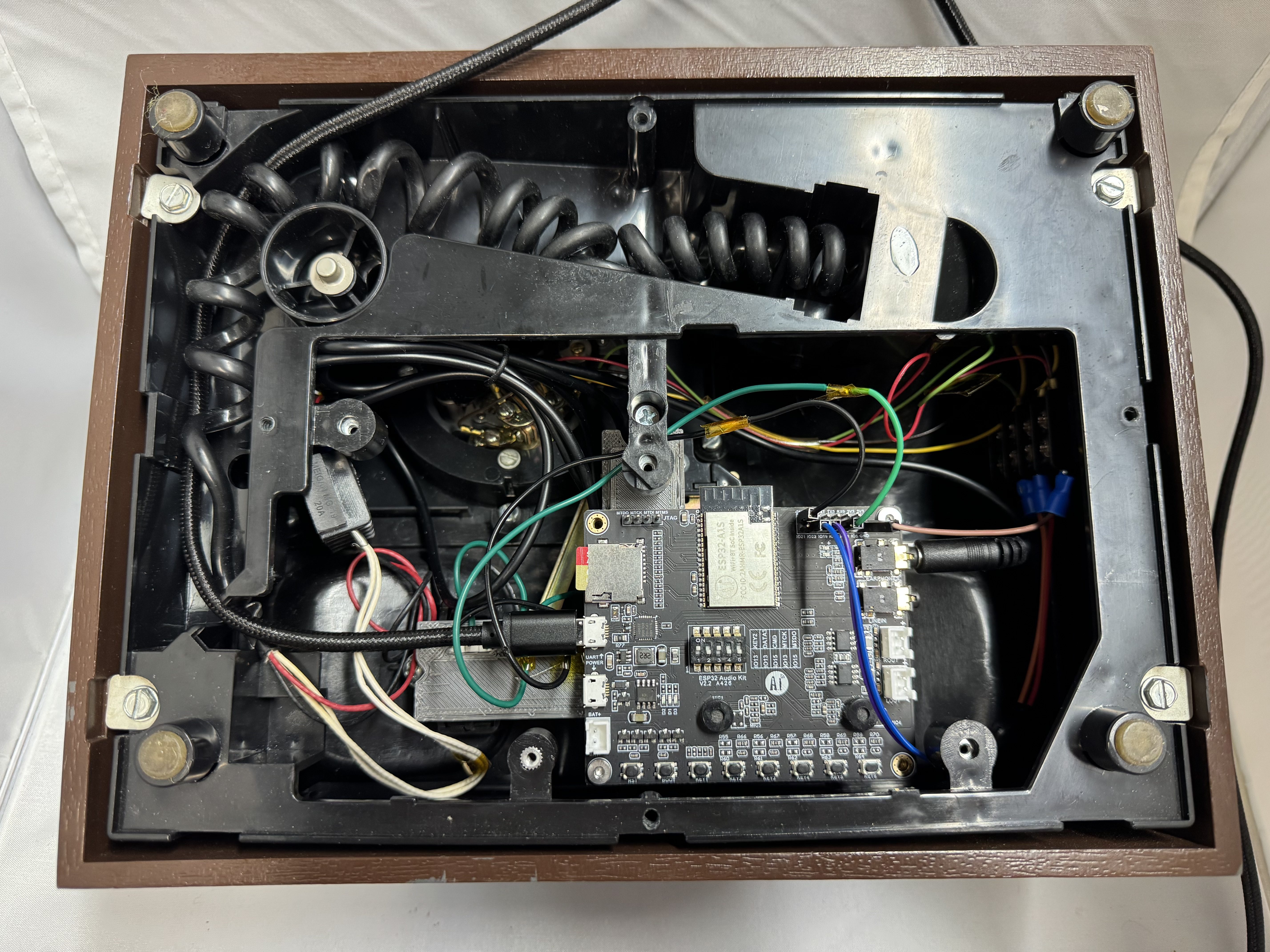
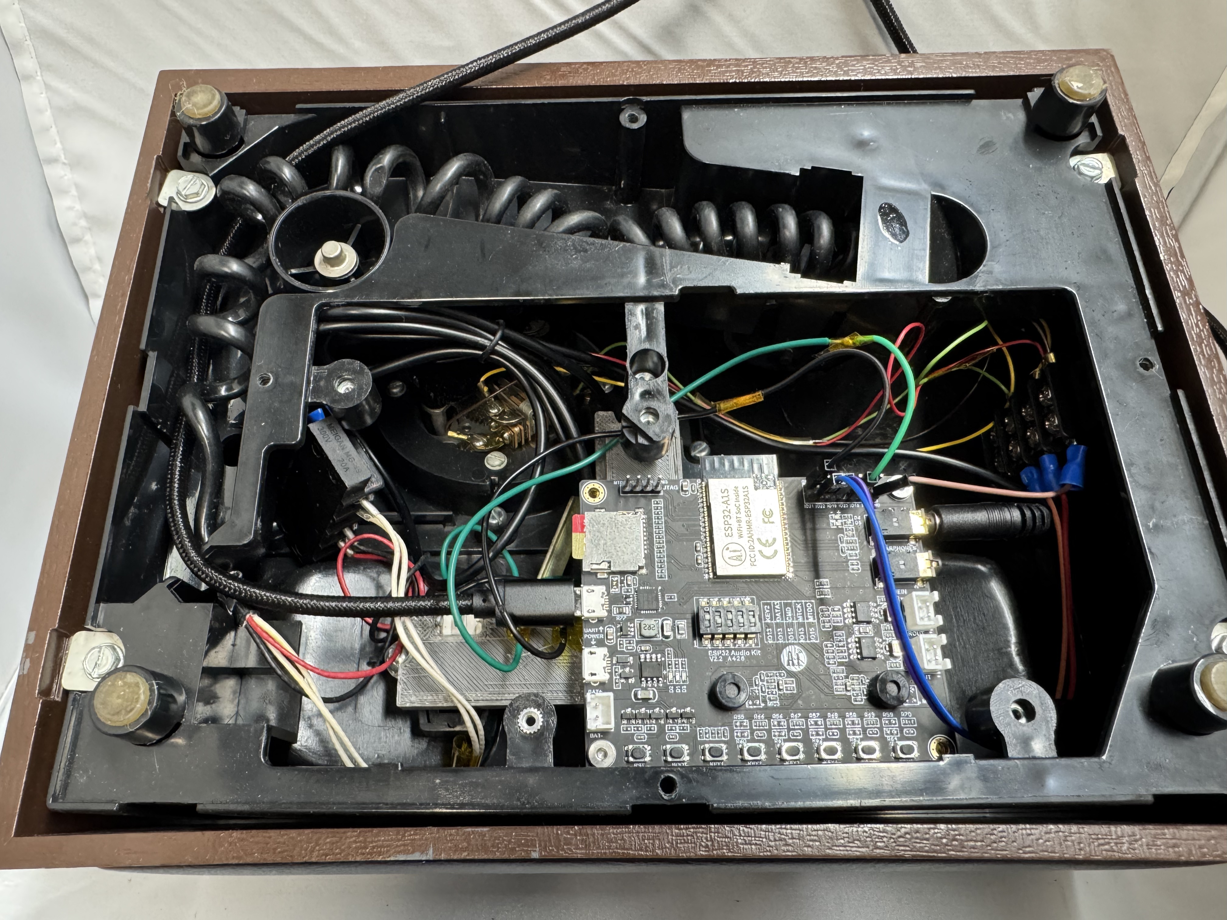
Fancy Phone V2
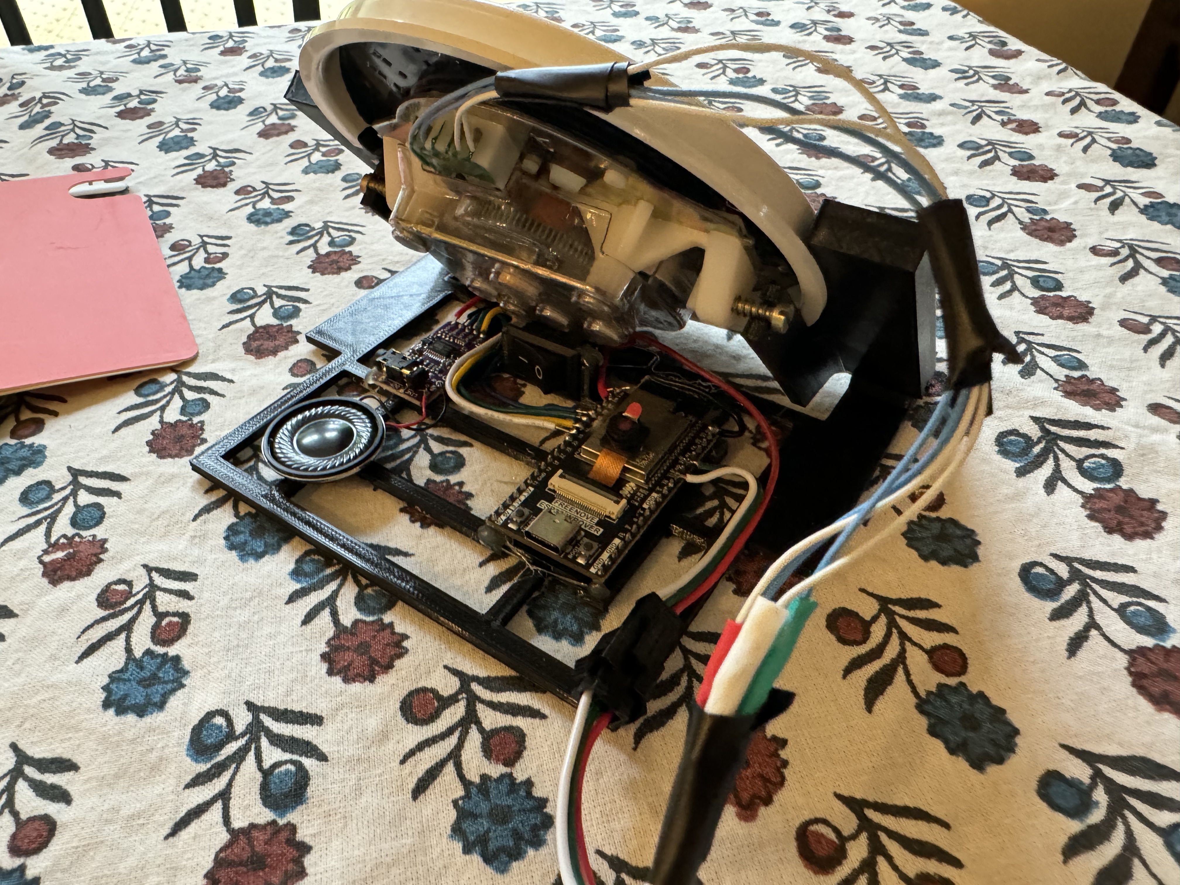
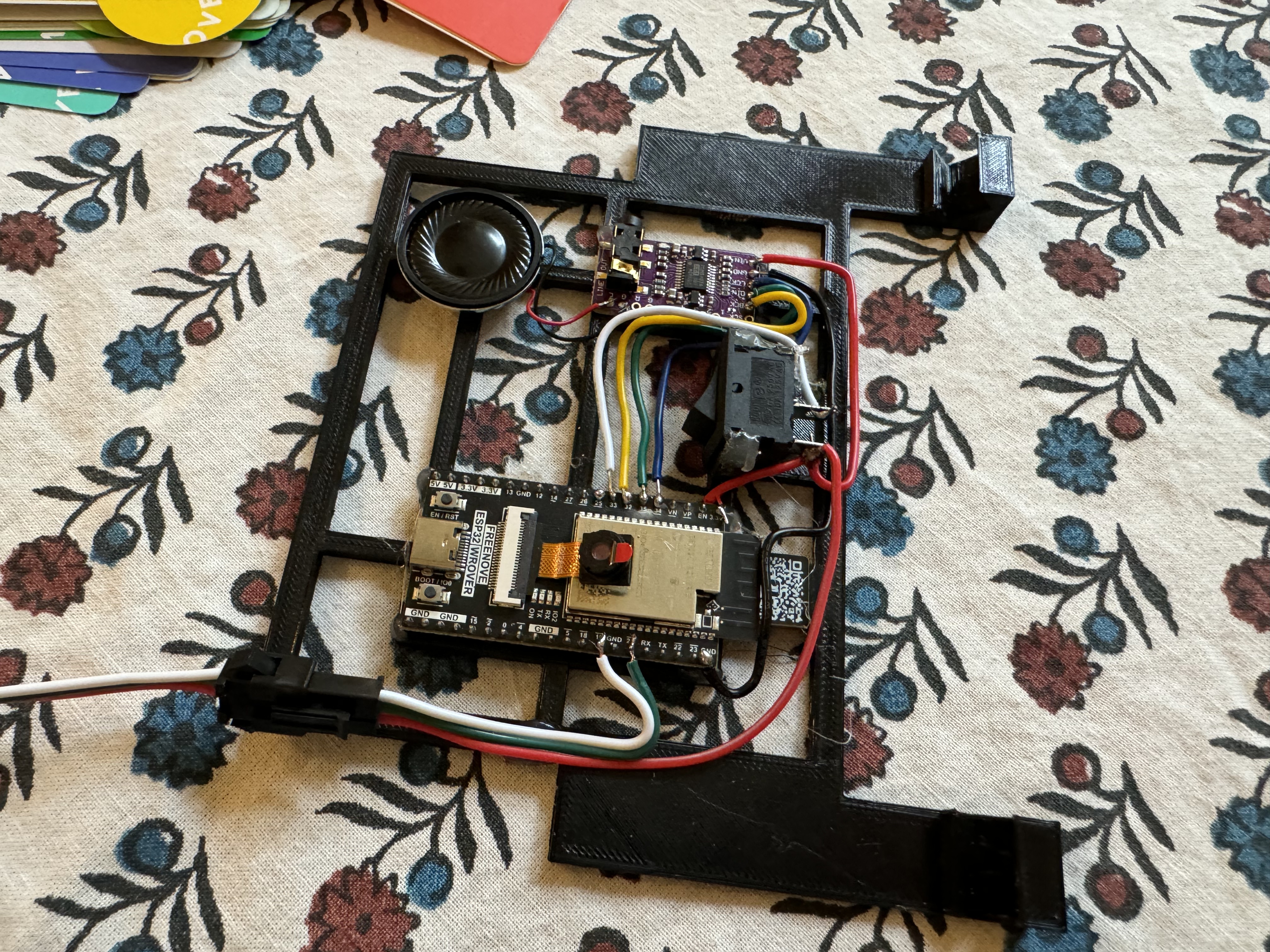
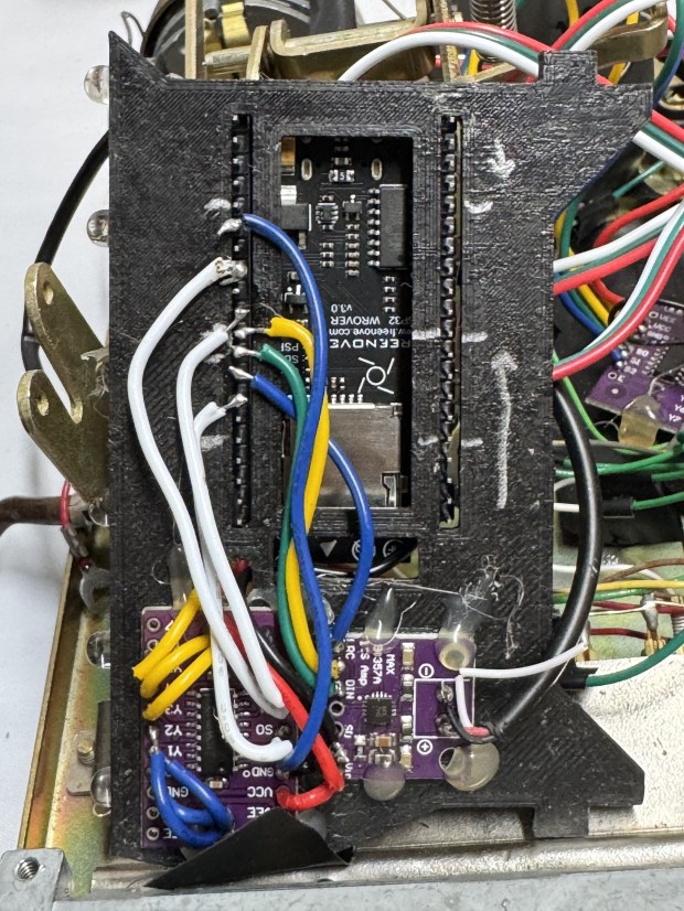
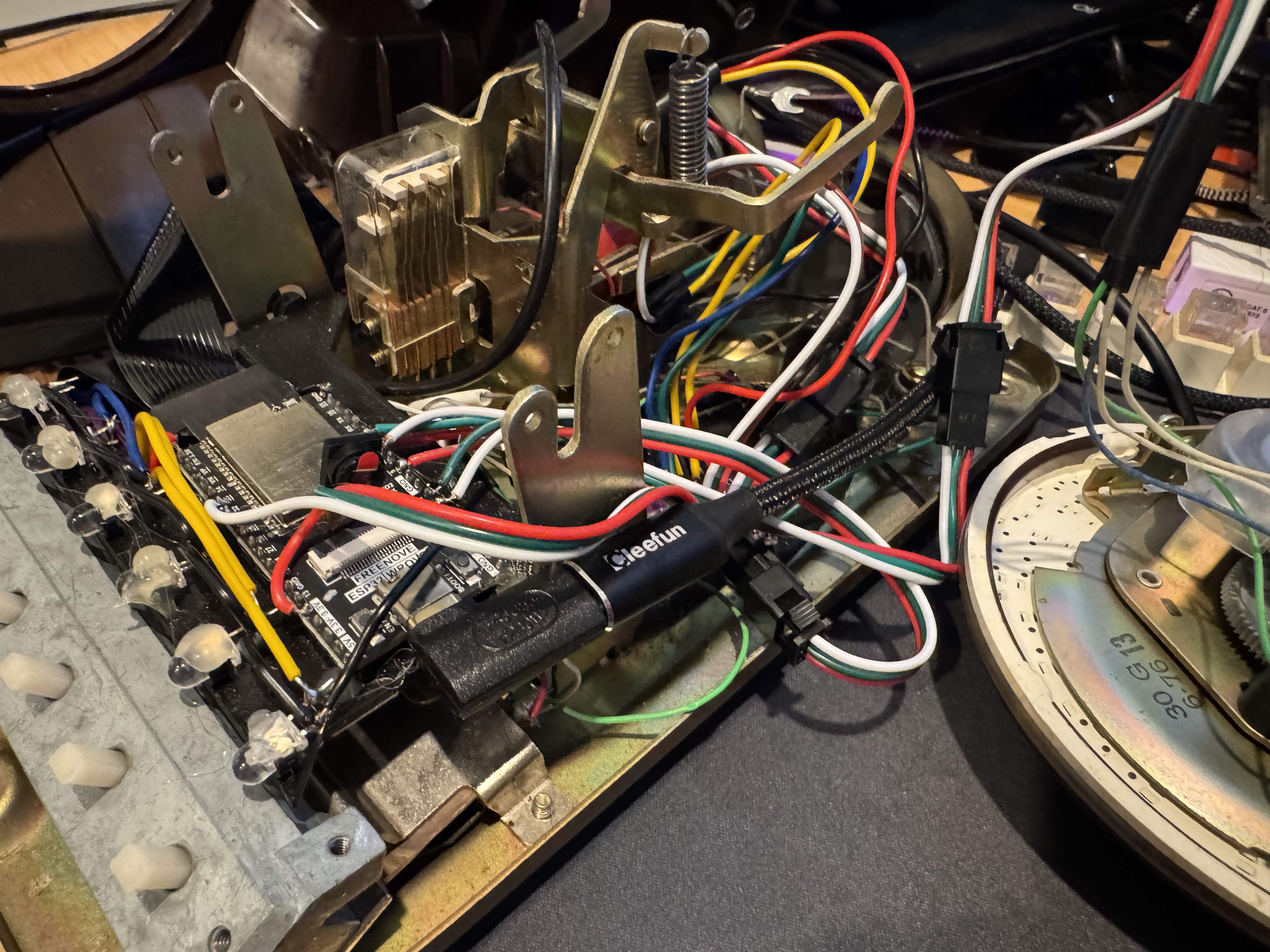
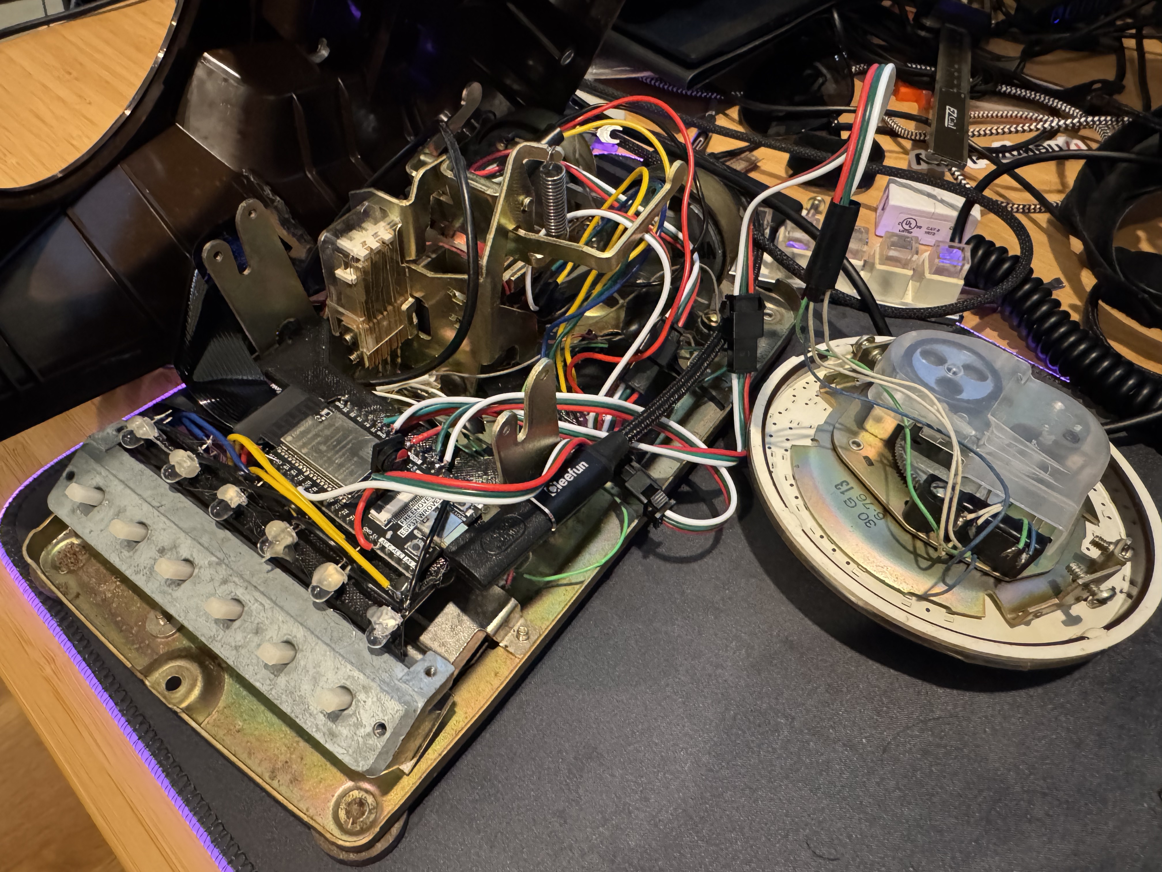
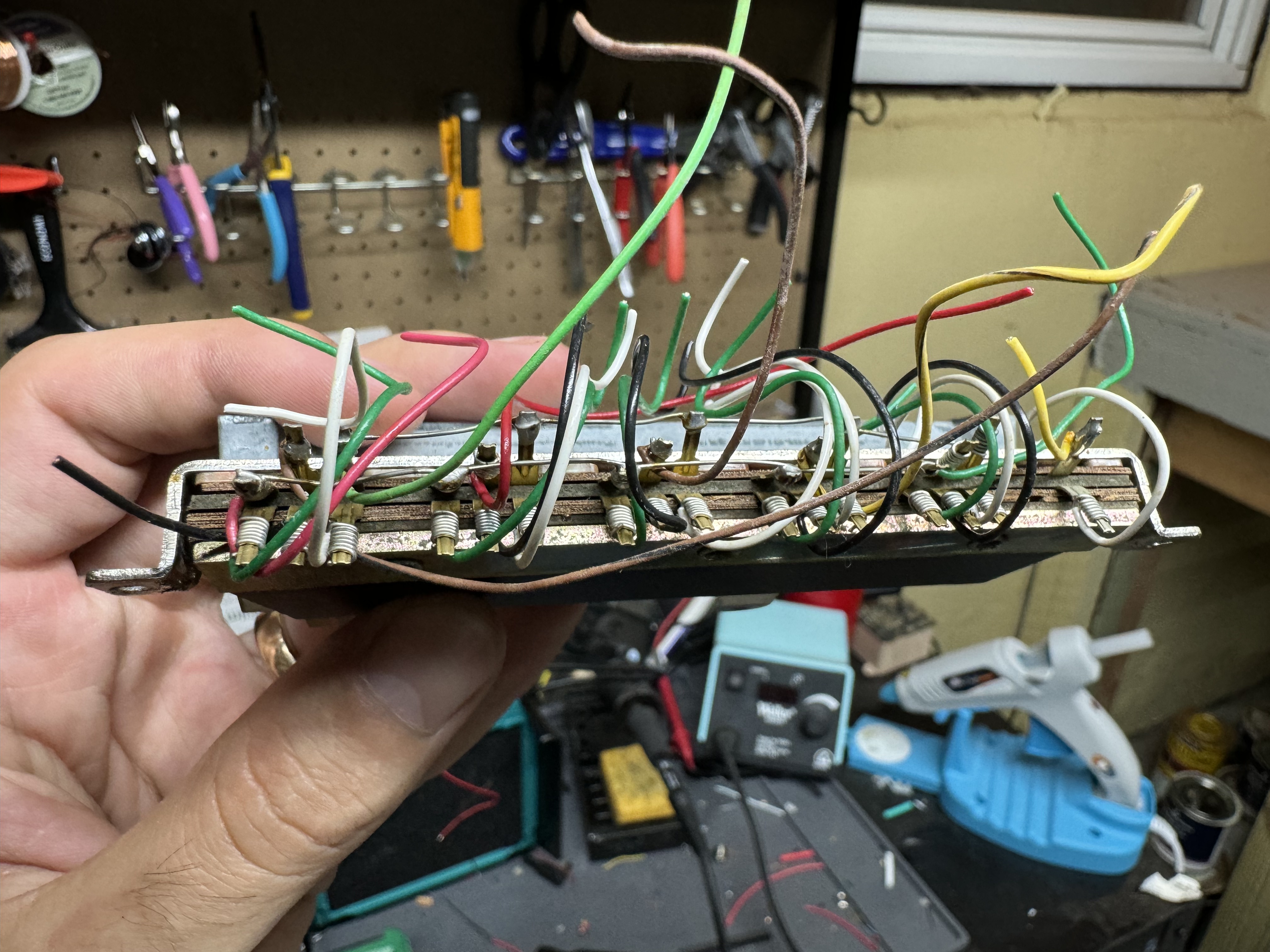
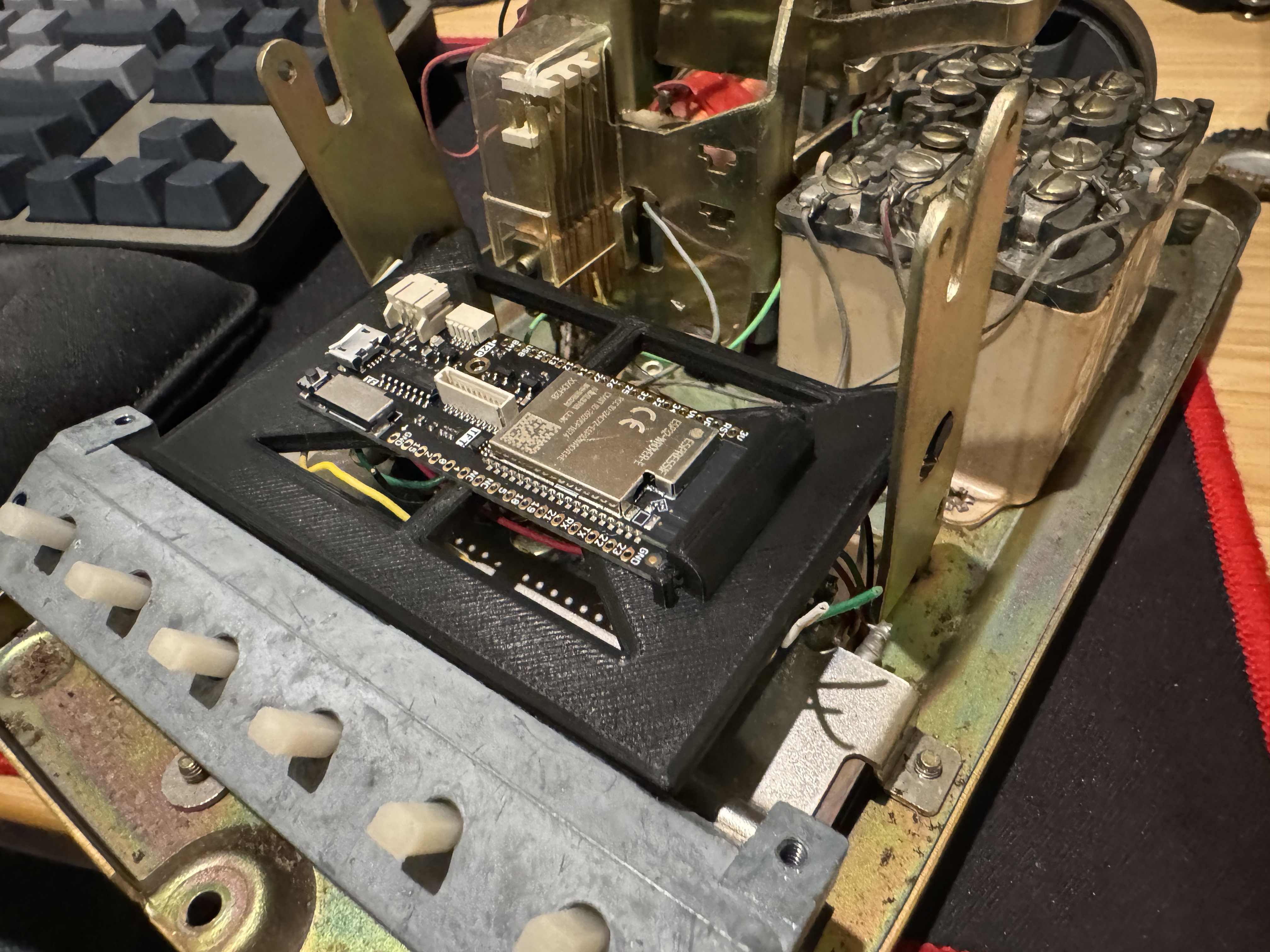
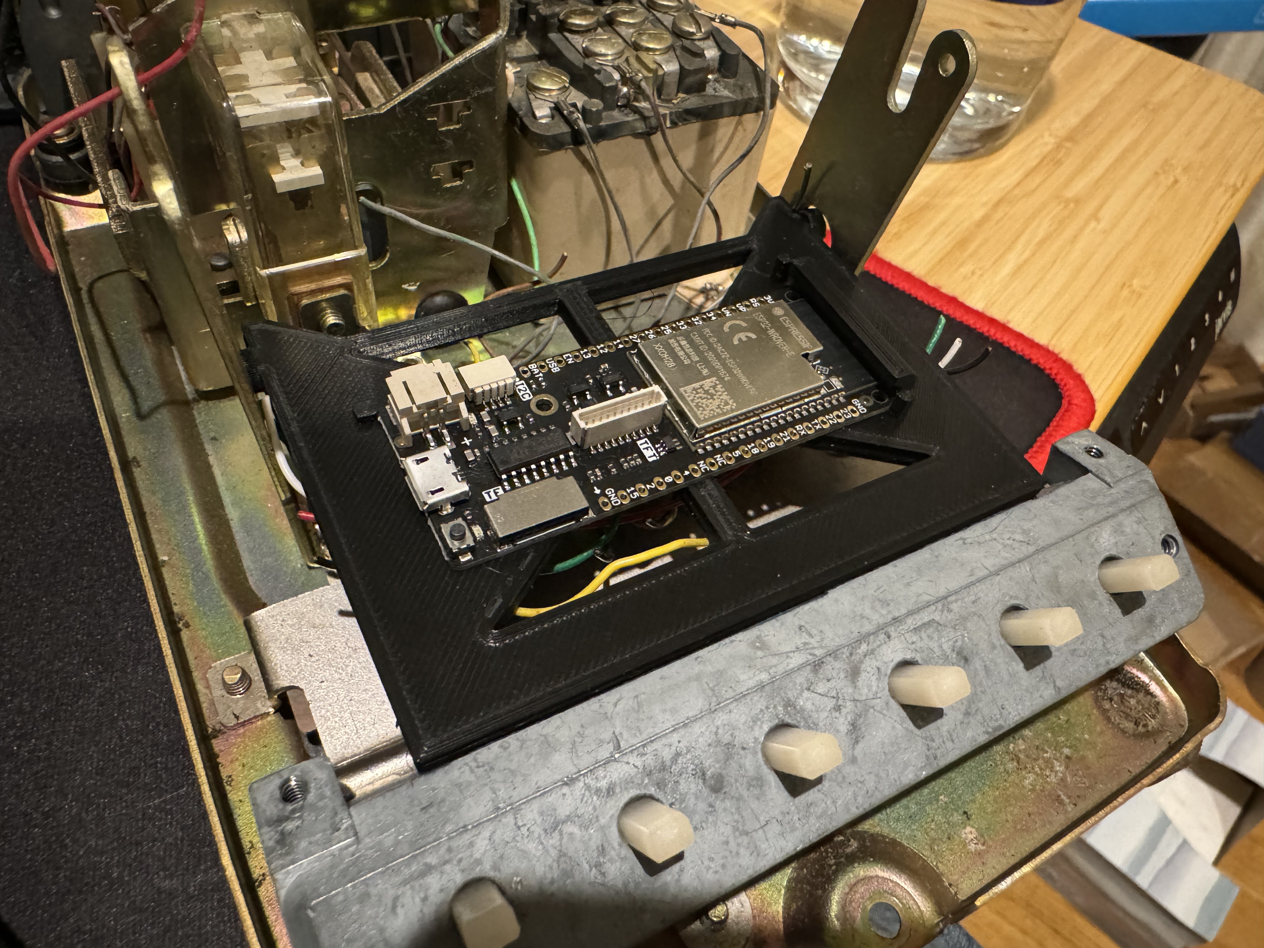
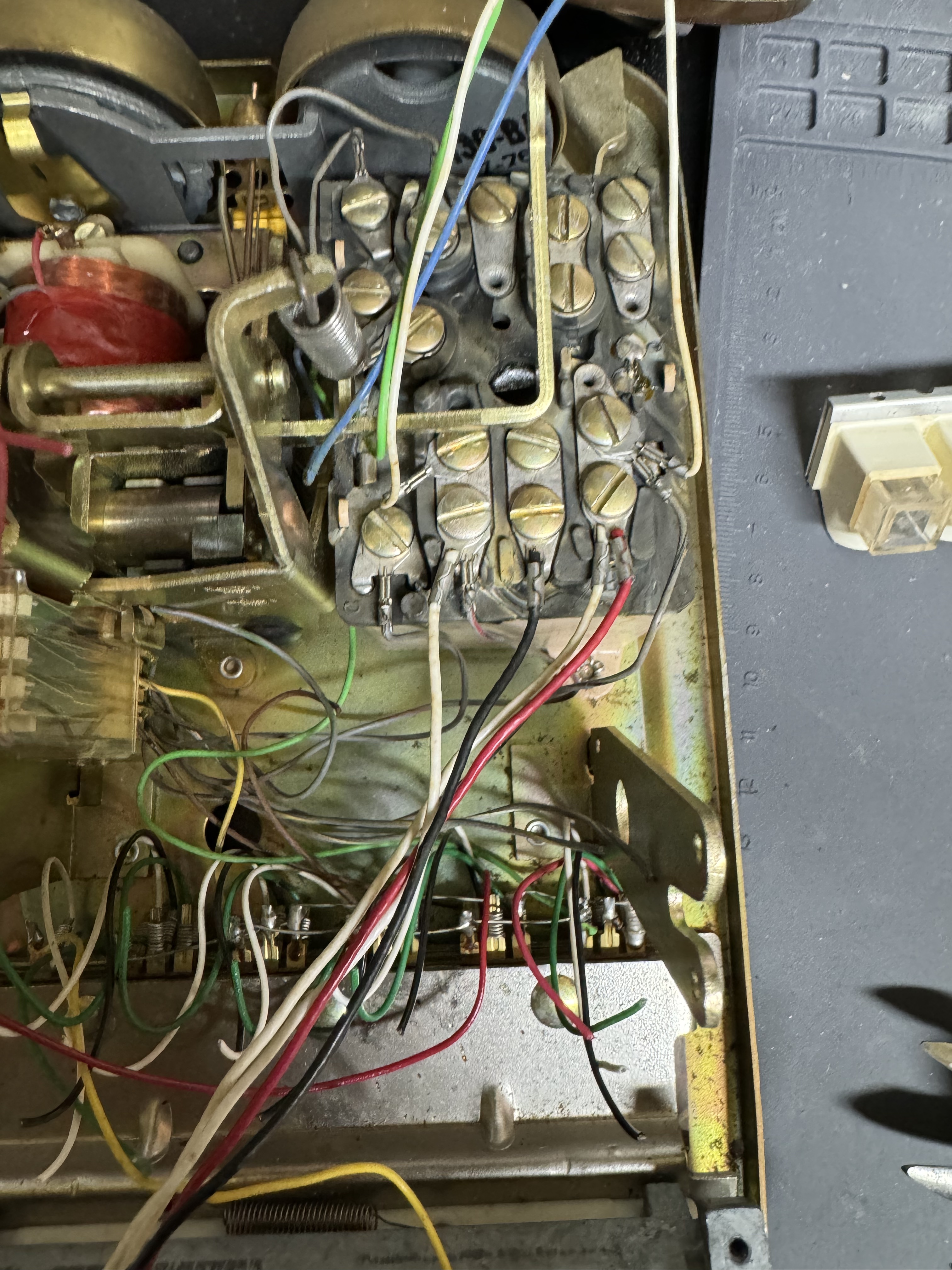
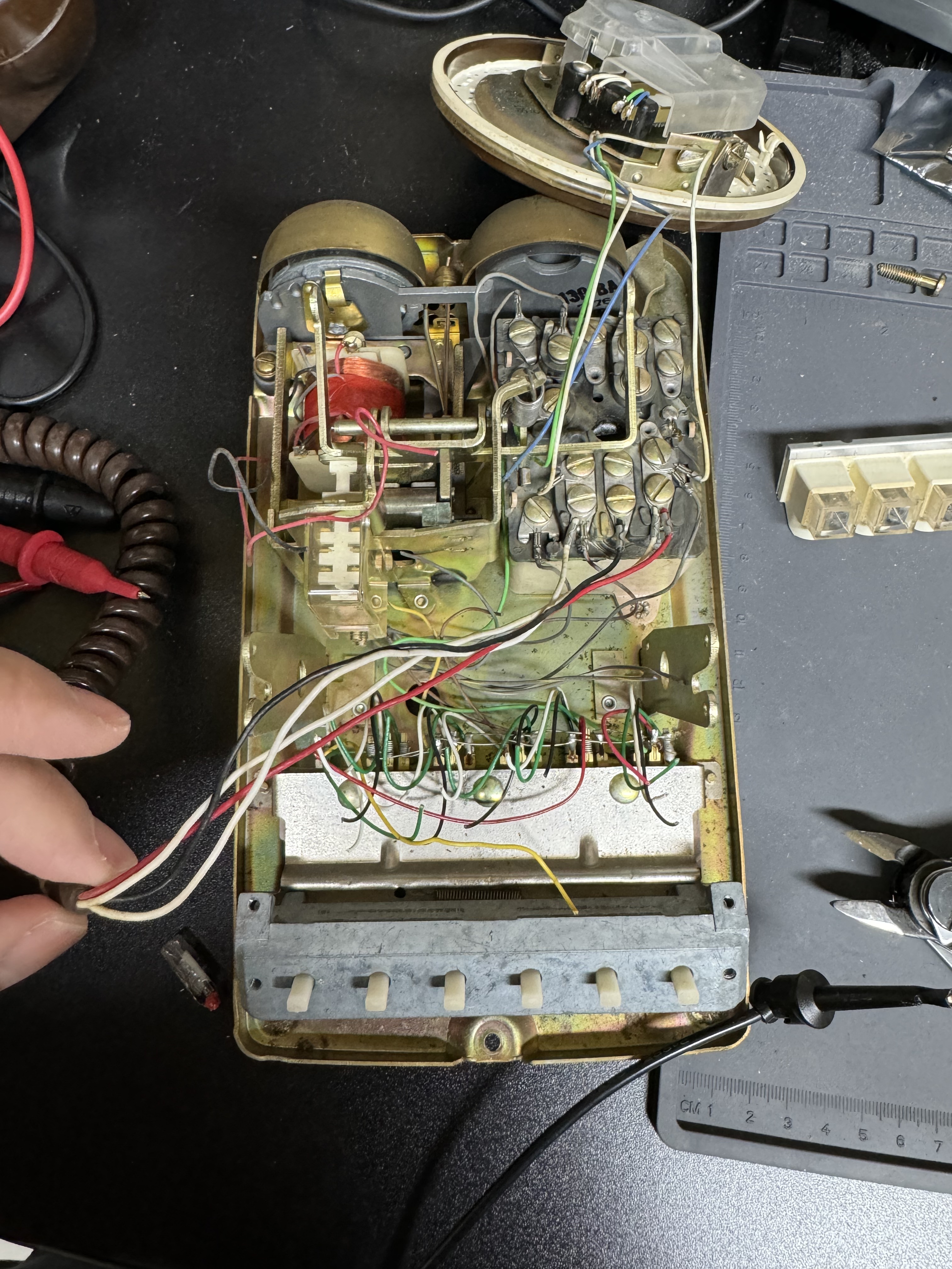
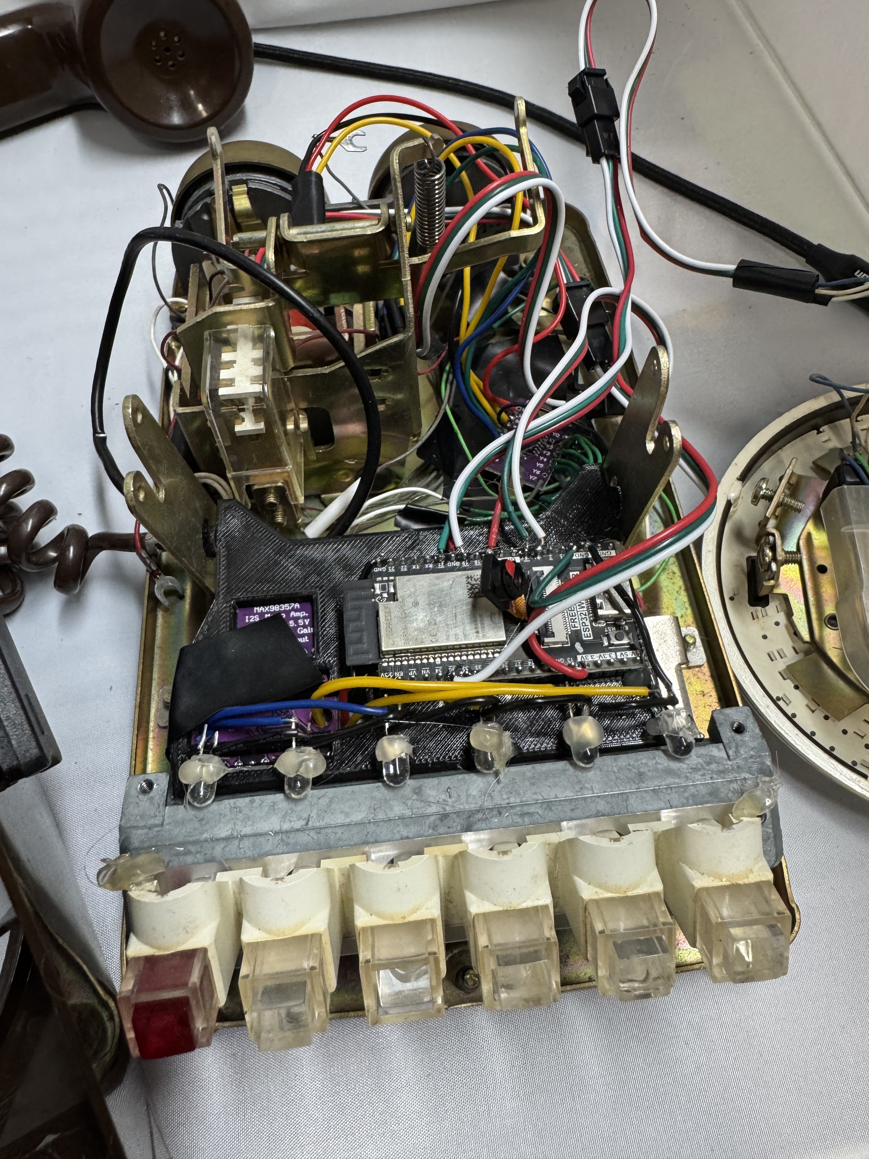
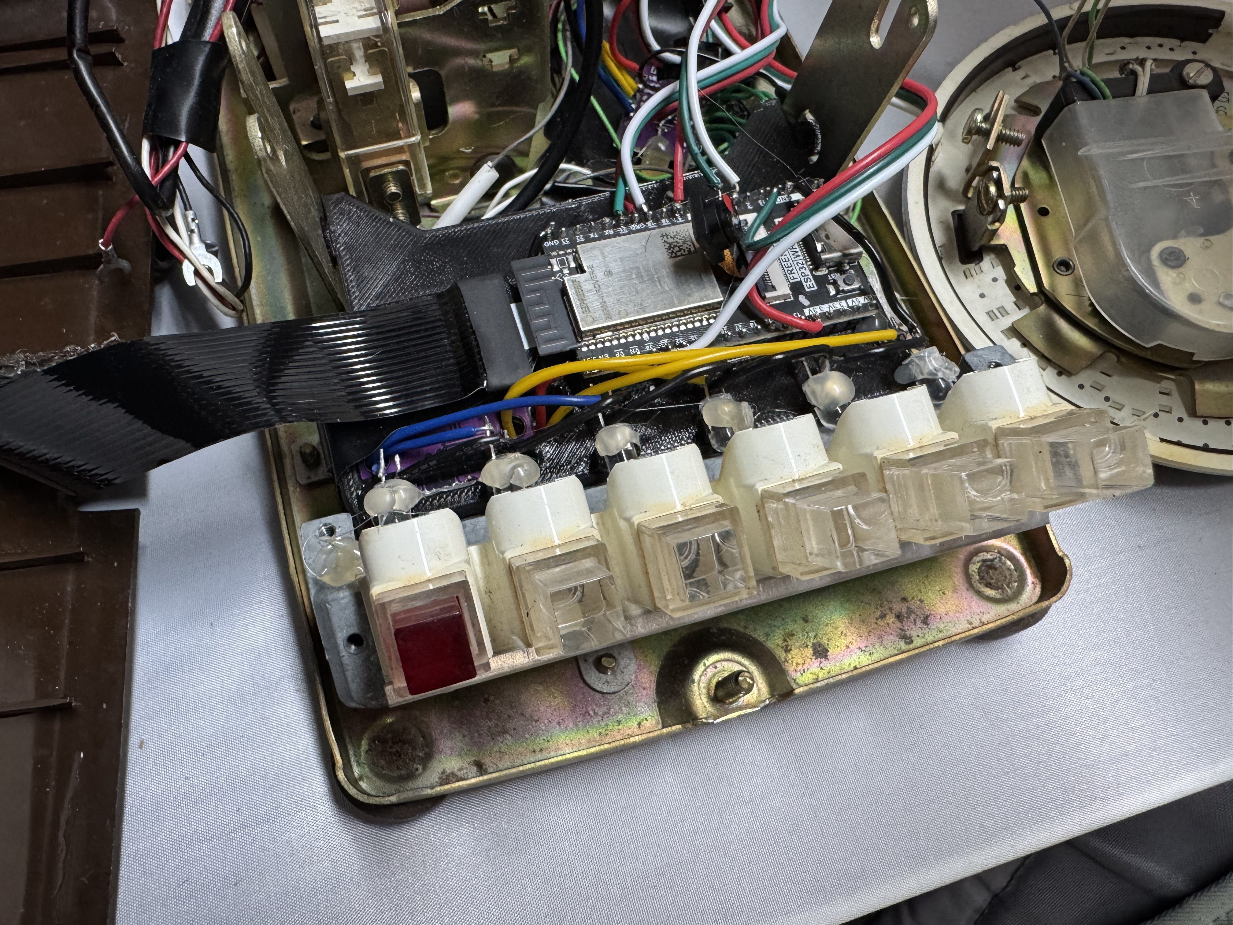
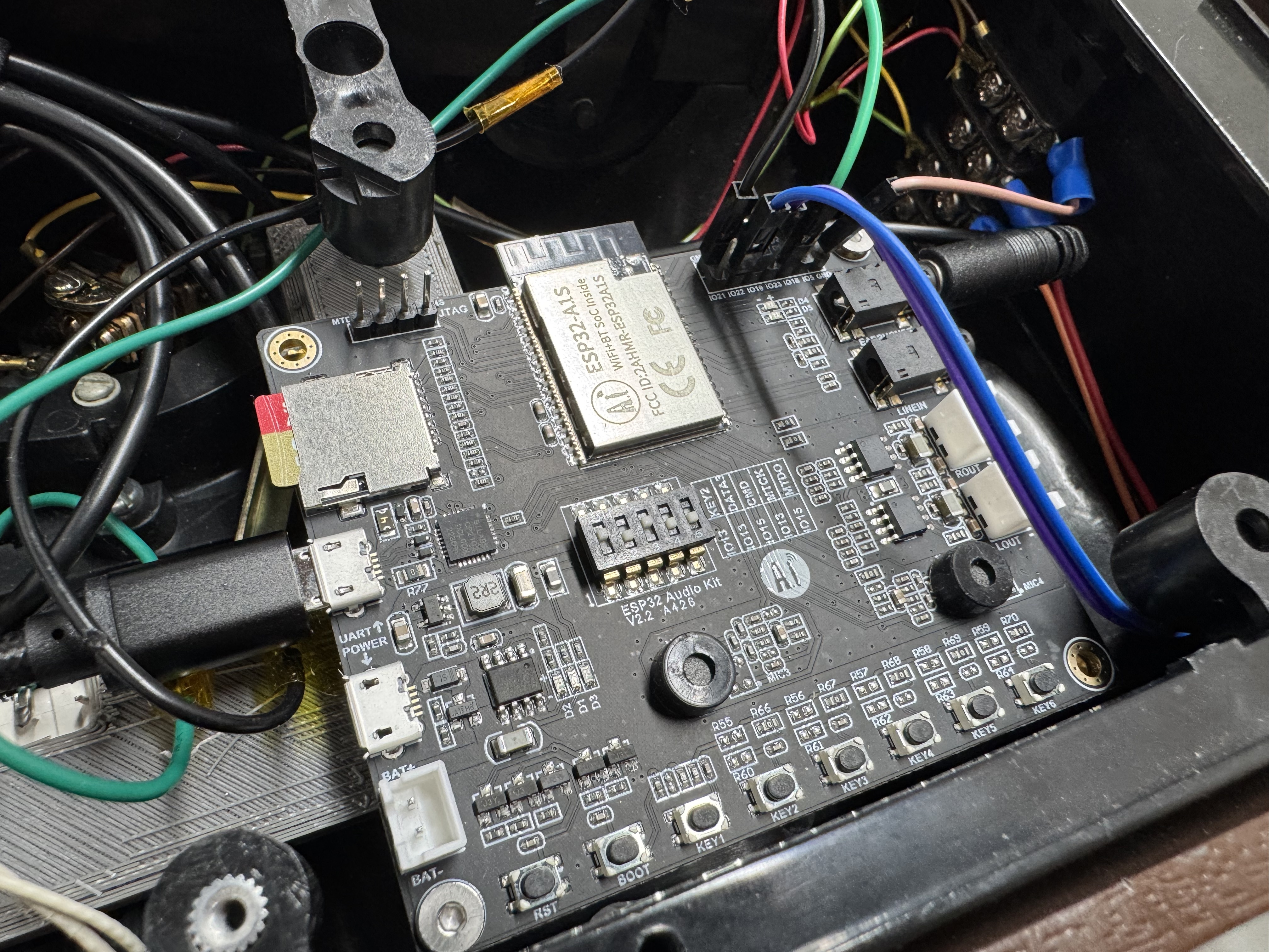
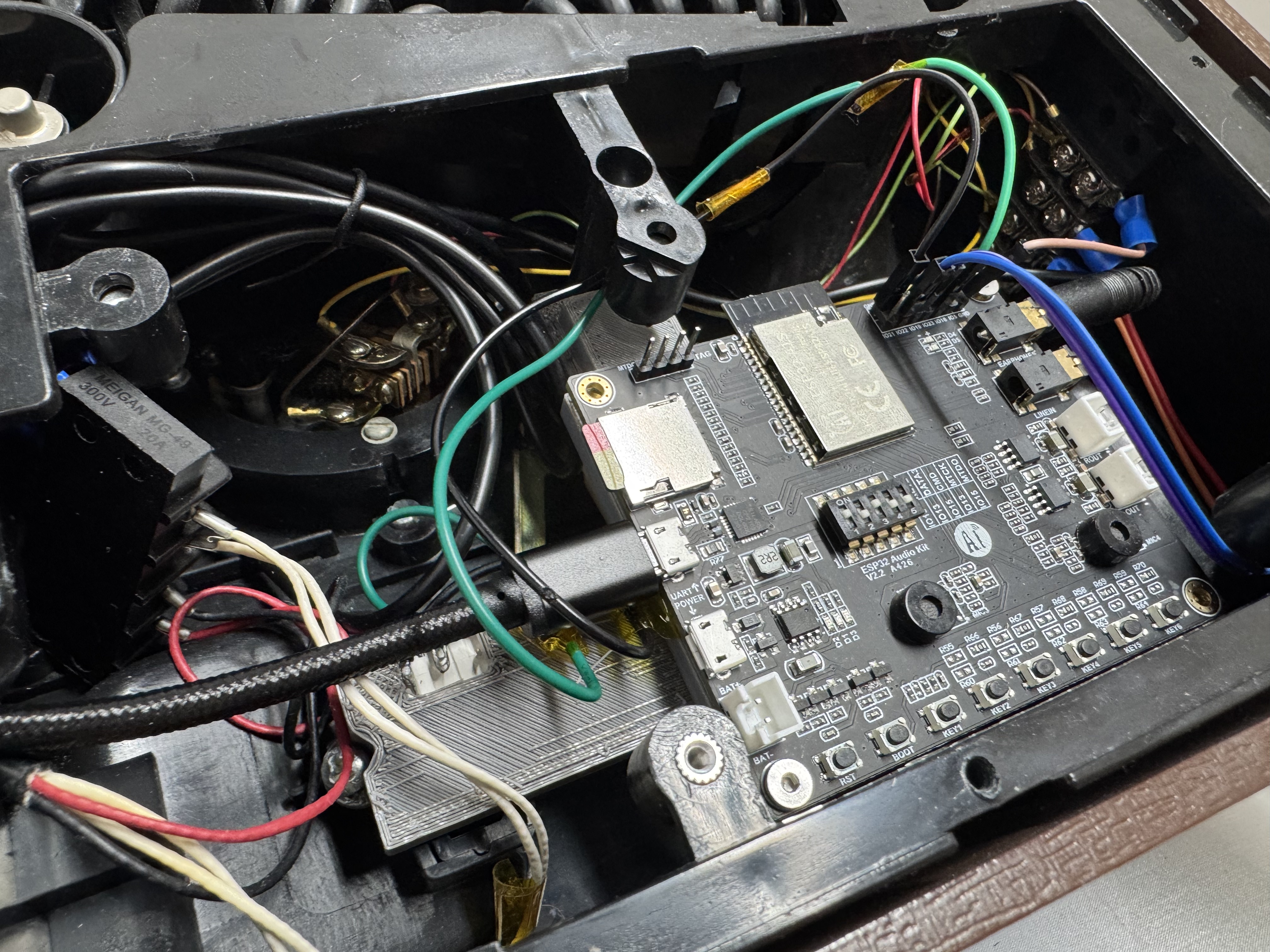
After how complex (see wiring photos, scream in horror) V1 became, I wanted to go back to the start and make a simpler one with the core phone functions. I also found this board that included an SD card reader, and audio amp all for $20, meaning I could use a phone, and this card for everything.
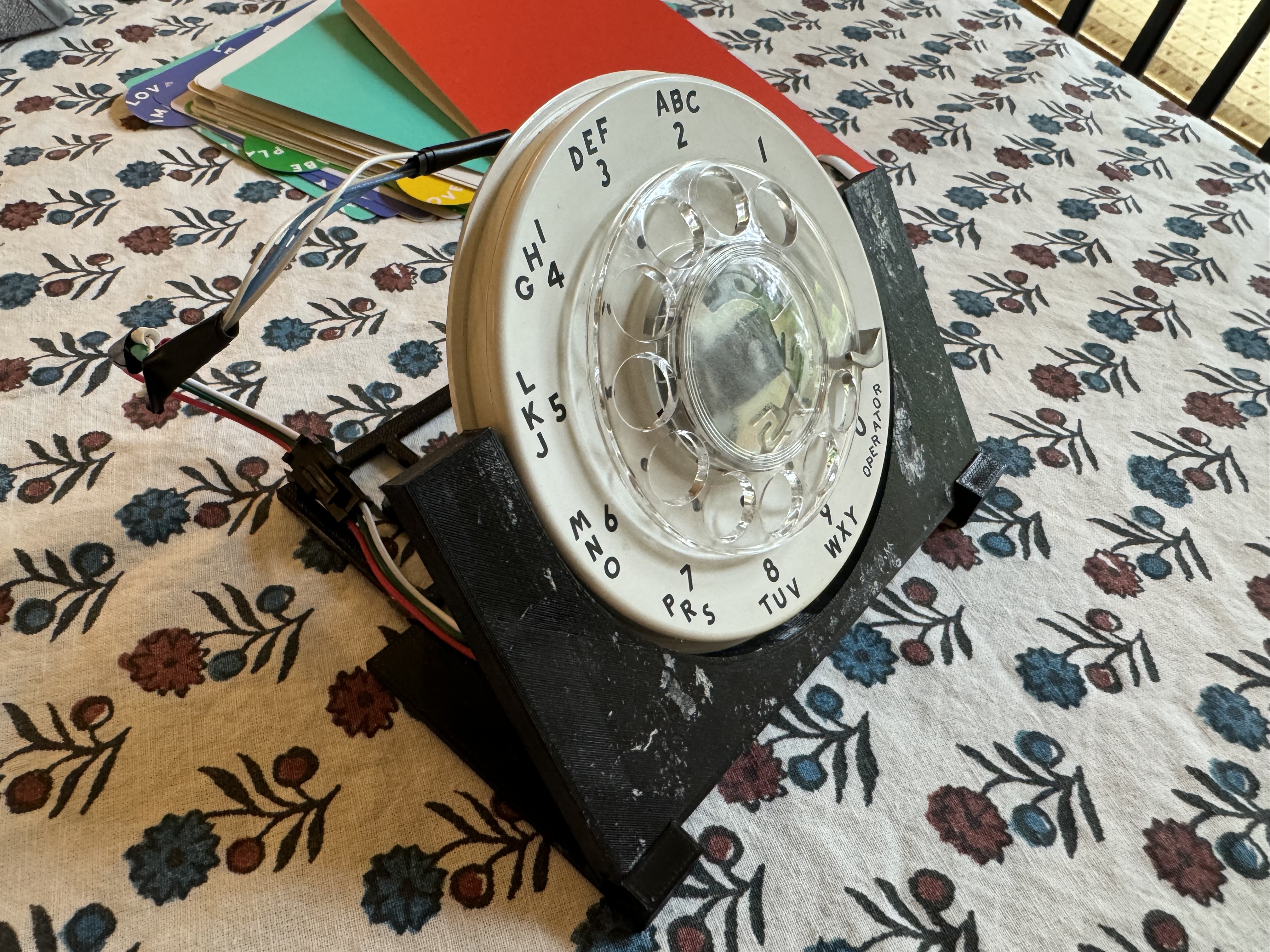
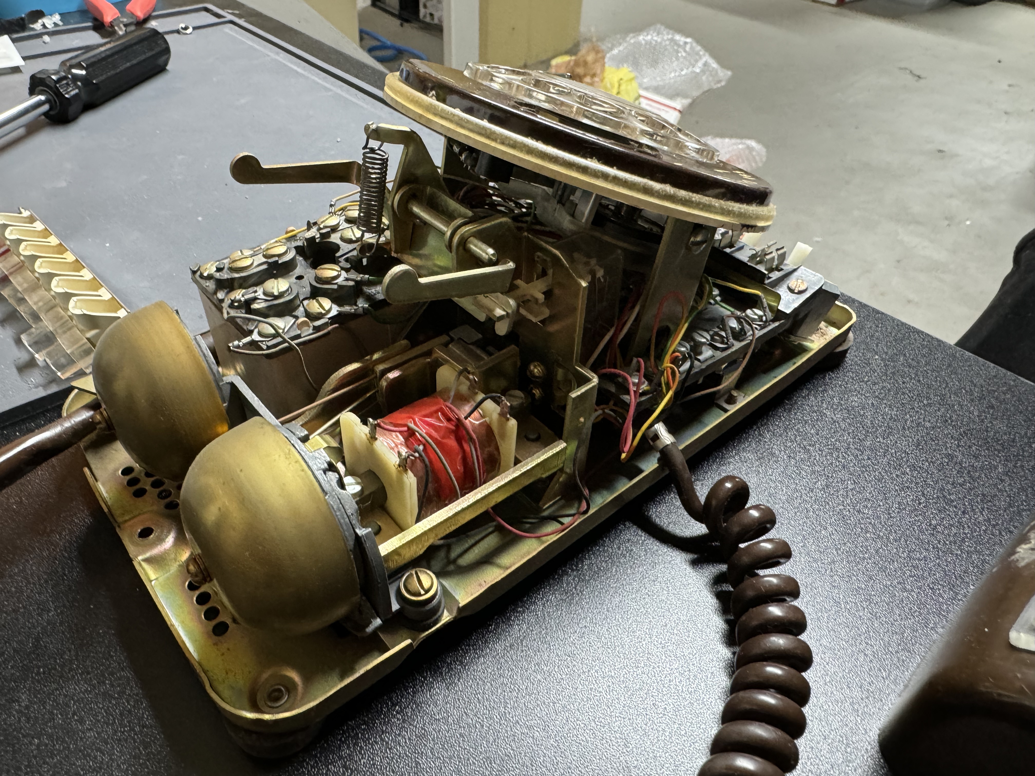
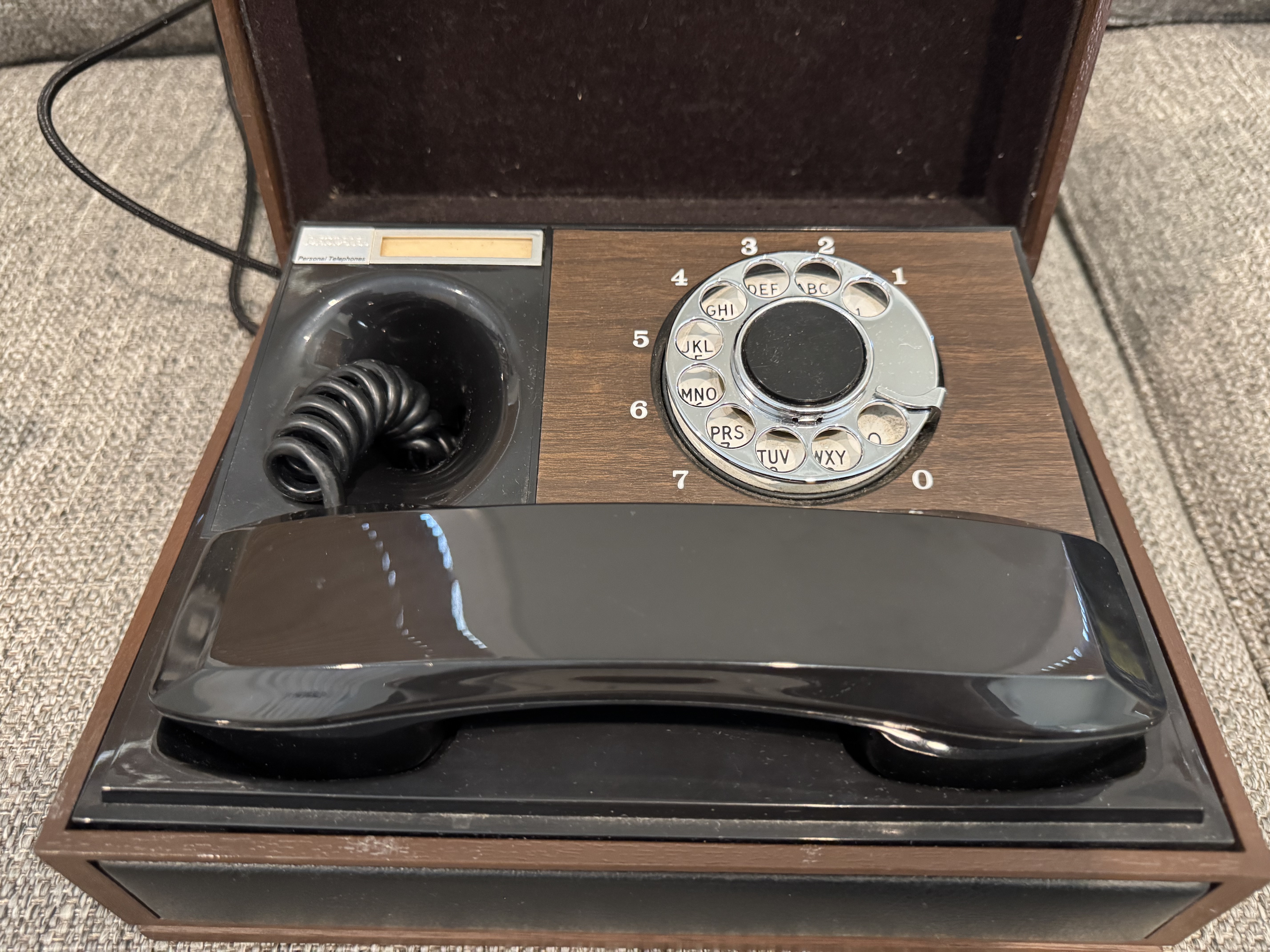
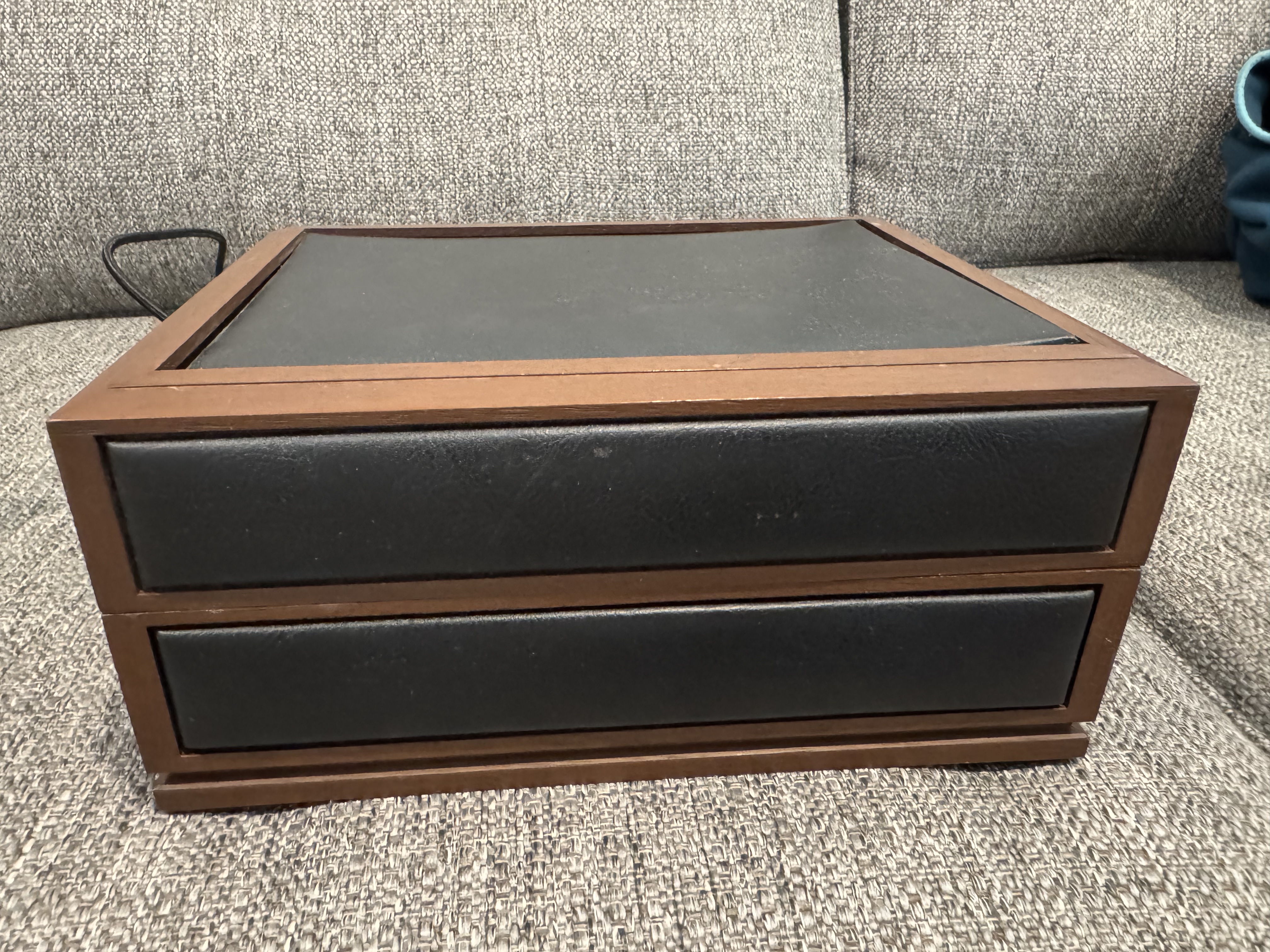
At this point I am doing my normal eBay scouring, and come across this nice executive desk phone. It’s simple, and the seller accepted my low offer! (I think eBay sellers just want to get rid of these phones) I wired everything up and I had a difficult time recreating V1. The main reason is what several reviews on Amazon said about this board (EC Buying ESP32-Audio-Kit Audio Development Board, ESP32-A1S); it has basically no documentation. Luckily, one person mentioned a repo that had a ton of information on the pinout, and that worked for me.
I probably would use this board again, because now I know how to make it work; but it was not forgiving to get working. There appear to be a bunch of companies that have this same board with different names on Amazon. There are different revisions and you don’t really know which one with which pinout you will get till you get it. The company has a github repo that has SOME information, but not all.
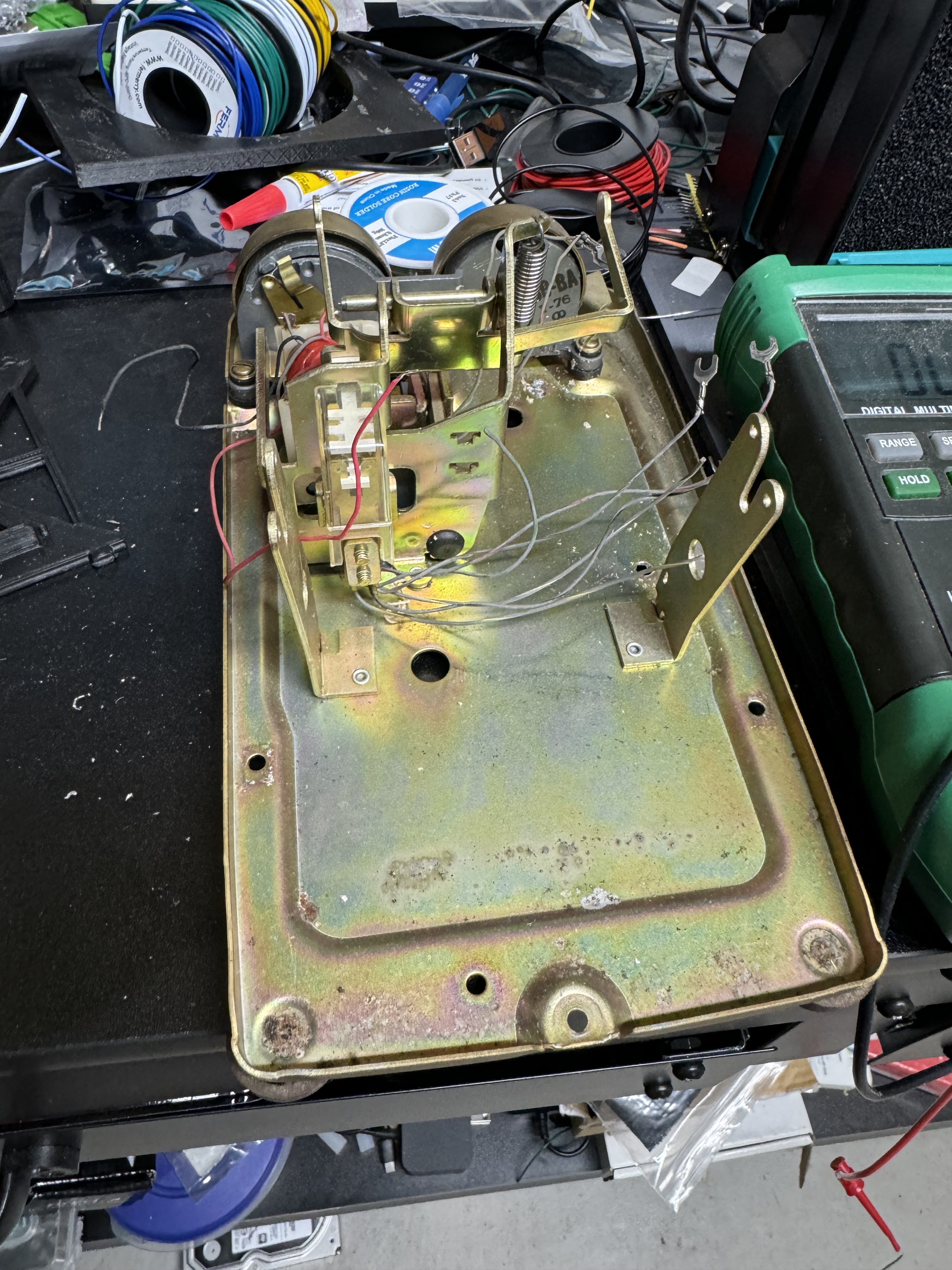
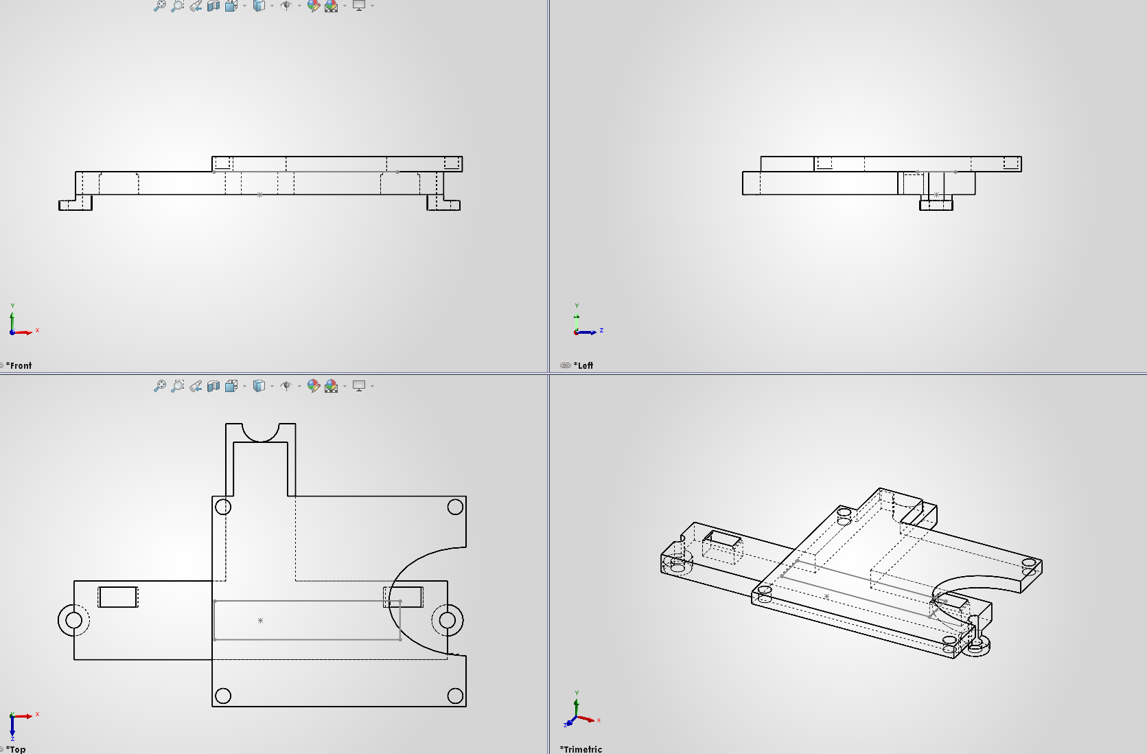
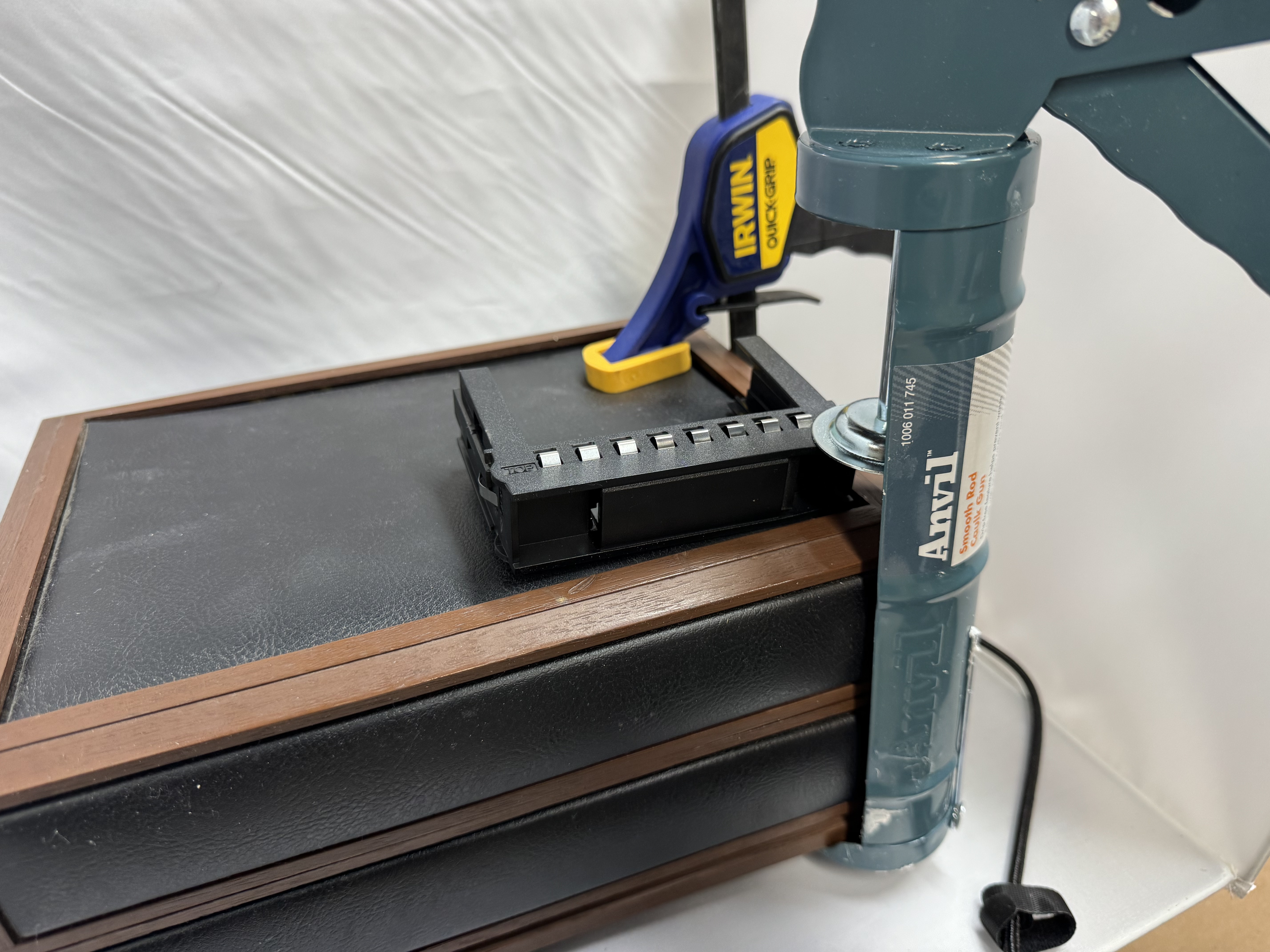
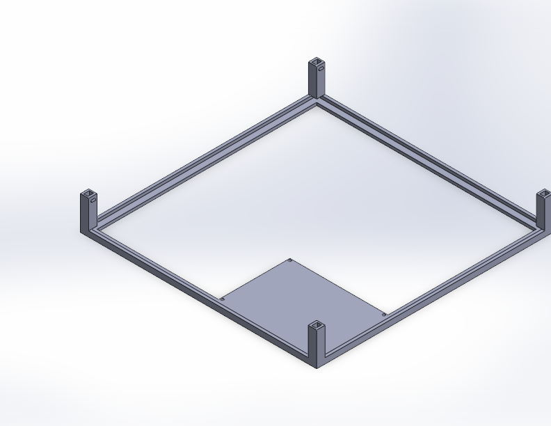
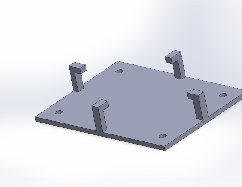
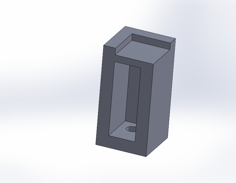
For this phones hook signal, I had to remove the piece that would usually be triggered to fit in the ESP32. I modeled and then 3D printed a bracket that holds the ESP32 in the bottom, and at the same time it has spots for two switches that get contact when the handset is put down.
This version of the phone I got (all these prices are with shipping) for $35, its a nice solid unit. The new ESP32 board was $22. Then I added 2 switches because I needed the hook signal, and some terminals. This version of the phone was closer to $60, and I spent about a month here and there on it.

File Structure
The SD Card has 2 main folders, content and web. Within content, there are some of the stock tones like a dial tone, then there are folders for each year. Within each year: photos, txt files, and mp3 files can live. The system will select at random an MP3 file if there is more than one. The files are supposed to be named starting at 1.mp3 and increment. The idea was you would have 1.mp3 and 1.txt, which would match up and have content matching with the audio. This wouldn’t be hard to make it not that way, but that’s how I was doing it. This is all documented more in the README, on the github page.
The web folder contains a Next.js React app that is built into a static site (a great Next.js feature!).
Web Interface
One feature that was an added on stretch goal was to have a companion website for the phone, allowing for photos and other media while stories were being told. The ESP32 can host a Wifi access point and web app, and I have been learning React, so this was a great place to keep learning! I used Next.js because I have used it before, and I know it can create a static HTML version of your site. I had to overcome some CORS and api issues, then it was smooth sailing. I used the next.config.mjs file to add redirects while doing development.
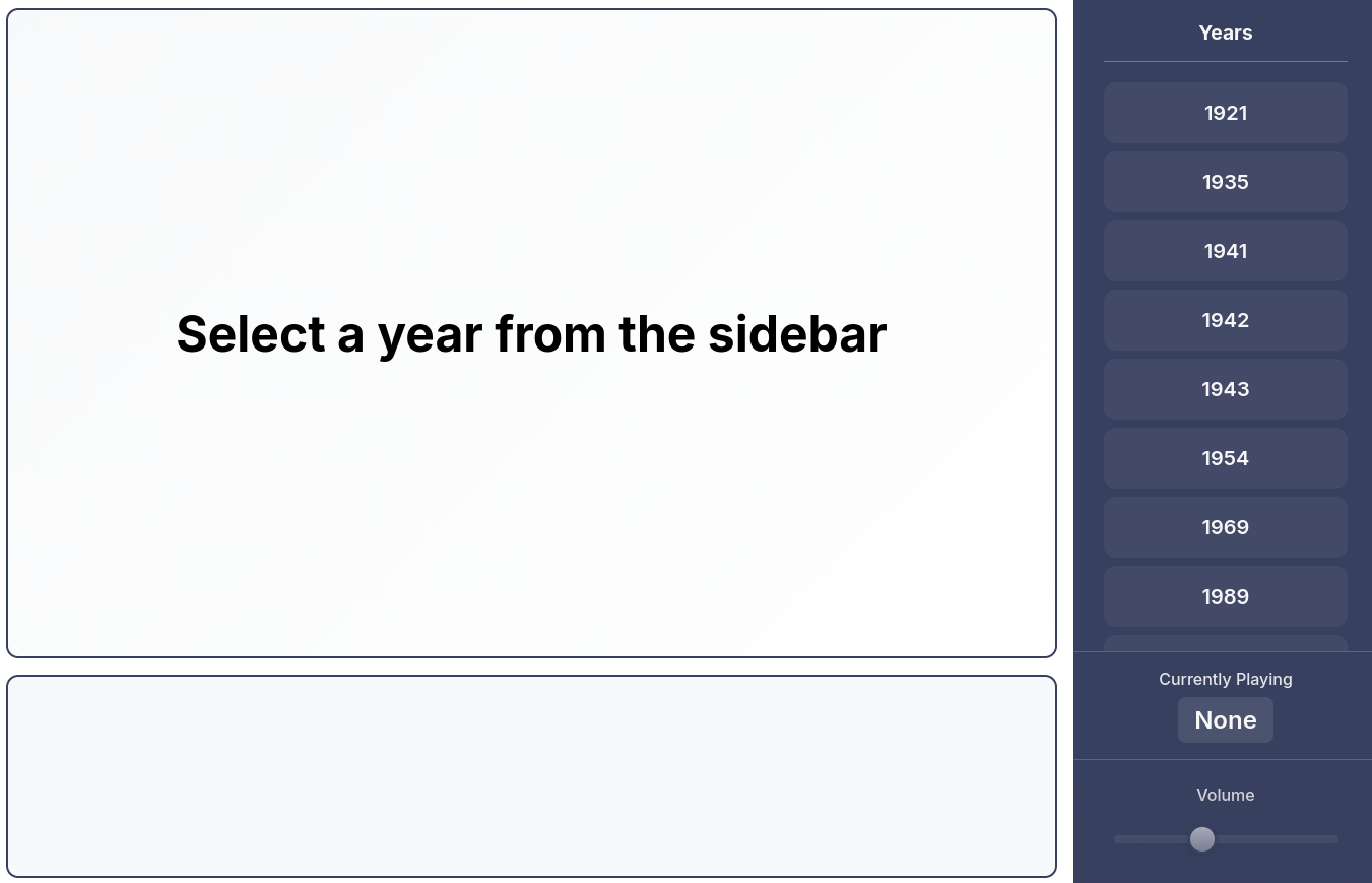
Adding features like volume control on the web page, and currently playing was helpful to learn how to properly do POST requests with an ESP32. I also added the ability to click a audio file in the web app, and then that will queue up on the phone.
Conclusion
Having my family play with the end product has been fun. One of the hardest parts of the project has been getting audio, cutting it down, and finding accompanying photos.
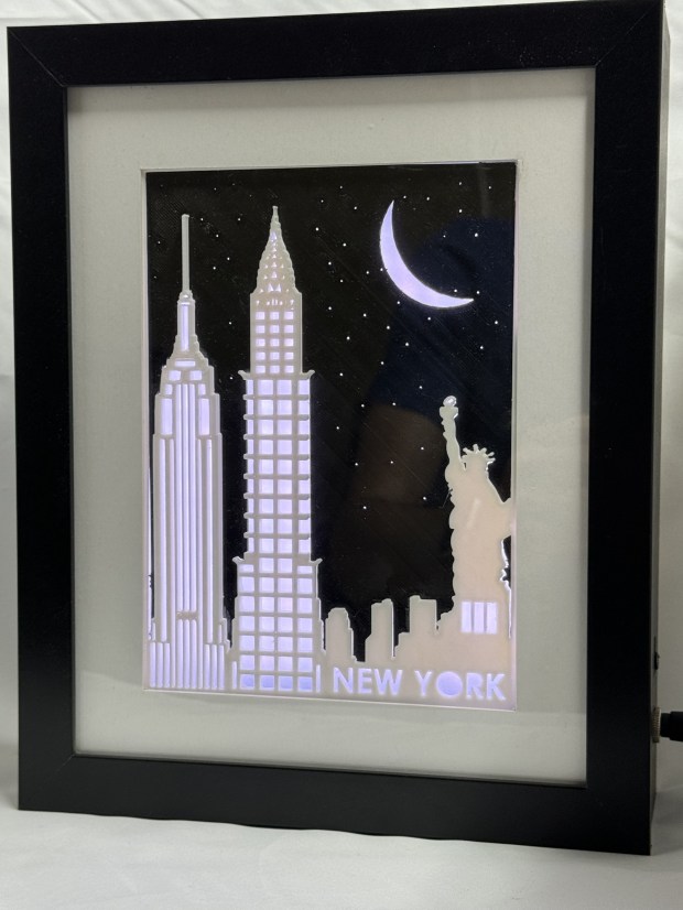
I had a bunch more ideas for the project. Adding a Bluetooth audio output option, photos overlaid on AI-generated period artwork, family tree generator integration, on-device recording capability, support for phone buttons and indicator lights, and standardized metadata schema. I already have spent far longer than I thought on this project, so those ideas will wait for another day.
In the end this was a fun project that I learned a lot of about web servers and audio processing on an ESP32. These chips continue to amaze me in what they can do for under $20. I will probably use that same audio board again, the documentation is bad but now I know how to get it to work. Here is the repo with even more information, the supporting 3D models, and files. If anyone has questions or recreates this, please leave a comment!


")
")
