PDP-8

Building a PDP-11 Kit (PiDP-11)

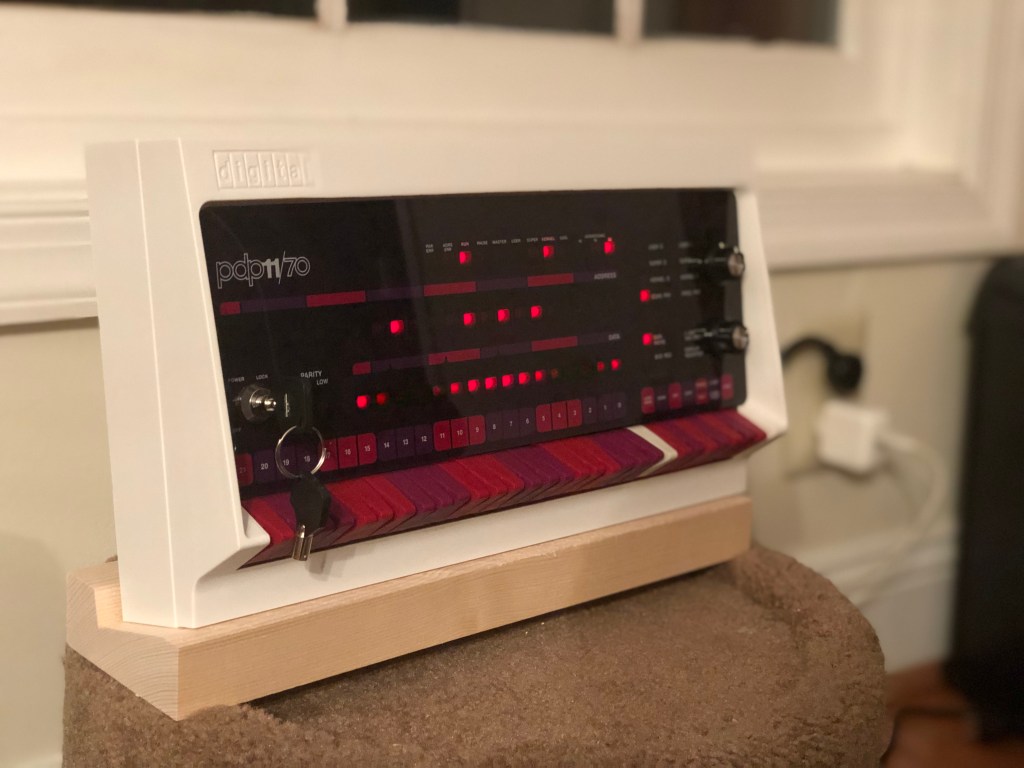
A few years ago I put together a kit from Oscar from http://obsolescence.wixsite.com/obsolescence. It started with soldering, went through setting up a Raspberry Pi image to emulate a PDP-8, and ended with a functioning simulated PDP-8 with working front panel! I was having some issues with one of the integrated circuits; but Oscar, being a great guy, sent me another one and I was able to prove to myself I wasn’t crazy and everything worked. Enjoying the project a lot, I was excited to see he has started production of a PDP-11 kit, this time with a nice plastic injection molded case, and compared to my rev 1 PiDP-8, nicer switches. So I had to order one.

I was able to get the kit working within a few hours of starting, I think part of this is Oscar has gotten better at making these kits; with having the board illustrate where parts go, and having a clean layout, it was fairly easy to put together and solder up. Also my poor soldering skills may have gotten a bit sharper.

While I was at it, I thought I would get my brother a kit so he could get into soldering, which he hasn’t done much of. In going through the instructions I found them a bit light for a novice. To remedy this, I took a bunch of photos during the process and will post them below. The official instructions have more details so I intend just to be additive to those with additional hints, details, and photos.

To start, 30 diodes must be soldered to the board, followed by a few resistors. The tan ones are the 1K ones and go in between some diodes on the bottom row, these spots are labeled “1K”. The 390 ohm resistors go in their labeled spot in the middle of the board. These are put through the board, soldered in, then their legs are cut. Polarity doesn’t matter for these.

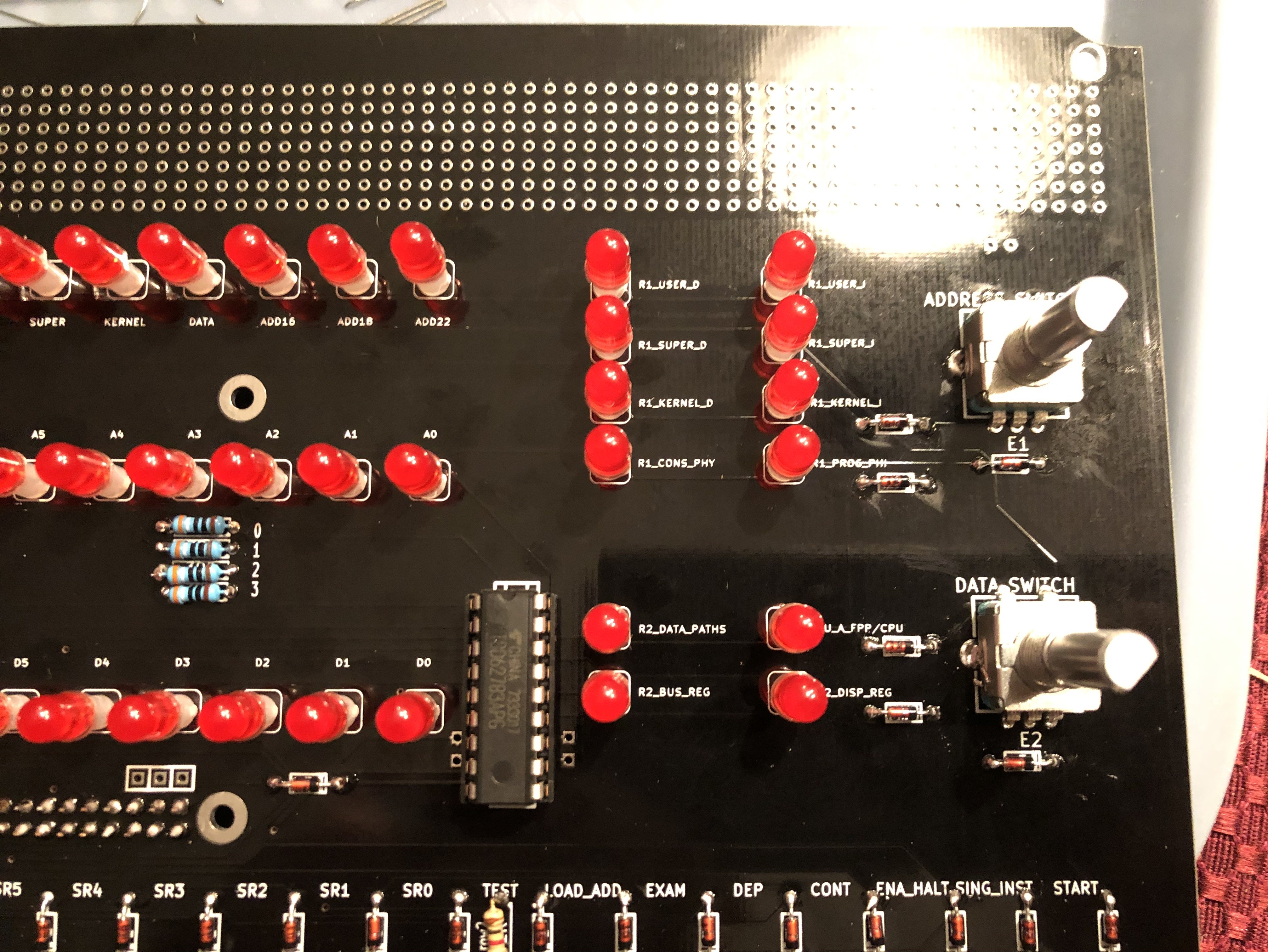
Now the GPIO connector for the Raspberry Pi can be soldered in THE BACK of the board, making sure its flat. Followed by the chip socket that goes on the front, in the middle-ish near the rotary encoders. Don’t solder this in with the integrated circuit in it. Note my board is a newer one with some expansion options that Oscars site doesn’t show, make sure to use the correct chip socket location.

Later photo with chip socket and chip installed

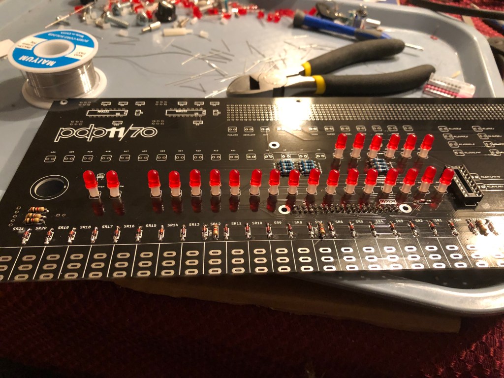
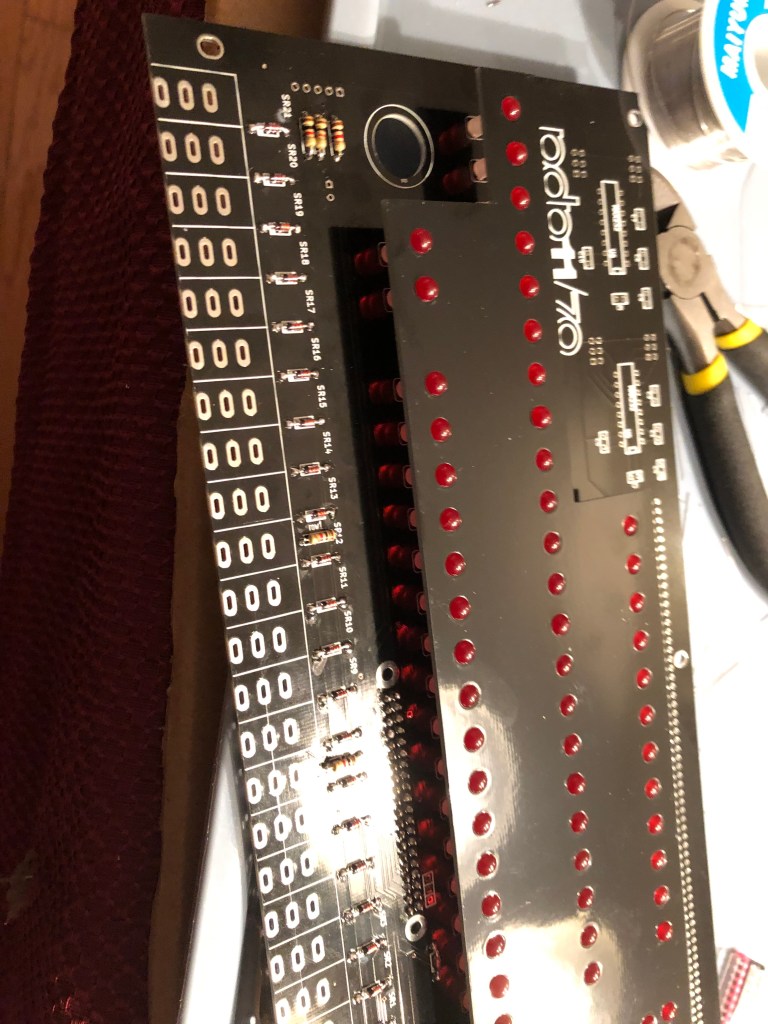
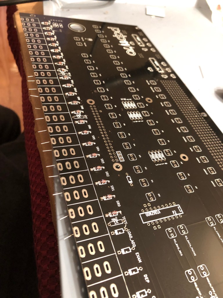
This step is the longest and a bit tedious, you need to get 64 LEDs, each with a little riser, and stick it into the board with the correct polarity. That is long leg matching the icon to on the board, for me it was to the left.

Soldered LEDs with board indicator

Now there is a piece of board that comes with the kit, that can sit over all the LEDs to line them up, and once they are all in straight and aligned, they can be soldered in. I would recommend not snipping the legs off until you have tested and are sure they all work. The last soldering steps are to solder the rotary encoders in. After that put the integrated circuit in the socket, and test it out!

Oscar has a bunch on how to test the board so I will leave that to him. One note I will add, my Raspberry Pi had to be a good amount in the socket before it would work well, but this led to the RJ45 port hitting some of the LED contacts and shorting a row. I found getting the anti-static bag the Pi came in, and placing it between the top side of the Pi and the board solved all these problems.

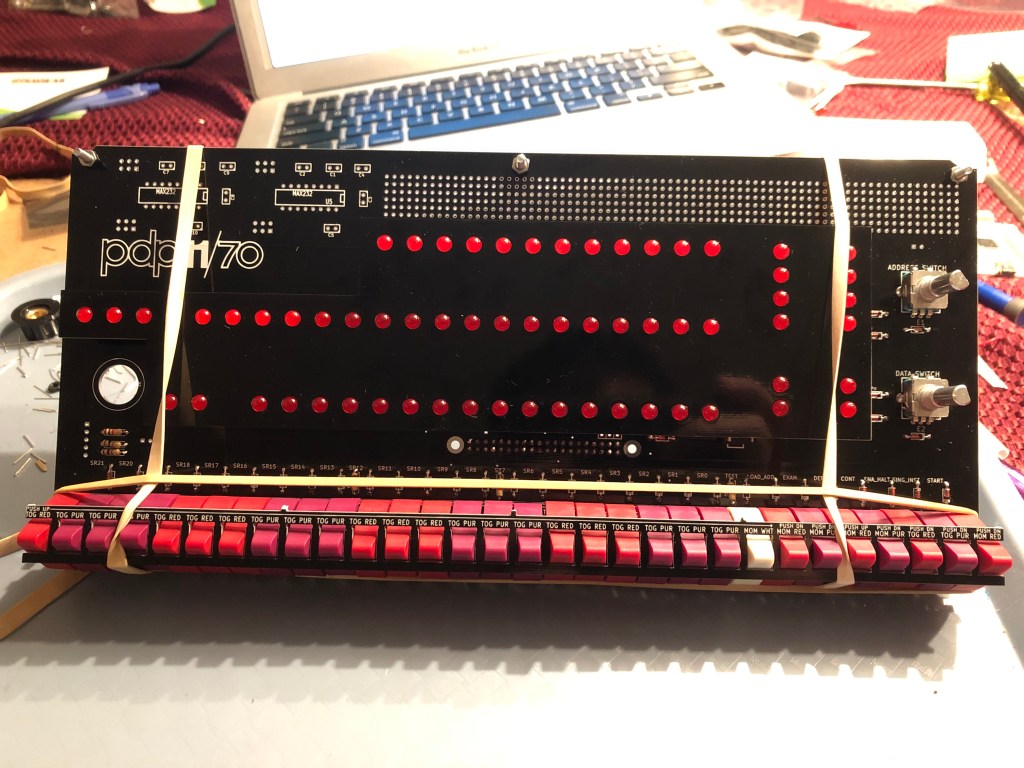
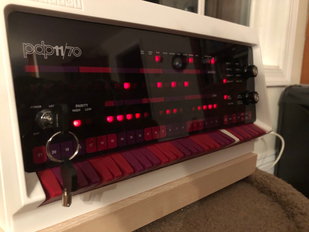
Jumping ahead, I want to mention putting the switches in since this is the one other part of the kit that is a bit confusing and may give people issues. Using the switch lining up tool, that is included with the kit, I found the easiest way to hold everything in place and solder was suggested by Neil over at the PiDP-11 Google group, https://groups.google.com/forum/#!topic/pidp-11/E-RMRVQ15NQ%5B1-25%5D

Neil’s way to hold switches in place

Using this technique, I was able to solder the switches in easily and without difficulty. Follow what the tool says and you should be good. Make sure you are in a well lit room, since in the dark the red and purple can be a bit hard to distinguish.

Using this technique, I was able to solder the switches in easily and without difficulty. Follow what the tool says and you should be good. Make sure you are in a well lit room, since in the dark the red and purple can be a bit hard to distinguish.

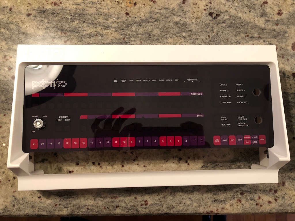
Finishing up, consists of more testing with the Pi installed; then going and screwing it all into the case. Be careful, these don’t need to be screwed in very tightly and you can fairly easily crack the acrylic (this I have learned from other projects in the past).

This was a fun kit, and I hope Oscar keeps making more of them. If you have any issues head on over to the PiDP-11 Google Group, and if my guide helped out out, please let me know in a comment below. 🙂

Building a PDP-8 Kit

A bit ago I picked up a PDP-8 replica kit, the PiDP-8. A kit can be picked up here http://obsolescence.wixsite.com/obsolescence/pidp-8-get-one . They are under $200, and I always found older computers interesting so I thought I would give it a shot. I also find The Digital Equipment Corporation and interesting tale of a far gone computing era. (There were t-shirts with the DEC logo on Amazon, but they are gone now)

IMG_4855.JPG

The kit itself is a little smaller than the original control panel; photo from the creators blog above. This is not a real PDP-8, it is a front panel with a Raspberry Pi on the back of it. The Raspberry Pi has an image that is on the user forums (which are incredibly helpful as well as a nice community) which boots very quickly and dives right into the modified emulator. The design is wonderful and just uses the pinout on the Pi.

I got the kit, then ended up moving across the country and did not setup the kit for several months. When I got to building the kit (2015 version, pictured above) it was 2016 and instructions were up for both version. Not many differences except the switches, and how they are mounted. My version needed me to remove pins from each switch then mount each on a rod to keep them aligned. The 2016 version also has more authentic looking switches. I got the switch rod put together with no difficulties.

Then it was down to soldering the trillions, well it felt that way, LEDS to the PCB that came on the kit. Small soldering is not my favorite thing, so this took a bit; but in the end it was done and I was happy with it.

I wanted to test my soldering skills, or lack there of. I plugged the Pi in, and started the image. A few of the lights dimly came up, the rest of them just were dead. Darn this means somewhere it’s broken. I did some traces with a multi-meter, and couldn’t find the fault. Then I realized while it was plugged in the one integrated circuit that handles the LEDs were was getting very hot. I emailed Oscar who made the project and he quickly responded and said it sounded like the integrated circuit was dead and he would mail one the next day or so.

He was extremely helpful and kind, and I got the new chip a few days later. I had to go to Radioshack, (I was surprised I could find one! And its no longer there a few months later) to get a desoldering wick. I haven’t used this before, but it helped me remove the old chip. I soldered the new chip in, and powered it up. Instantly it all came online! I wanted to check all the LEDs, to verify if the OS was keeping some off, or if the circuit was bad, I got a diagnostic program that was written for this system. It did indeed show there was a error, and after resolding a small point then everything was working!

Now that the system works, and I sized it in the box; it was time to paint the switches! I covered half of them with painters tape and painted some brown. Then later did another coat. Then did the white ones so they were not off white or having the red dots on them.

After it dried, I cut a hole in the side of the case so that I could access the USB ports of the Pi. I just had a tiny hobby hack saw and a drill, these were not the best tools to cut the hole but it worked out. I also put electrical tape over the edges of the hole to cover up my handiwork. Then I mounted the PCB with wooden blocks for support into the box. I got some velcro with tape on the back so attach the front panel; that way I can remove it whenever I want for service and easily reattach it.

I got a power switch that is inline with a USB cable. That way I can have a switch to power on and off the device. Then I thought the blinky lights were neat, so I mounted it on my wall for now. It boots directly into OS/8 and in idling does a little light show.

20160525_150912714_ios

The project came out well, and I am excited for Oscar to release his PDP-11 clone he has been working on in the background. I haven’t spent that much time programming it, but it is nice to have a piece of computer history above my desk. A big part of this project has been the awesome community over at the forum https://groups.google.com/forum/#!forum/pidp-8 and the kindness of the project owner and his willingness to help. Oscar’s blog has some cool stuff as well, http://obsolescenceguaranteed.blogspot.com/ .

Next I want to do an Altair 8800 kit, while I wait for the PDP11 version! https://www.altairduino.com.

Update: The Altair-Duino! Altair 8800 Kit