For the LAN Before Time, my retro rack, I wanted to mix the most diverse set of CPU/OS/Networking I could find. There are not a ton of networking standards out there, as Ethernet took over so quickly. One that has always interested me is Token Ring, IEEE 802.5 standard, mostly from IBM as a competitor to Ethernet. Token Ring went through many transitions in its time on the scene, from speed changes to connector changes, lasting from the mid 1980s through the 1990s.
Connectors
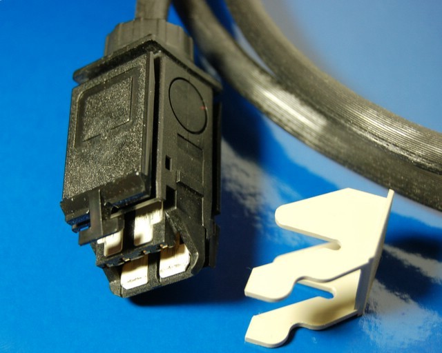
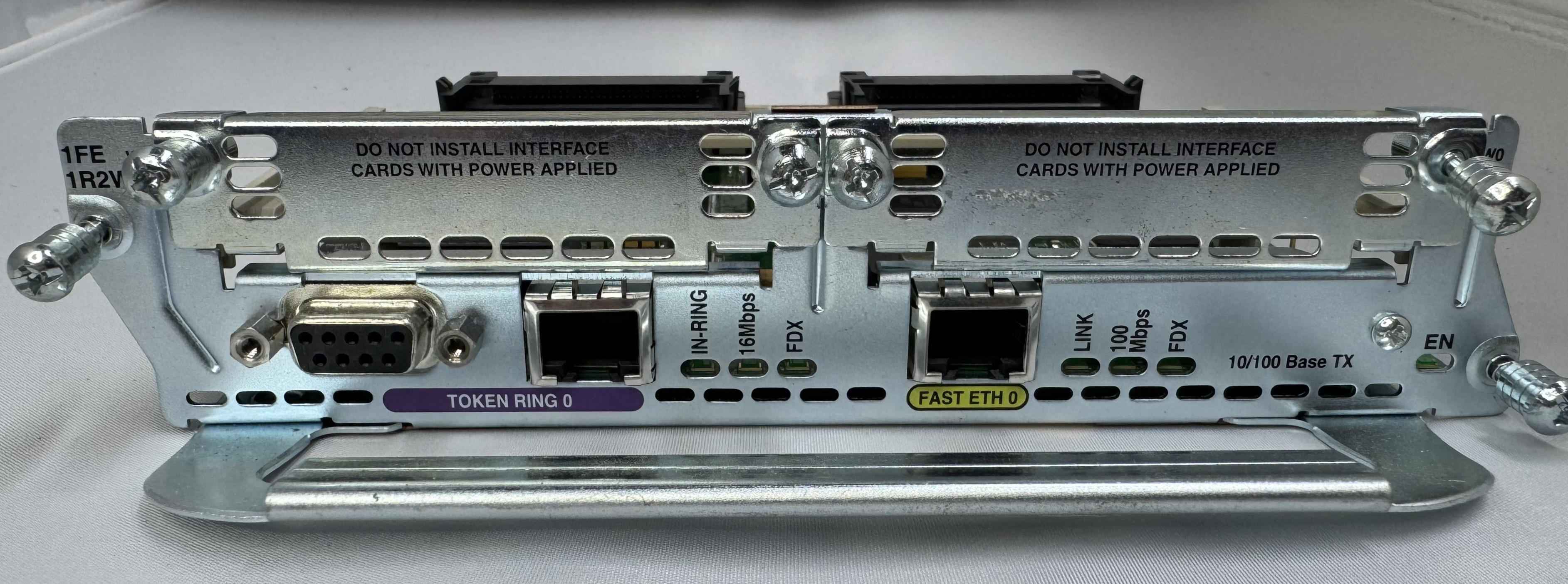
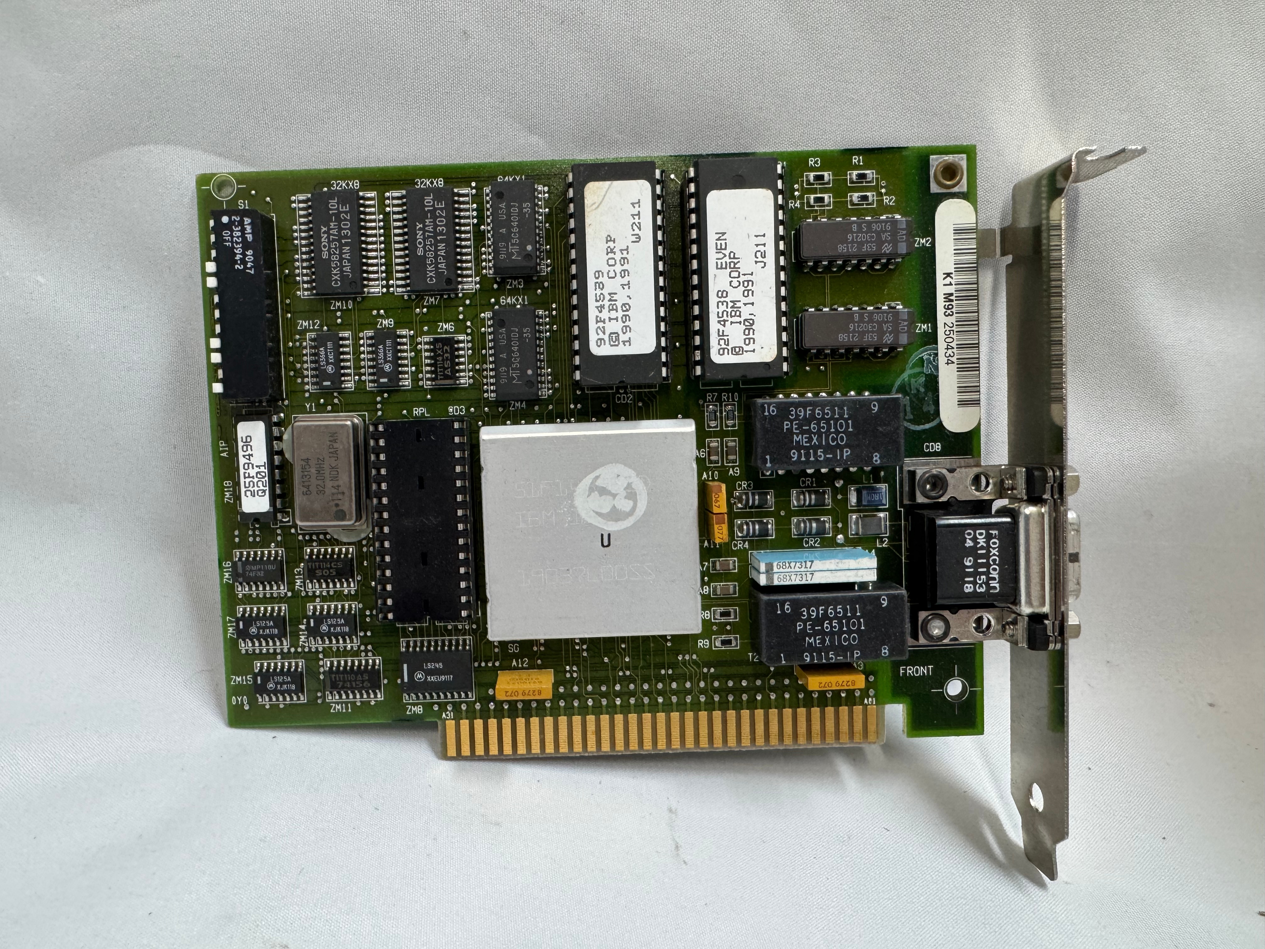
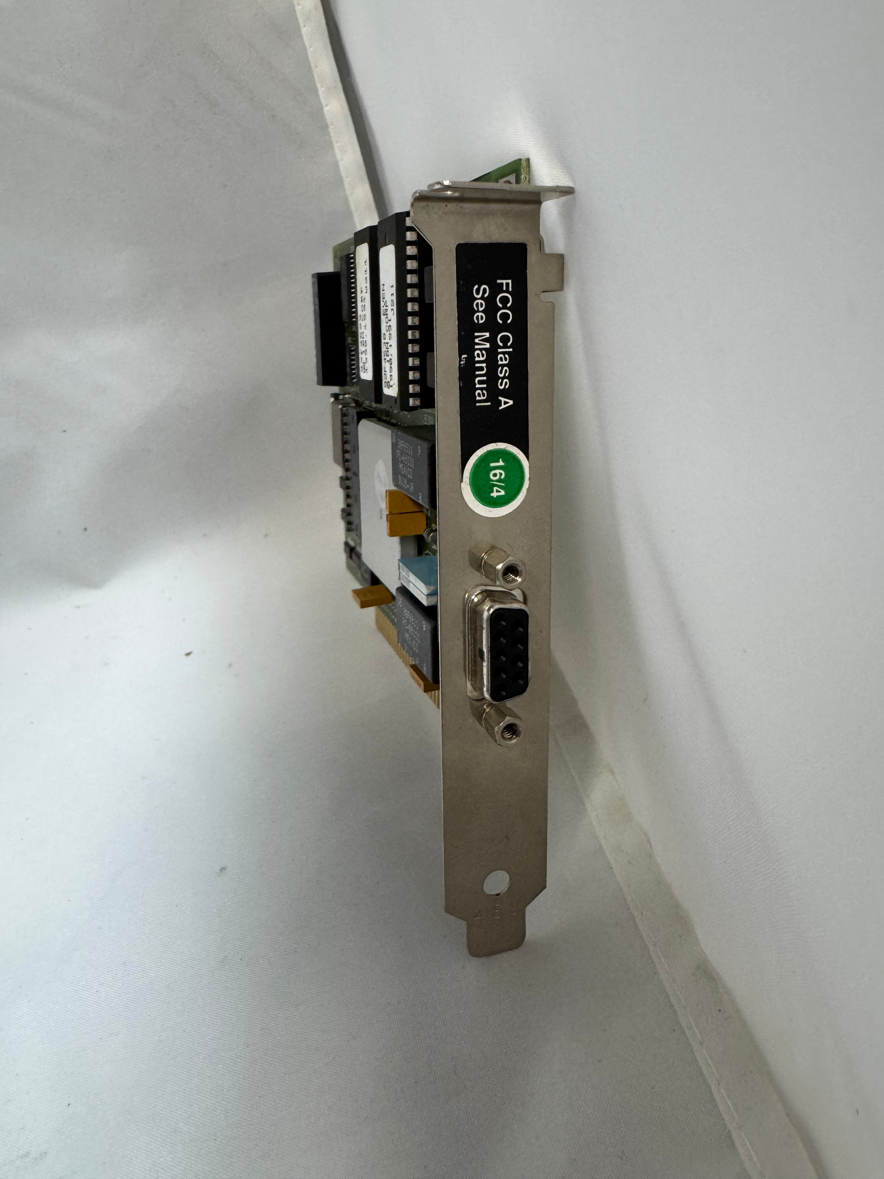
The protocol started at 4mb/s (megabits a second), with the computer having a DB9 connector going to a giant 4 pin plug.
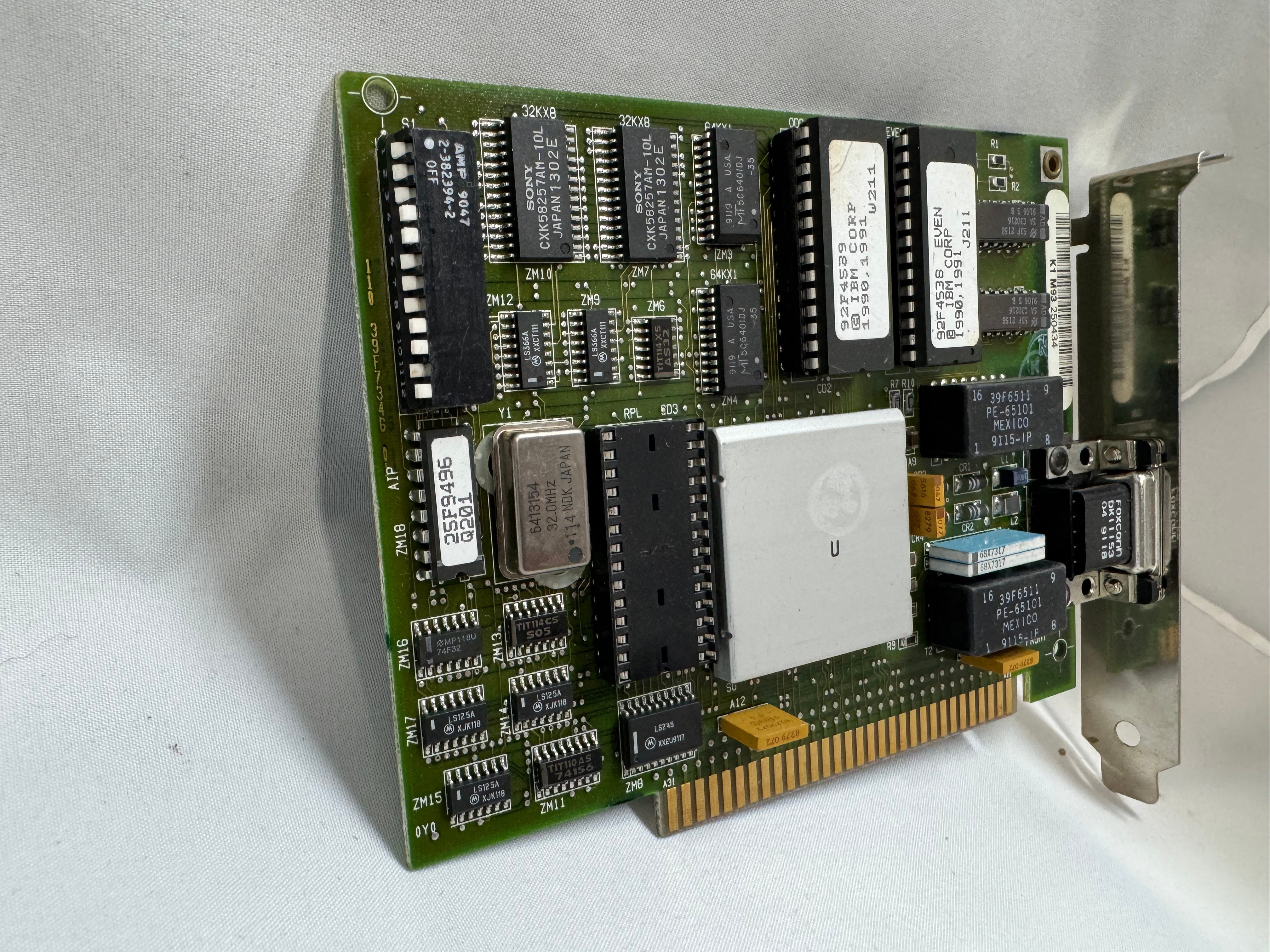
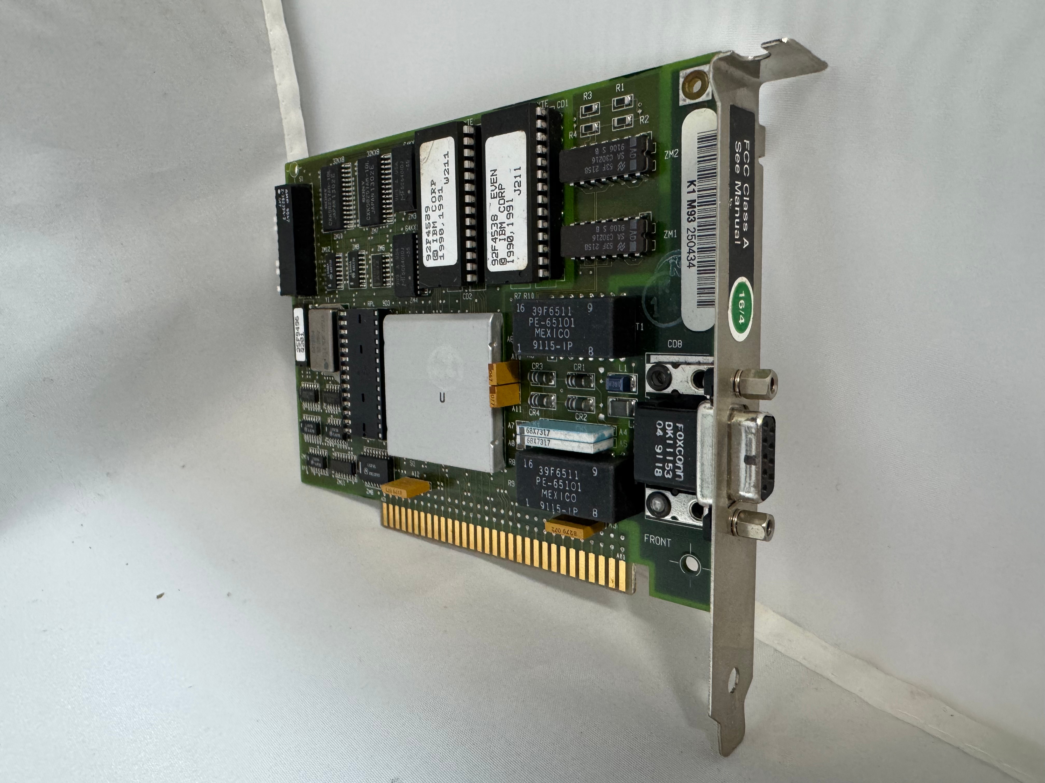
Later 16mb/s was added. Most of the cards you will find are 4/16 cards.
The physical connector, and connection speed are independent, you can use either the DB9 or RJ45 connectors to run 4mb/s or 16mb/s.
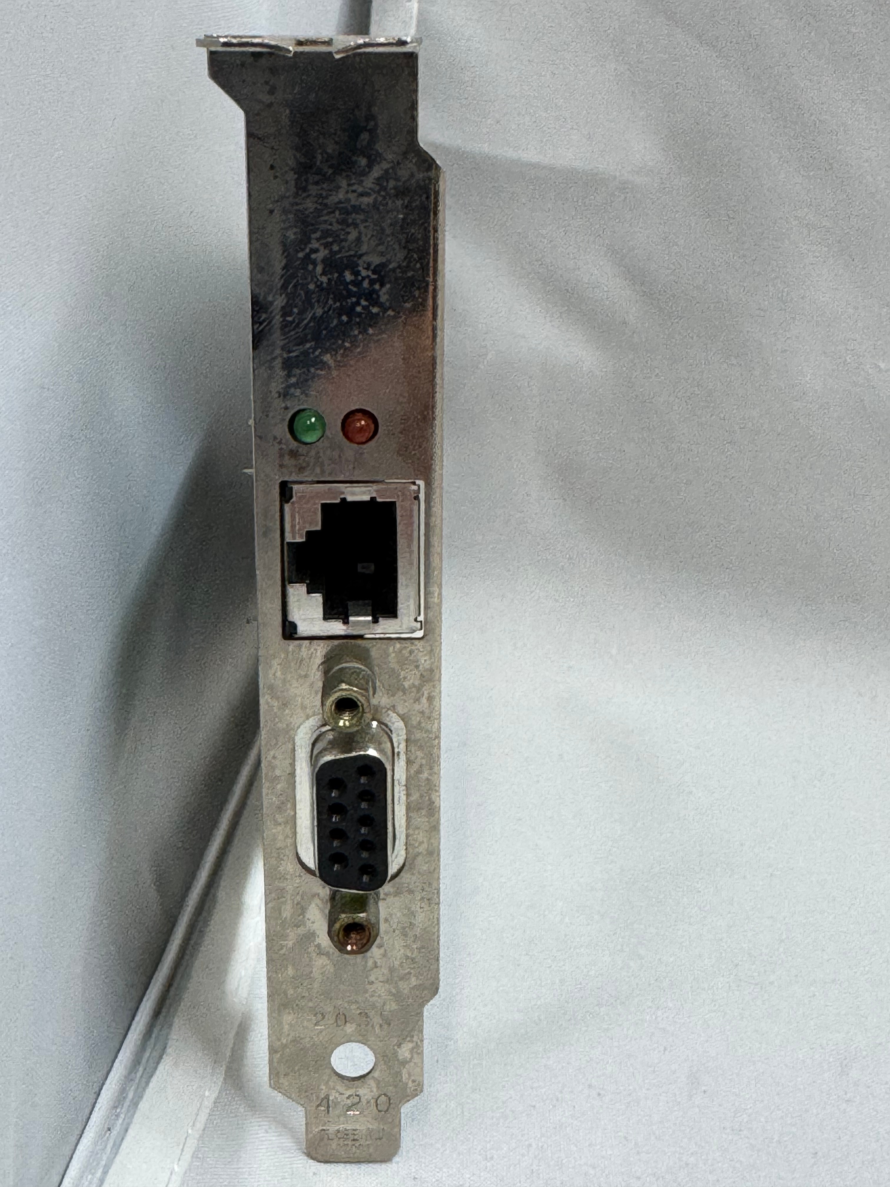
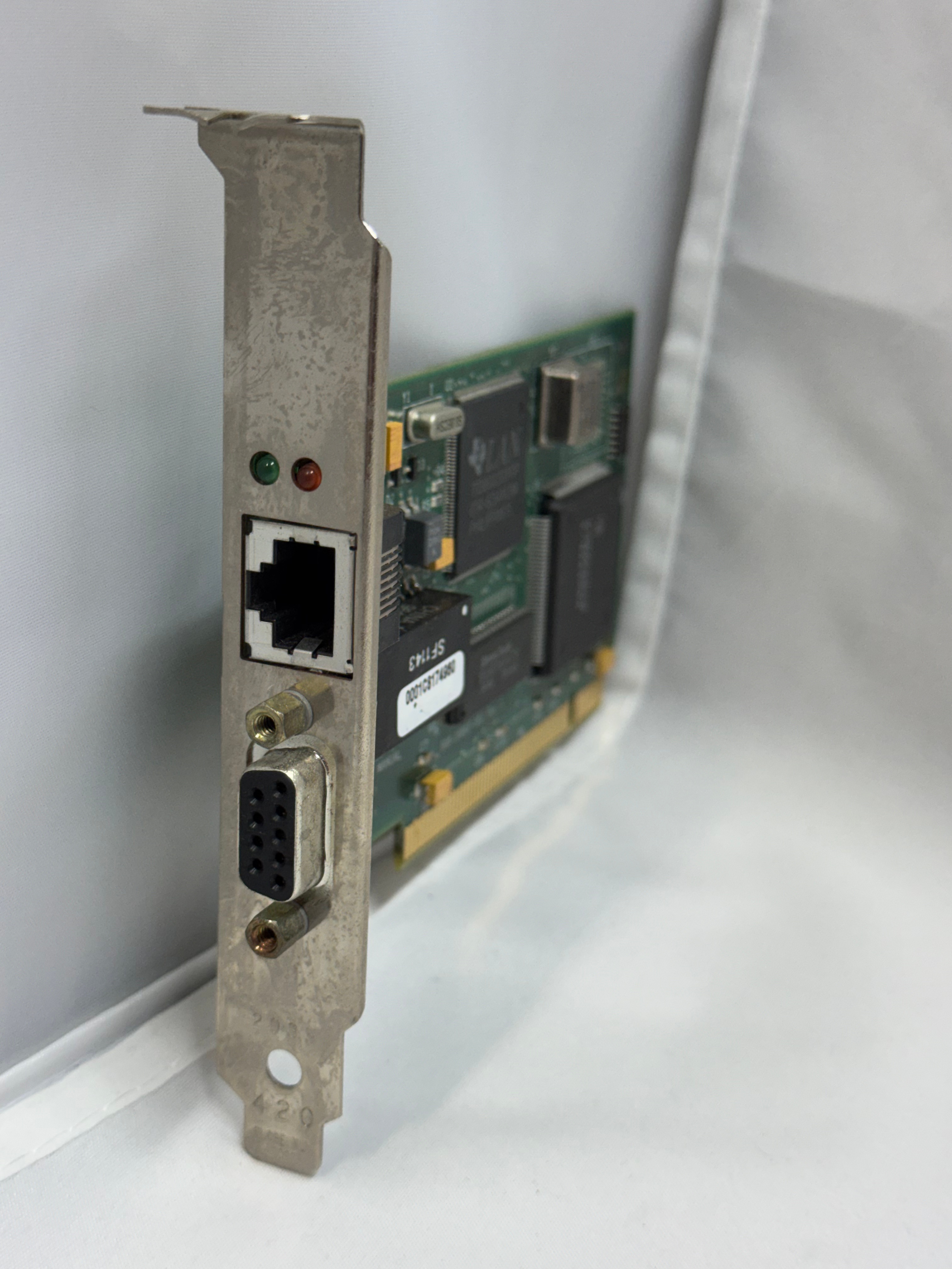
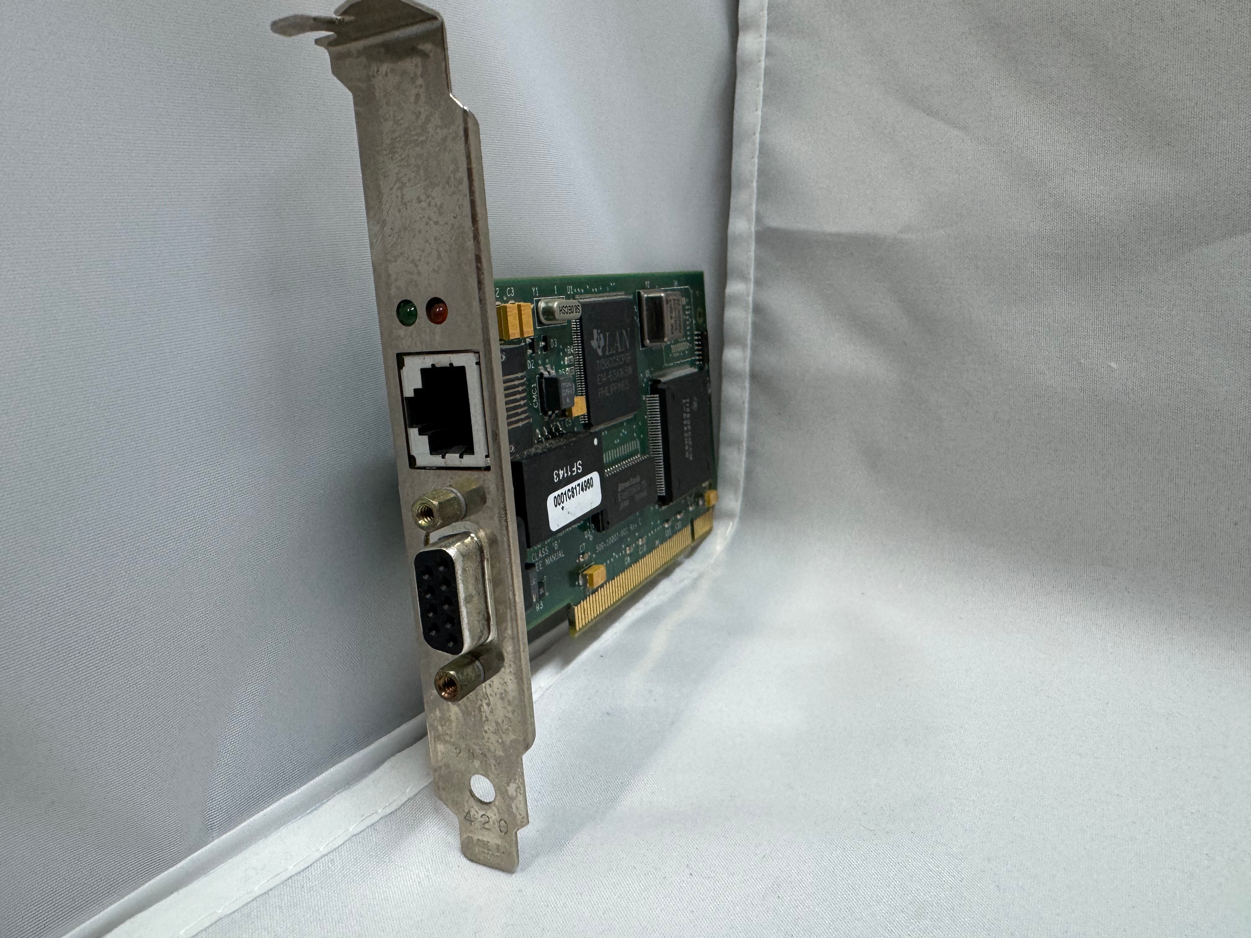
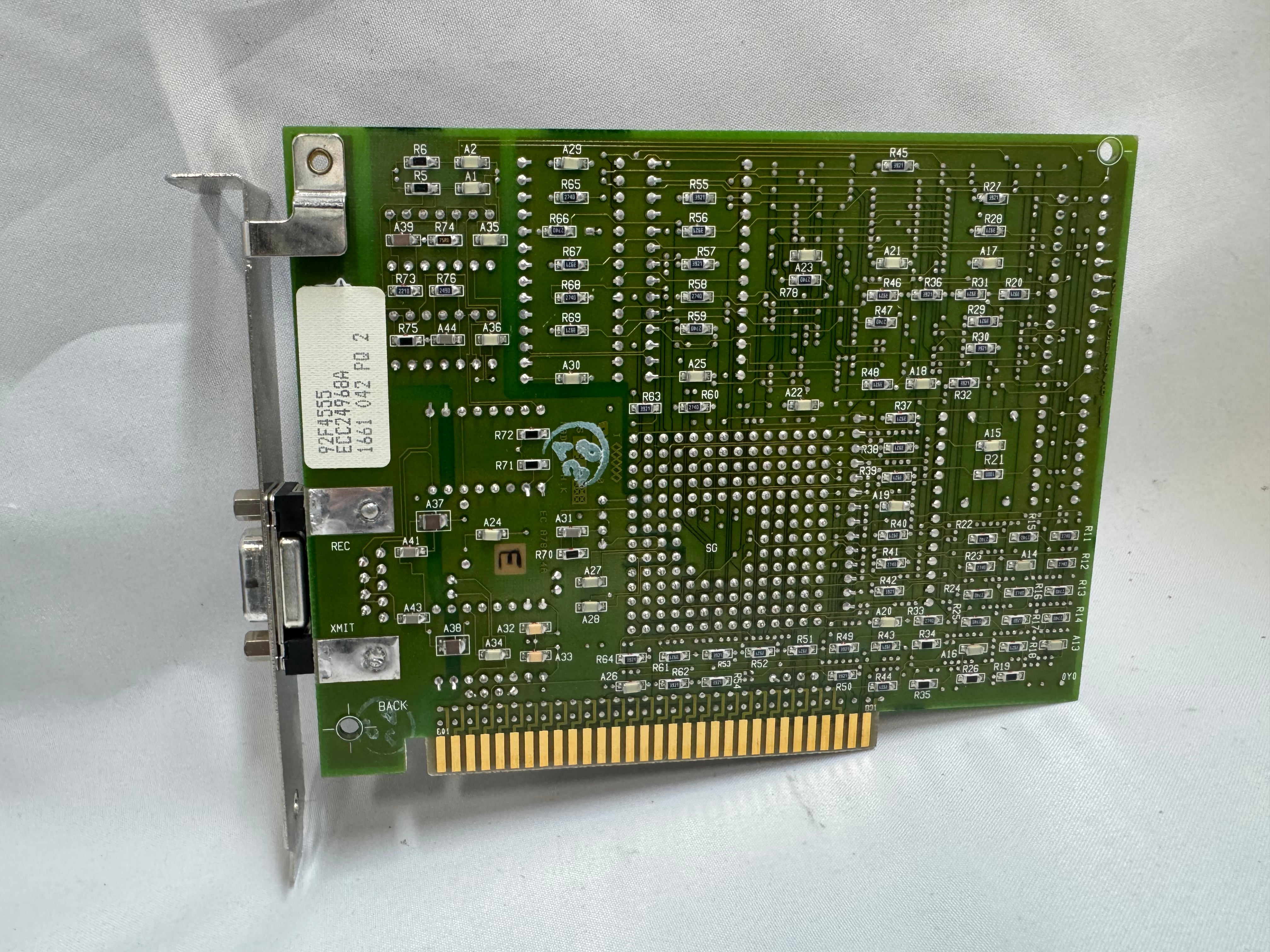
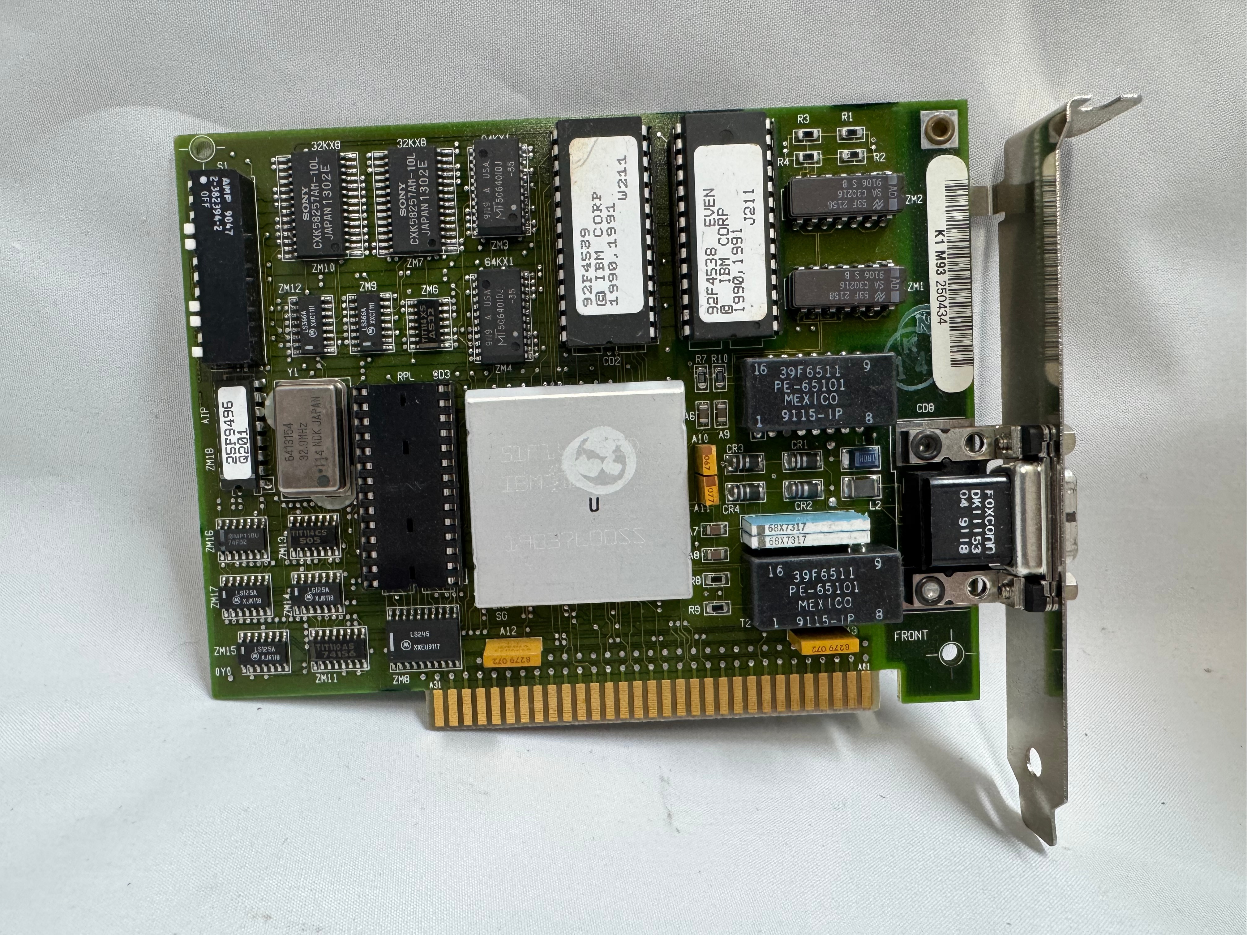
The cards started in the ISA era and later continued into the PCI era. The connector also evolved to a standard RJ45. There were adapters to go between the older connectors and newer ones. Later cards would include both DB9 and RJ45 connectors. With RJ45, only the middle 4 pins were used, but in a straight through way, allowing normal Ethernet straight through cables to be used.
In the last updates to the protocol, 100mb/s Token Ring was added, but by the time that came out Ethernet had taken much of the market share. And finally in 2001 a 1000mb/s standard was created, but Wikipedia says no devices ever came out for it.

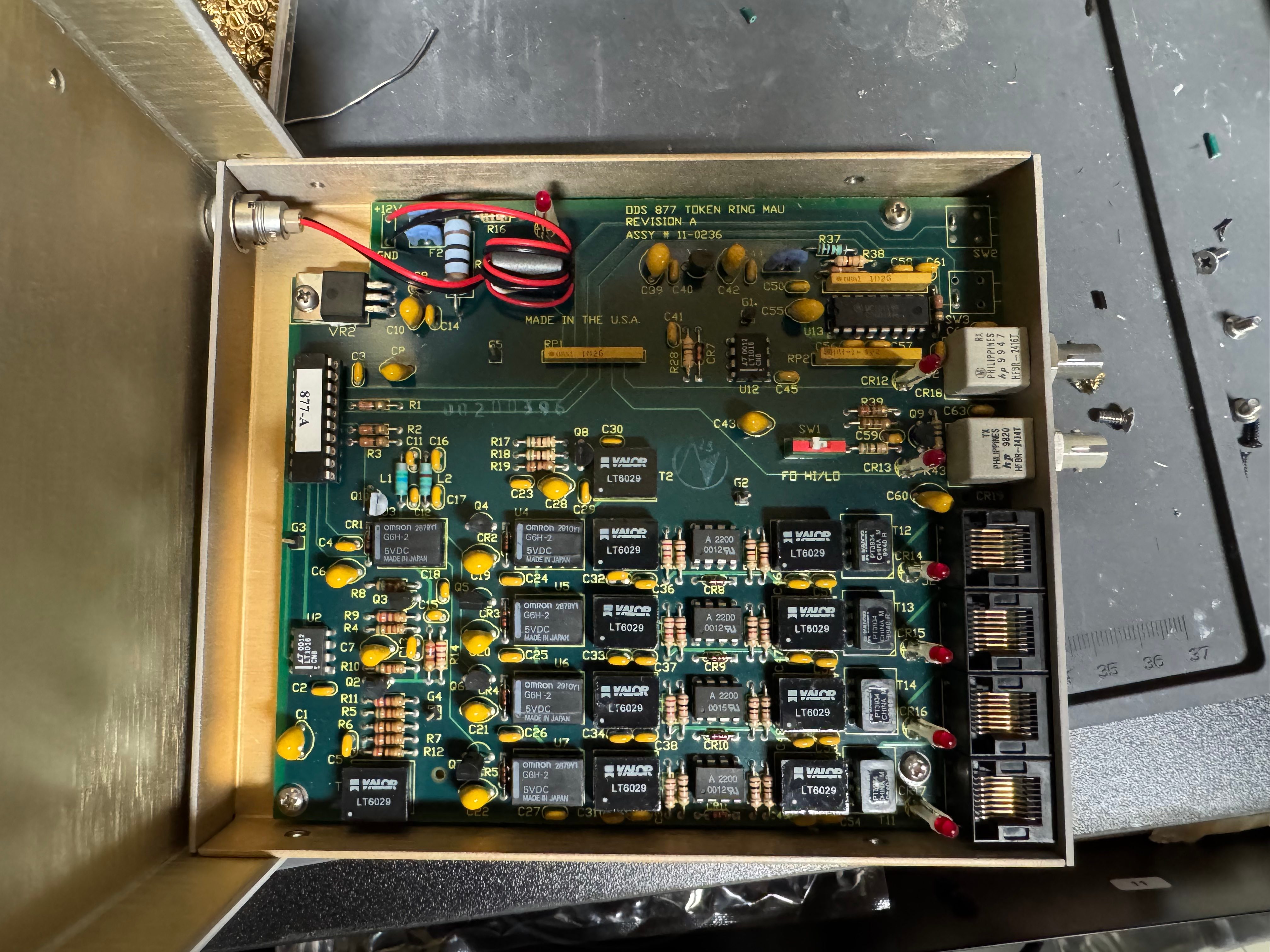
MAUs
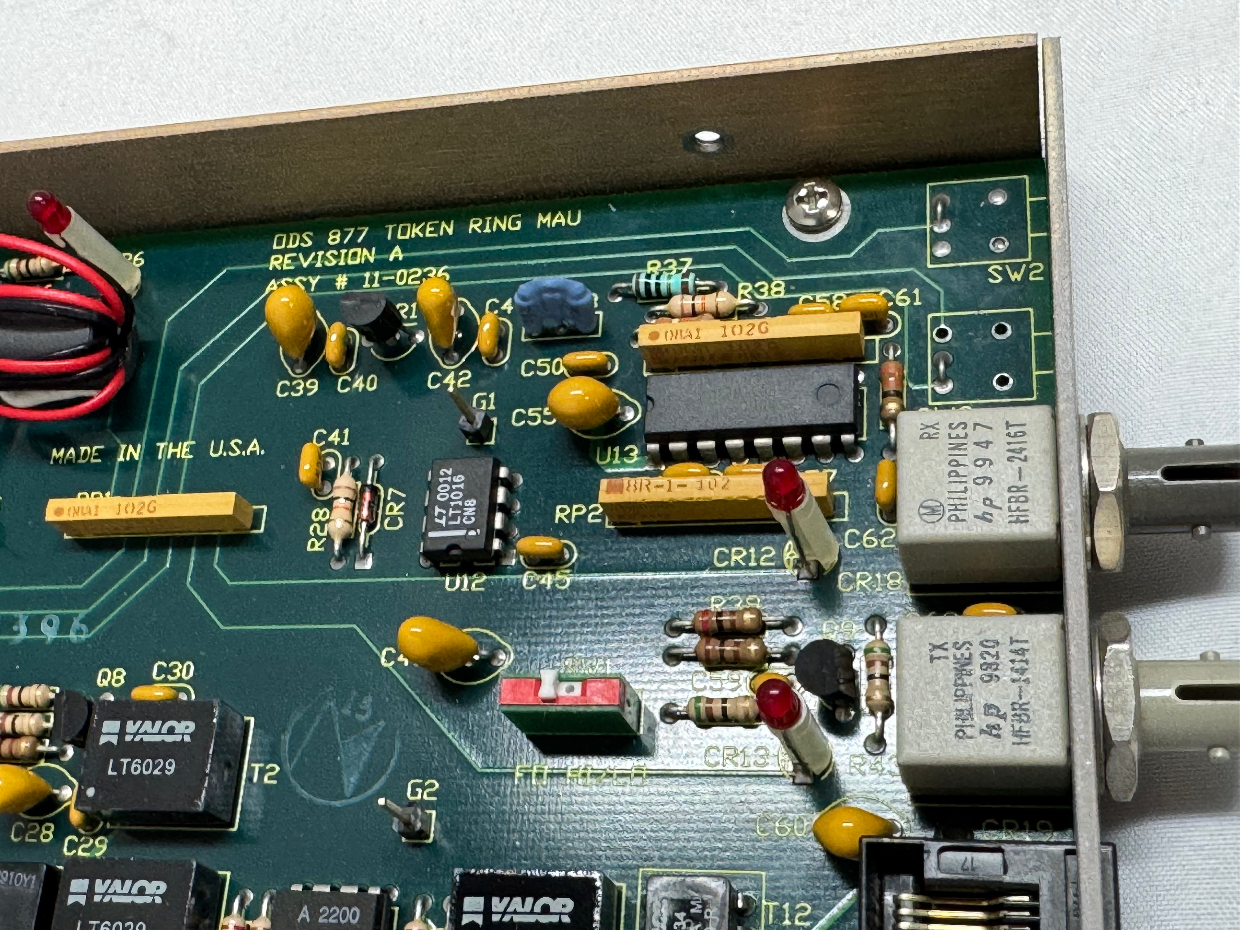
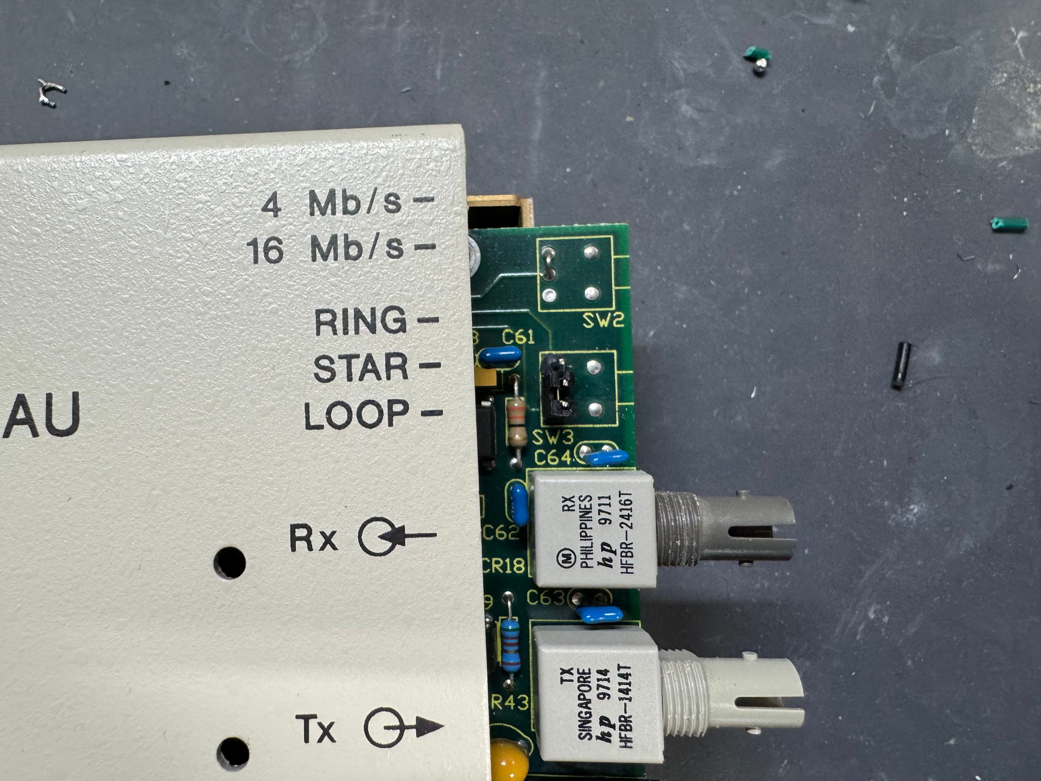
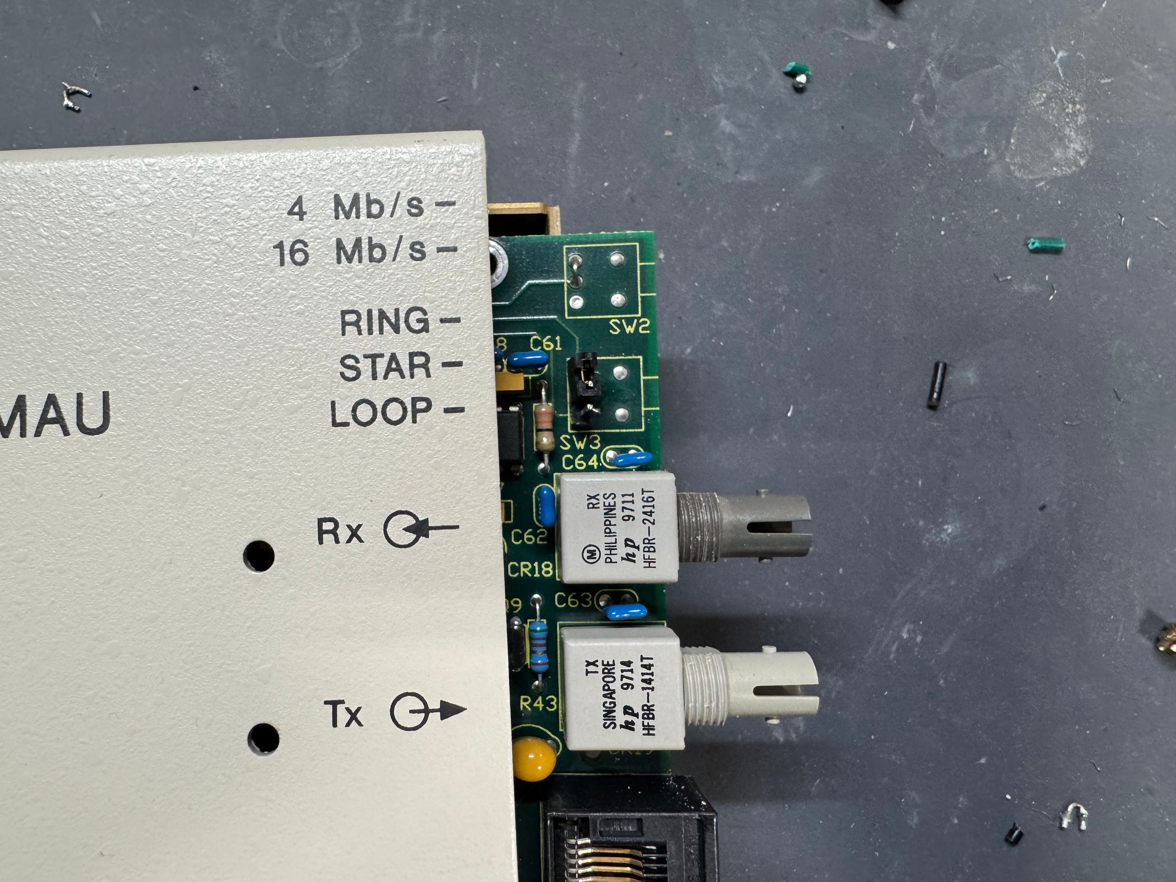
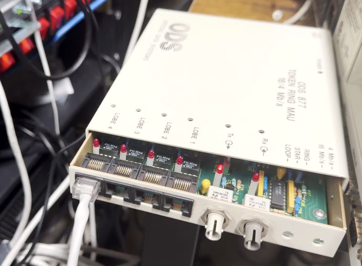
Unlike Ethernet, Token Ring cannot connect two computers directly. You need to go through a Media Access Unit, or MAU. These units control ports going in and out of the ring. They can be thought of like an Ethernet hub or switch. The Token Ring itself also needs a terminator on it. Later models contained internal terminators if put into a specific mode. There are MAUs with the old large IBM connector, and there are newer ones with RJ45. There were adapters between any of these connection types for networks in transition.
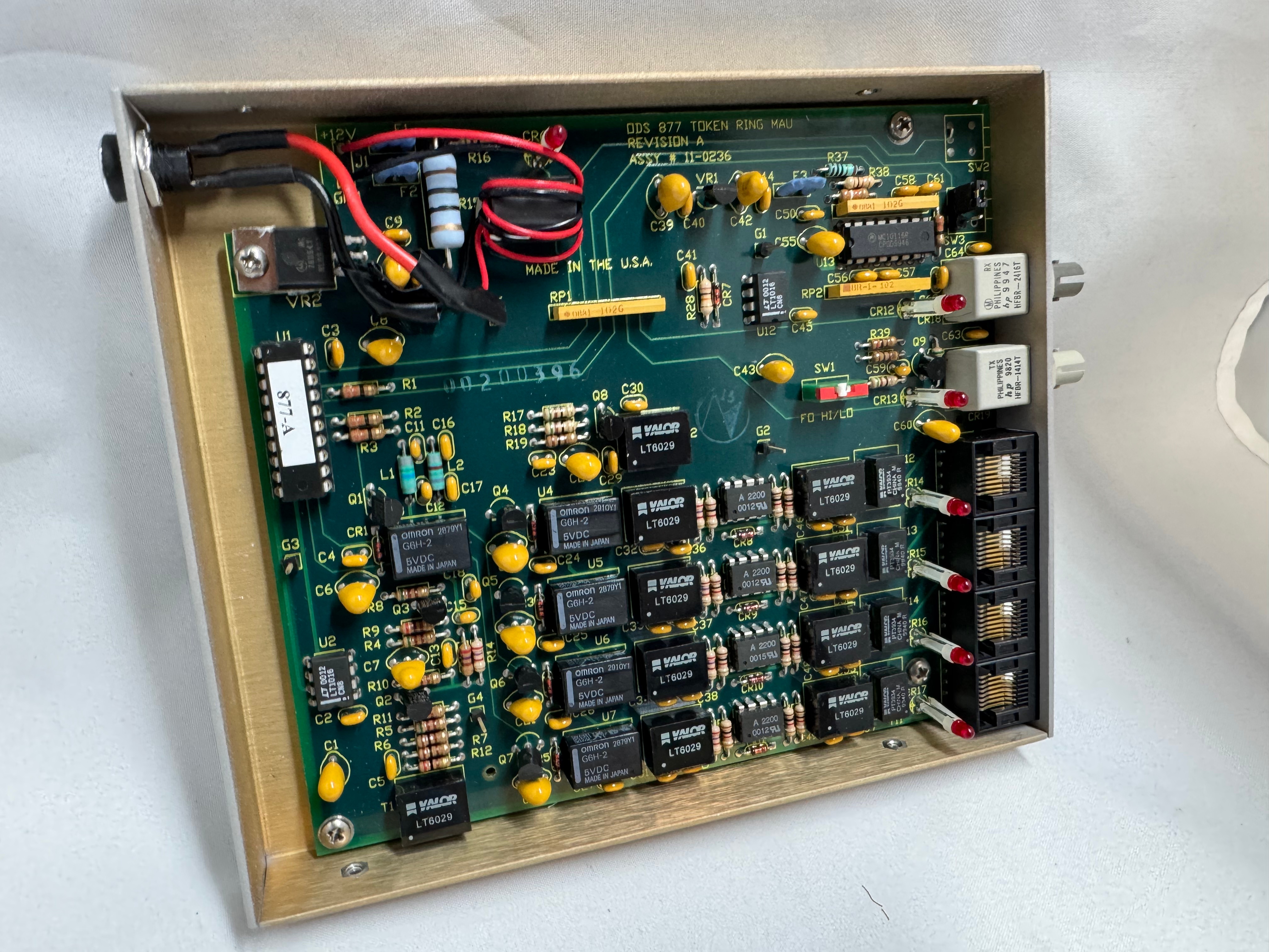
My MAU Journey
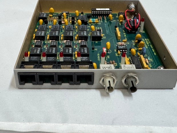
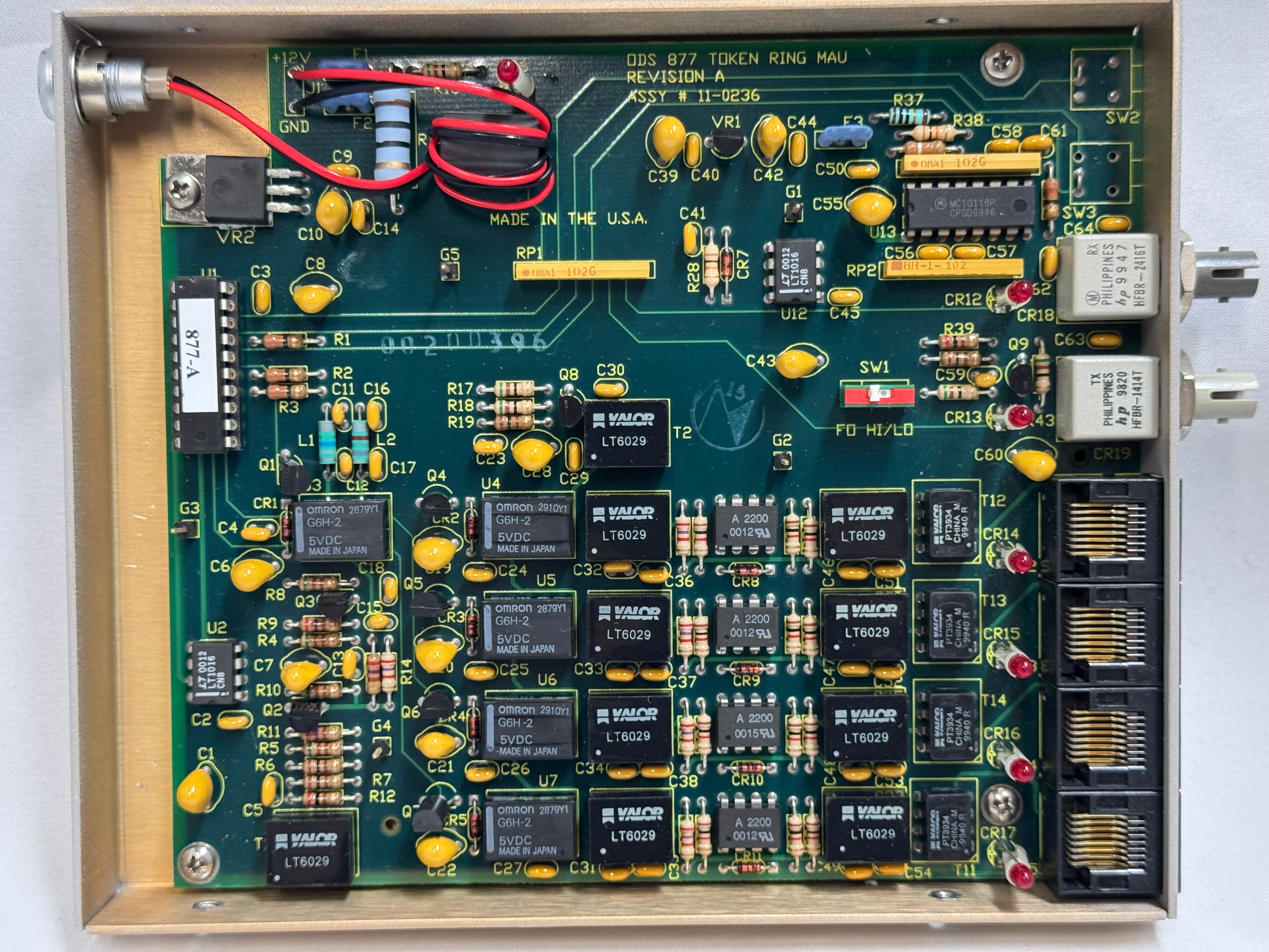
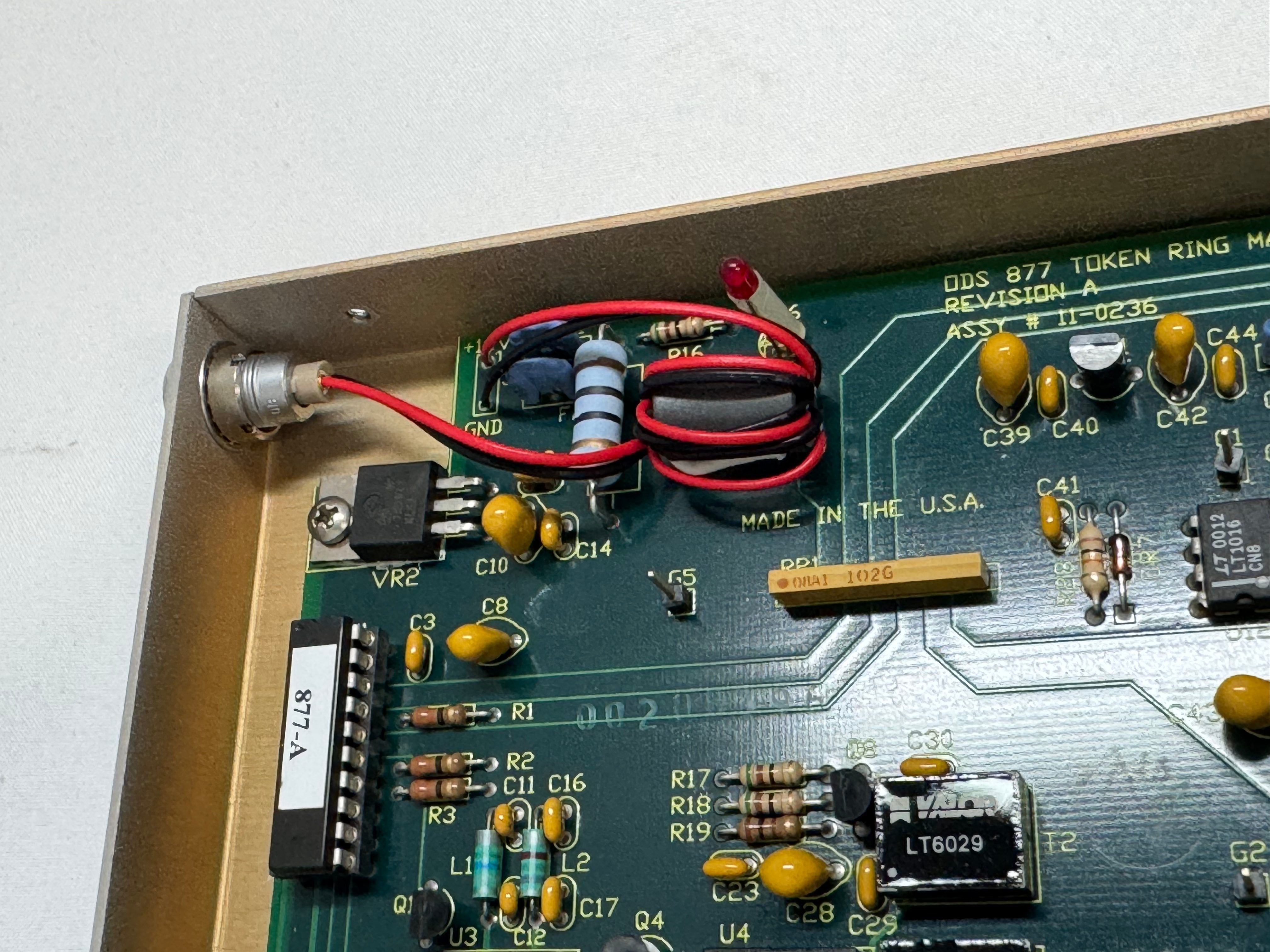
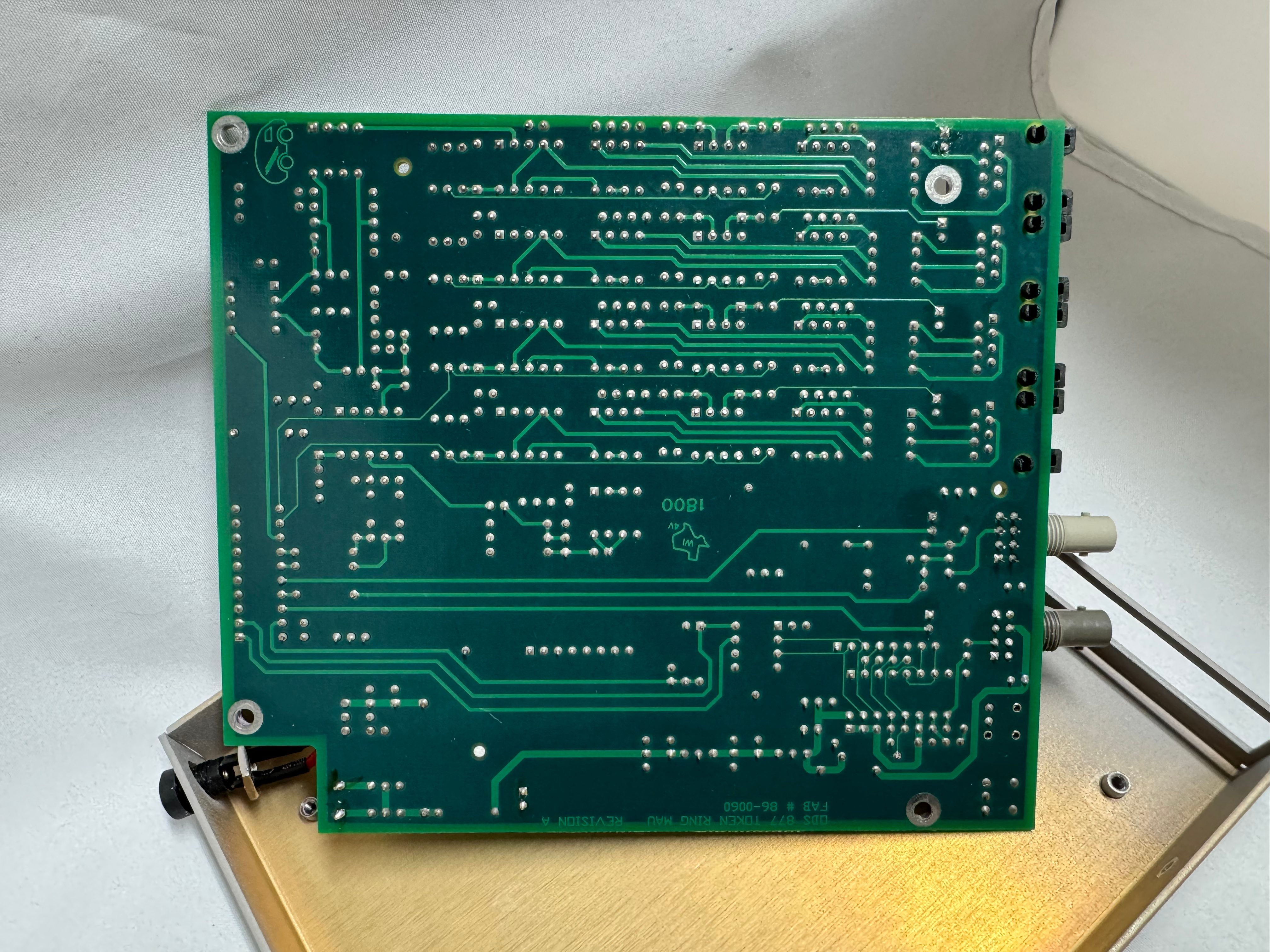
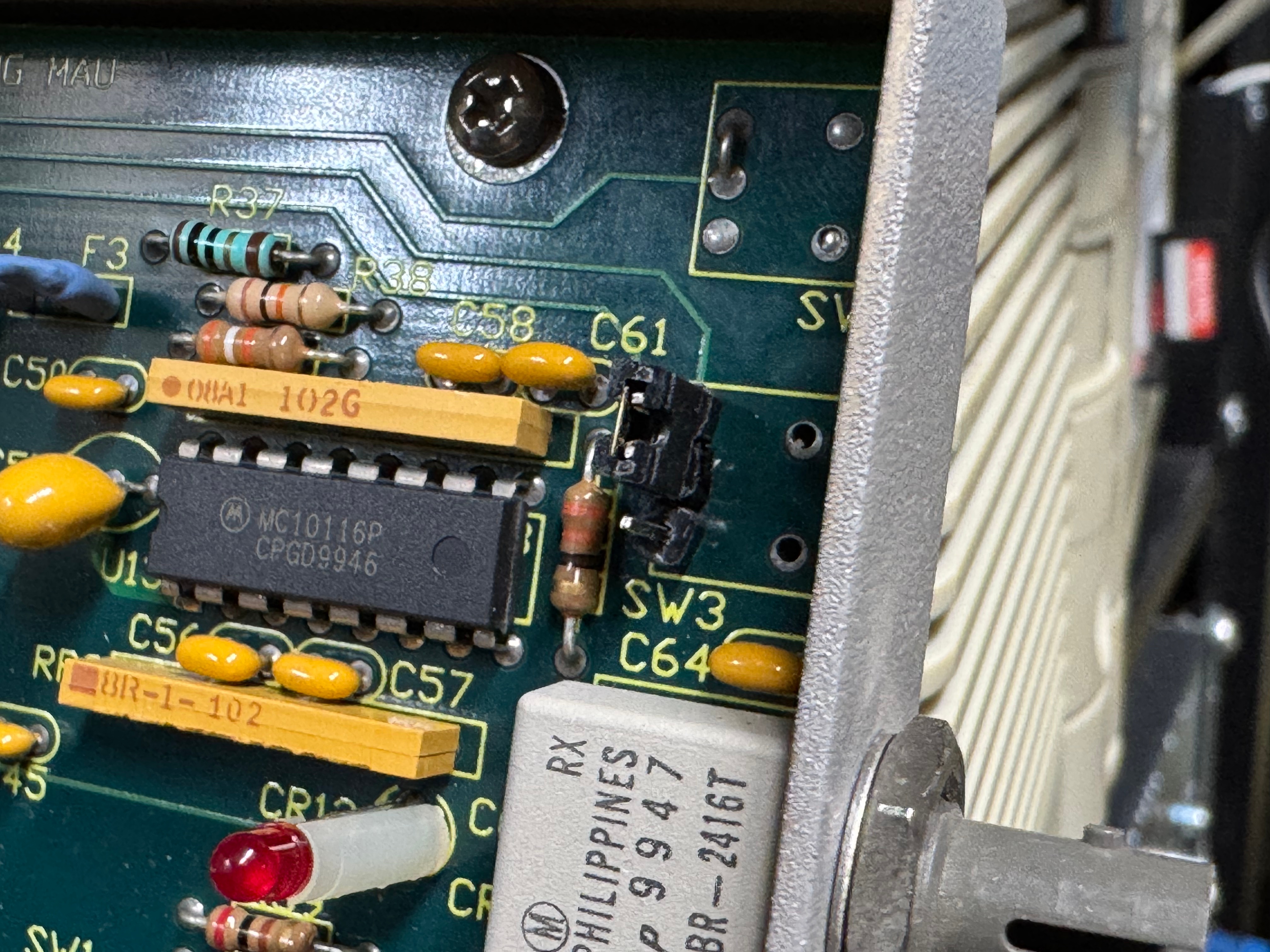
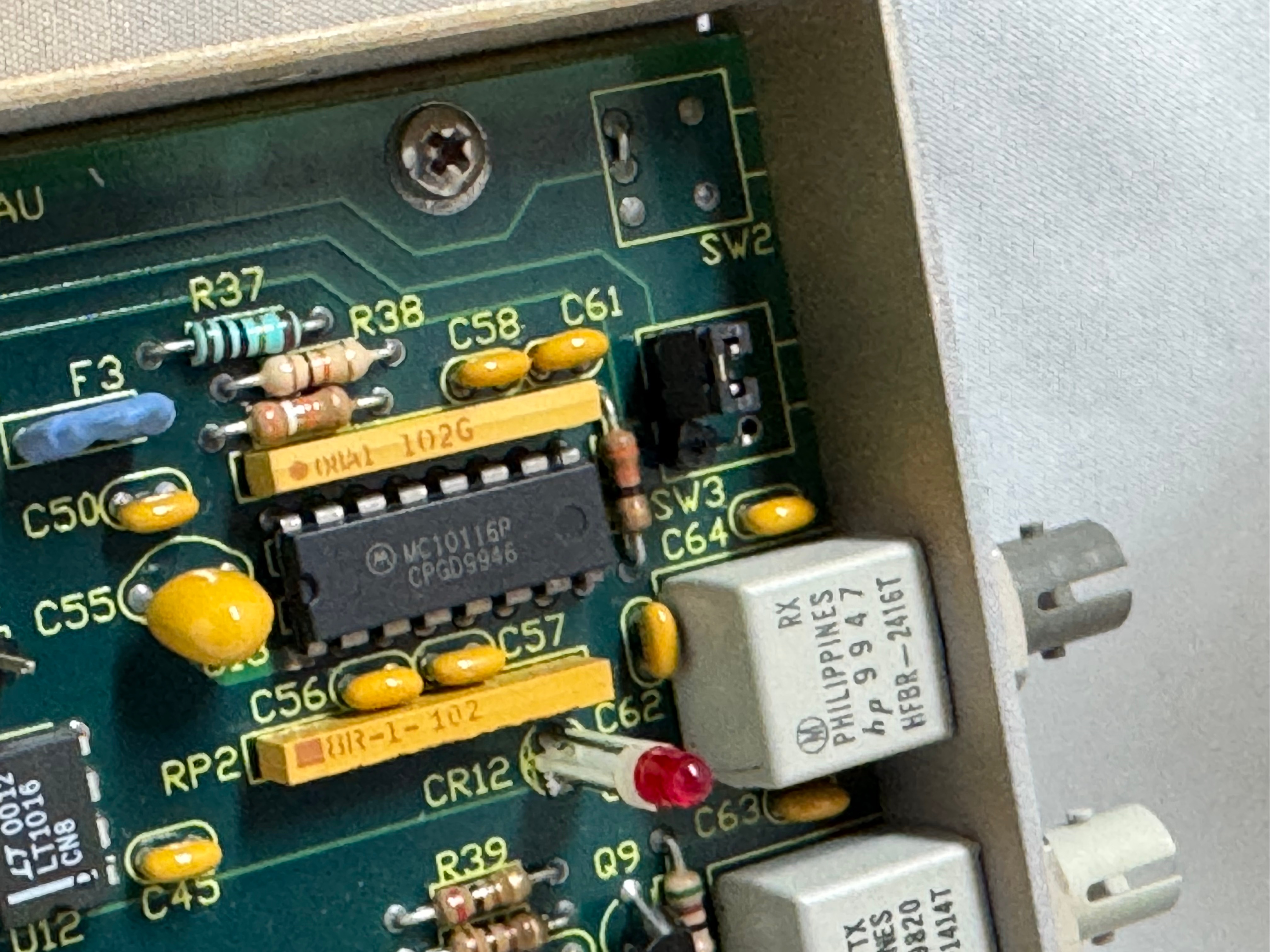
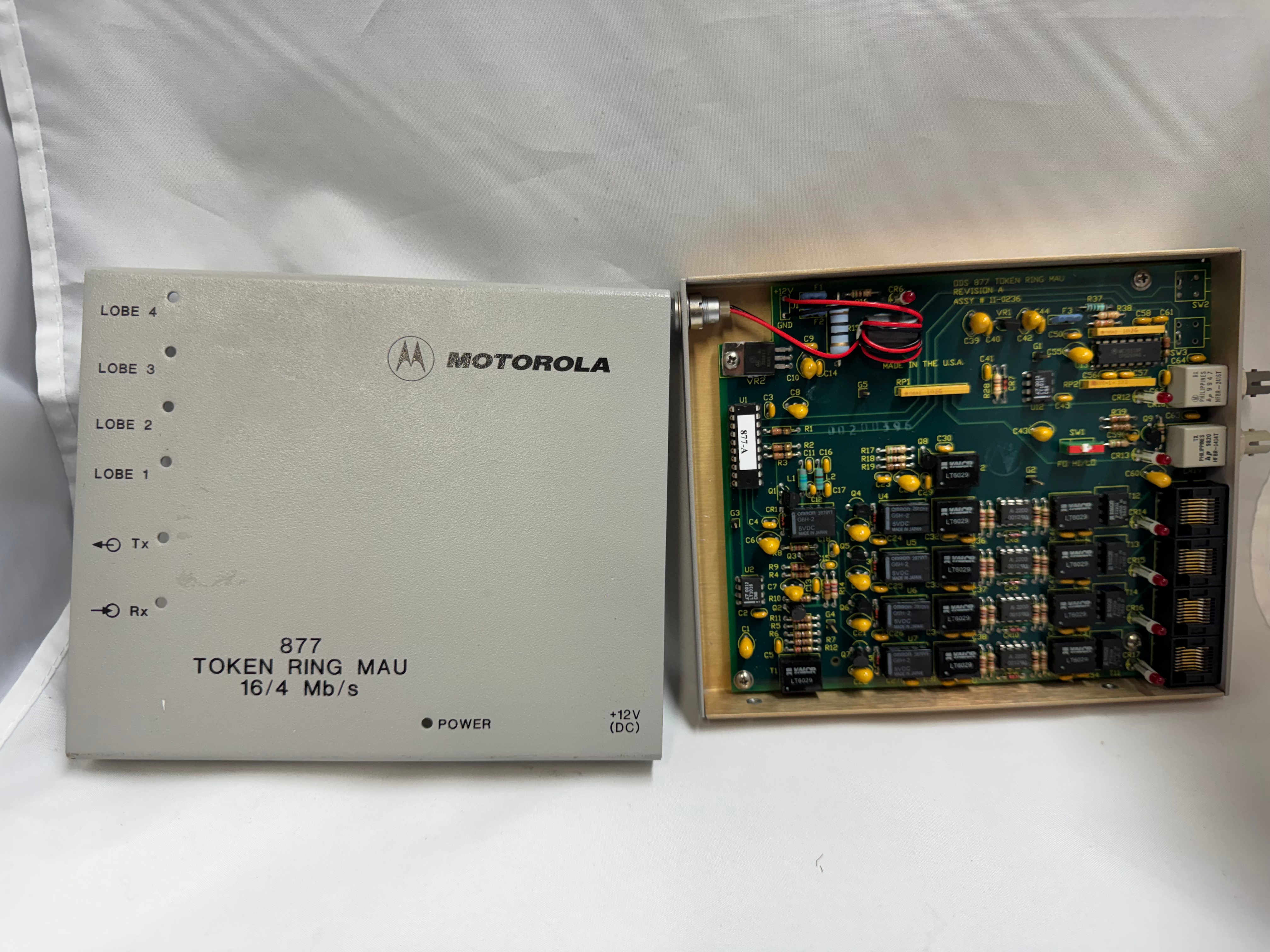
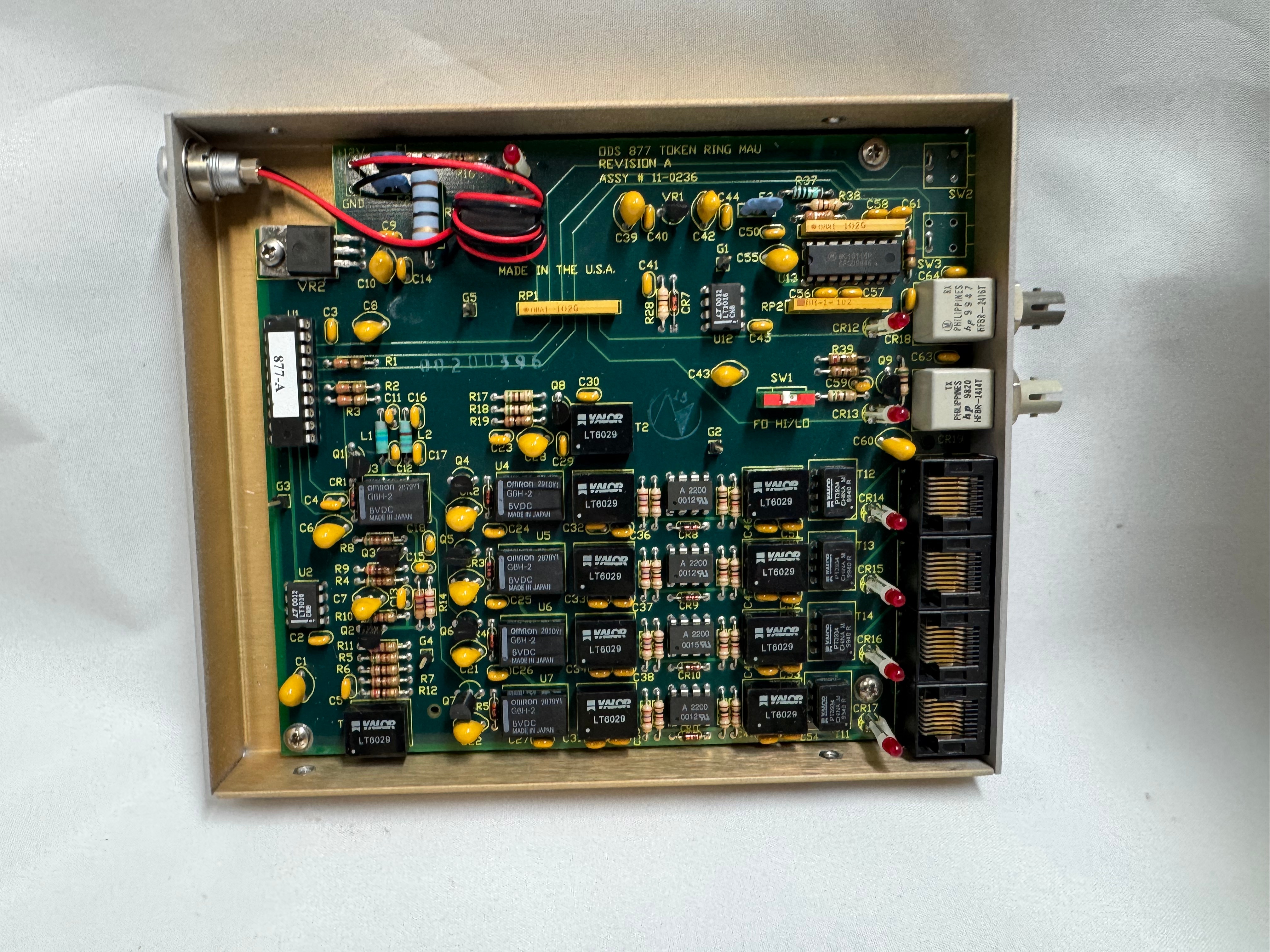
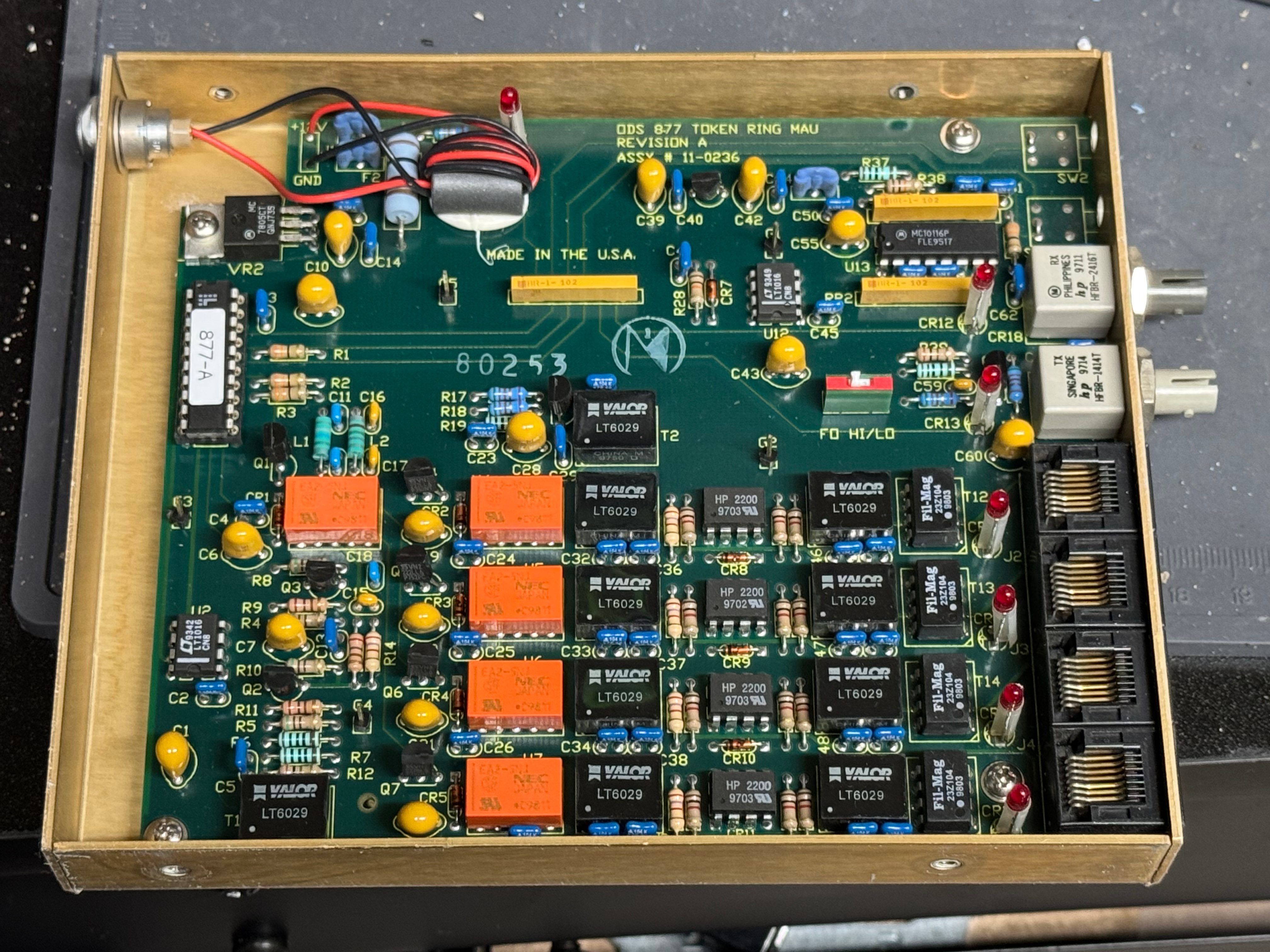
I picked up 2 of the same model MAU. ODS/Motorola 877. These are great units after some hardware tweaks and I would recommend them. While they are the same model, and same firmware revision, Motorola bought the company ODS (Optical Data Systems) which made them. The first one I got has ODS branding and a spot for two switches to control the mode and speed of the MAU. The second one is Motorola branded on the case, but not the board, and is missing the cut out in the case for switches.
From what I can learn with working on it, looking at documentation for other MAUs, and Claude; the device can work in three modes:
- RING: Normal Token Ring operation, requires external RI/RO loopback cable to close the ring, use this when daisy-chaining multiple MAUs together, all active lobe ports are part of the ring.
- STAR: Each port operates independently (not a true ring), used for certain troubleshooting or special configurations.
- LOOP: Internally connects Ring In to Ring Out, self-terminates the ring without external cables, perfect for a single standalone MAU.
The MAUs were designed to have a switch to go between modes. Neither of mine did, both had a physical soldered in jumper setting their mode. The Motorola one didn’t have a hole in the case for a switch to exist, but the PCB is the same. I removed the soldered jumper and replaced it with a standard PC jumper pin, that way I could easily change it when I wanted to. In the end I will leave them both in LOOP mode most of the time, that has internal termination and is used for simple 4 port usage. Bridging the top and middle pin put it into LOOP mode, which is what I needed. Before that it was in RING without termination; each device would join the ring for 10 or so seconds, not hear anything else on the ring, and then disconnect. This MAU appears to be able to automatically go between 4mb/s and 16mb/s mode and I never moved the speed jumper.
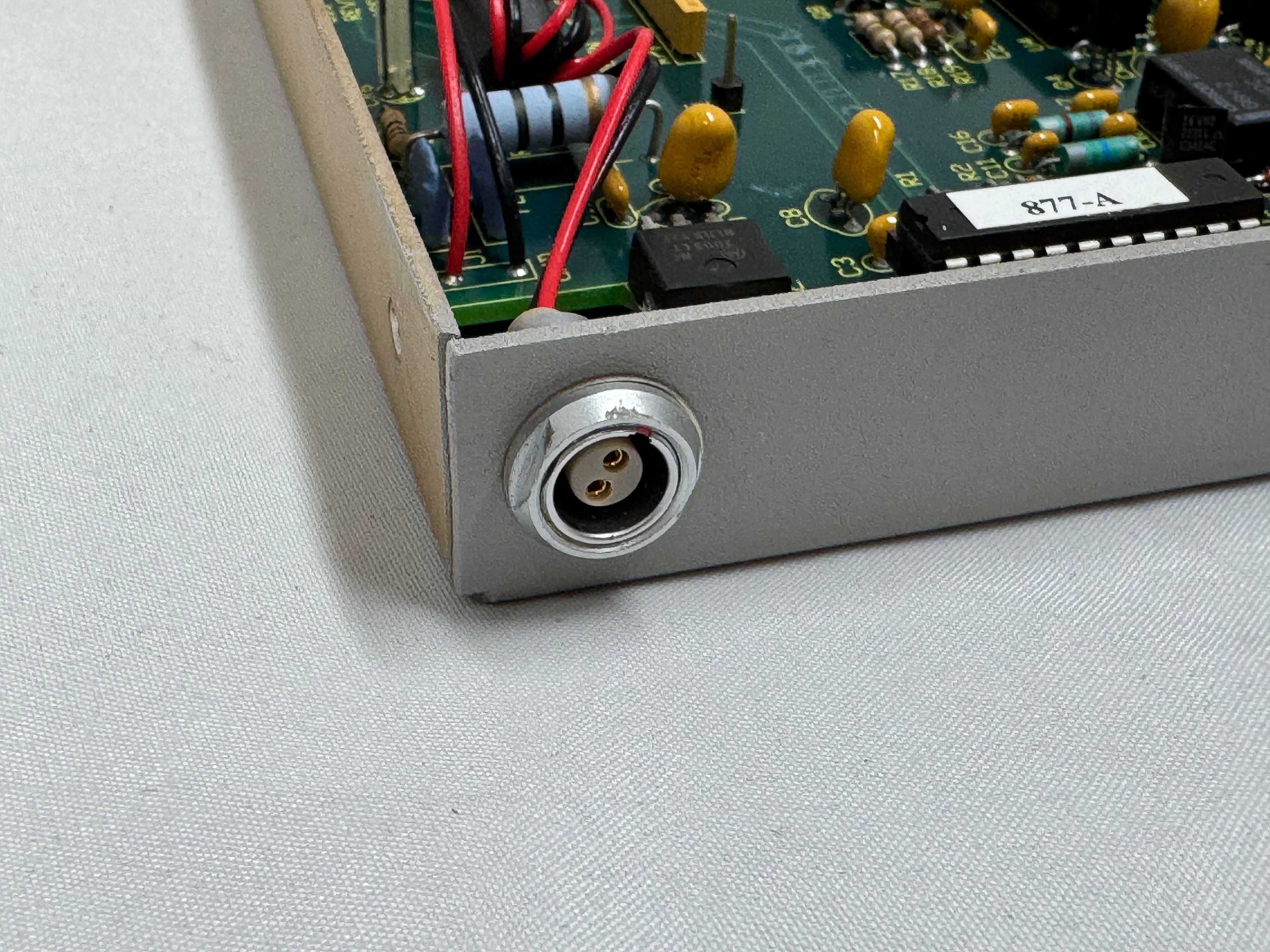
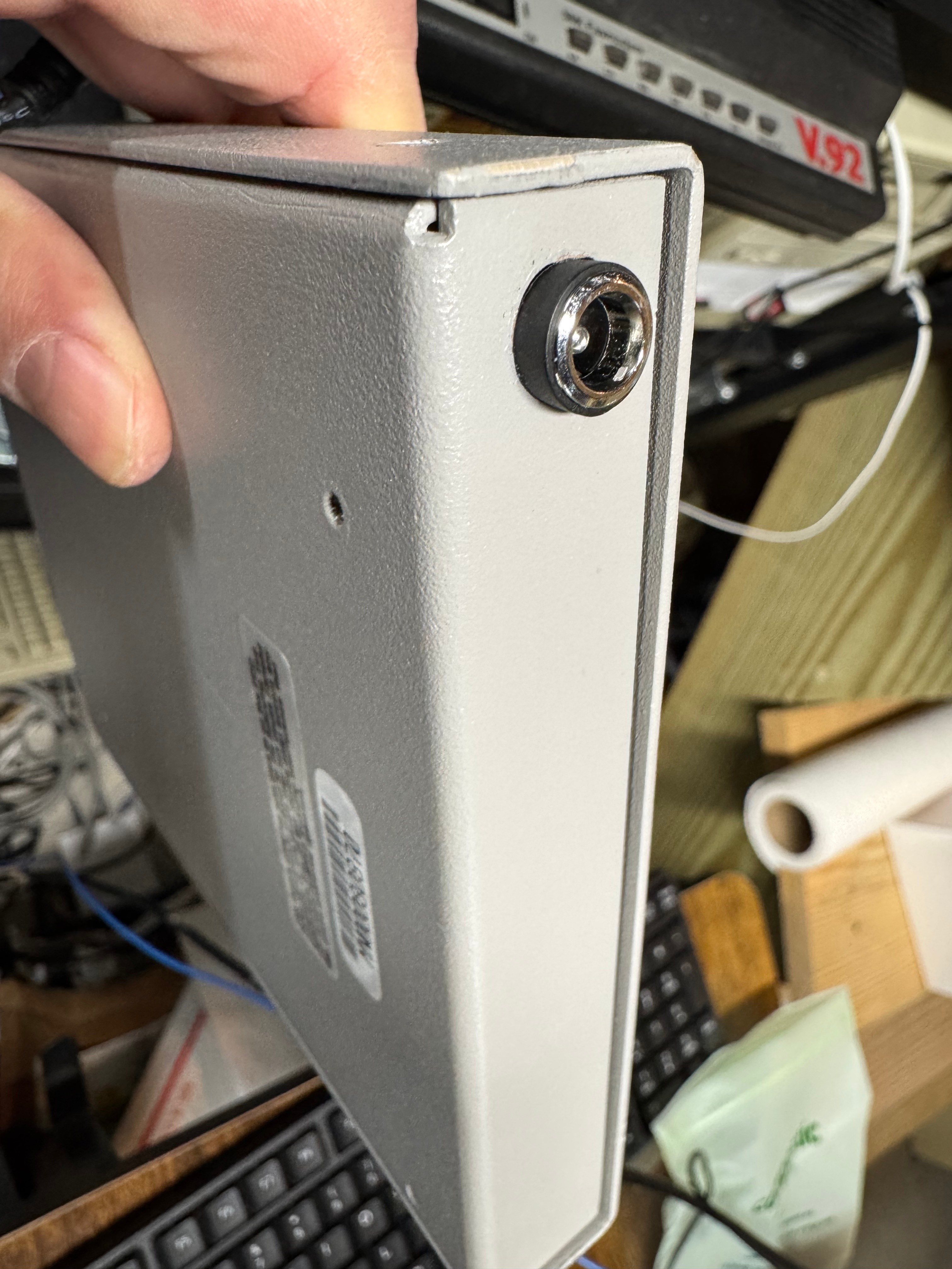
The two modifications I made to these devices were the mentioned jumper change; and they come with a FGG 2P power connector onto a RJ45 plug. It says it needs 12V on it, and I wanted to just be able to use a wall plug, I first tried to get that connector, but after finding it tiny and hard to work with, I replaced the port in the device with a standard barrel plug.
Token Ring Drivers
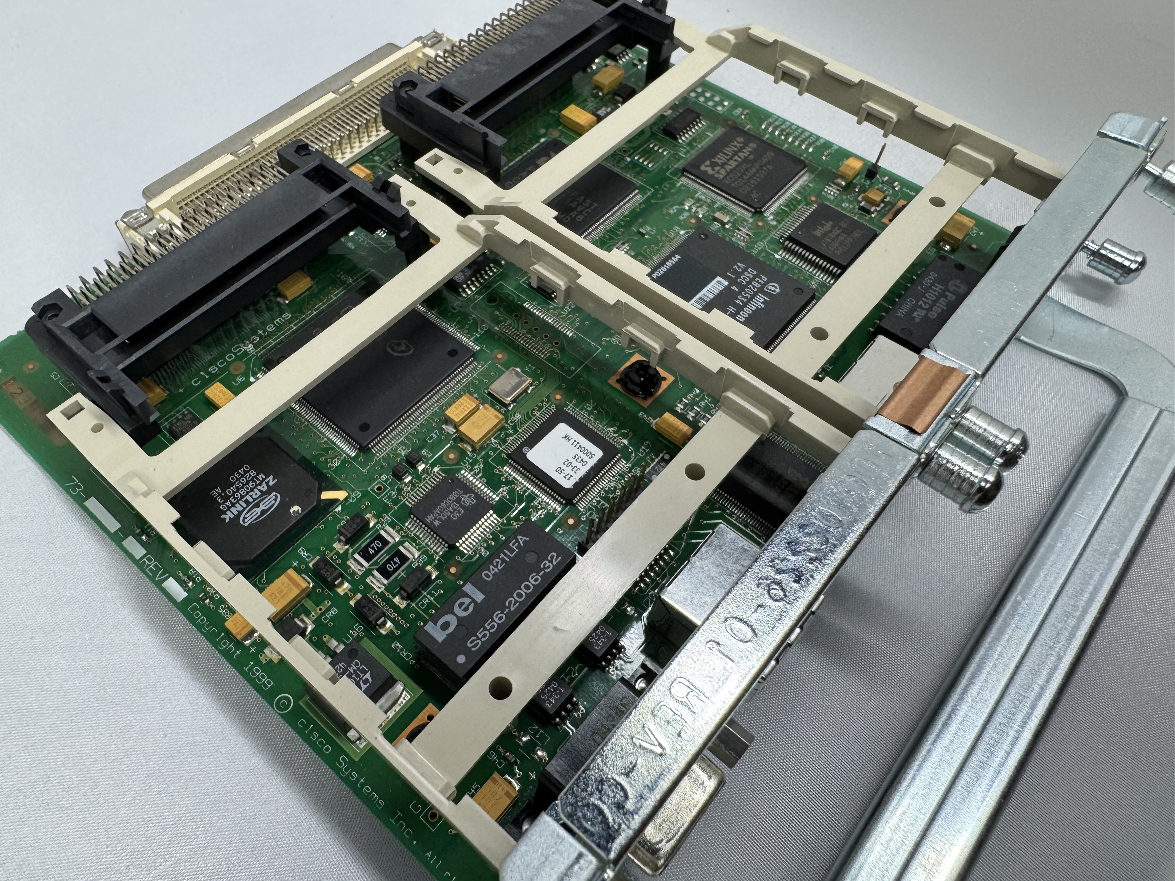
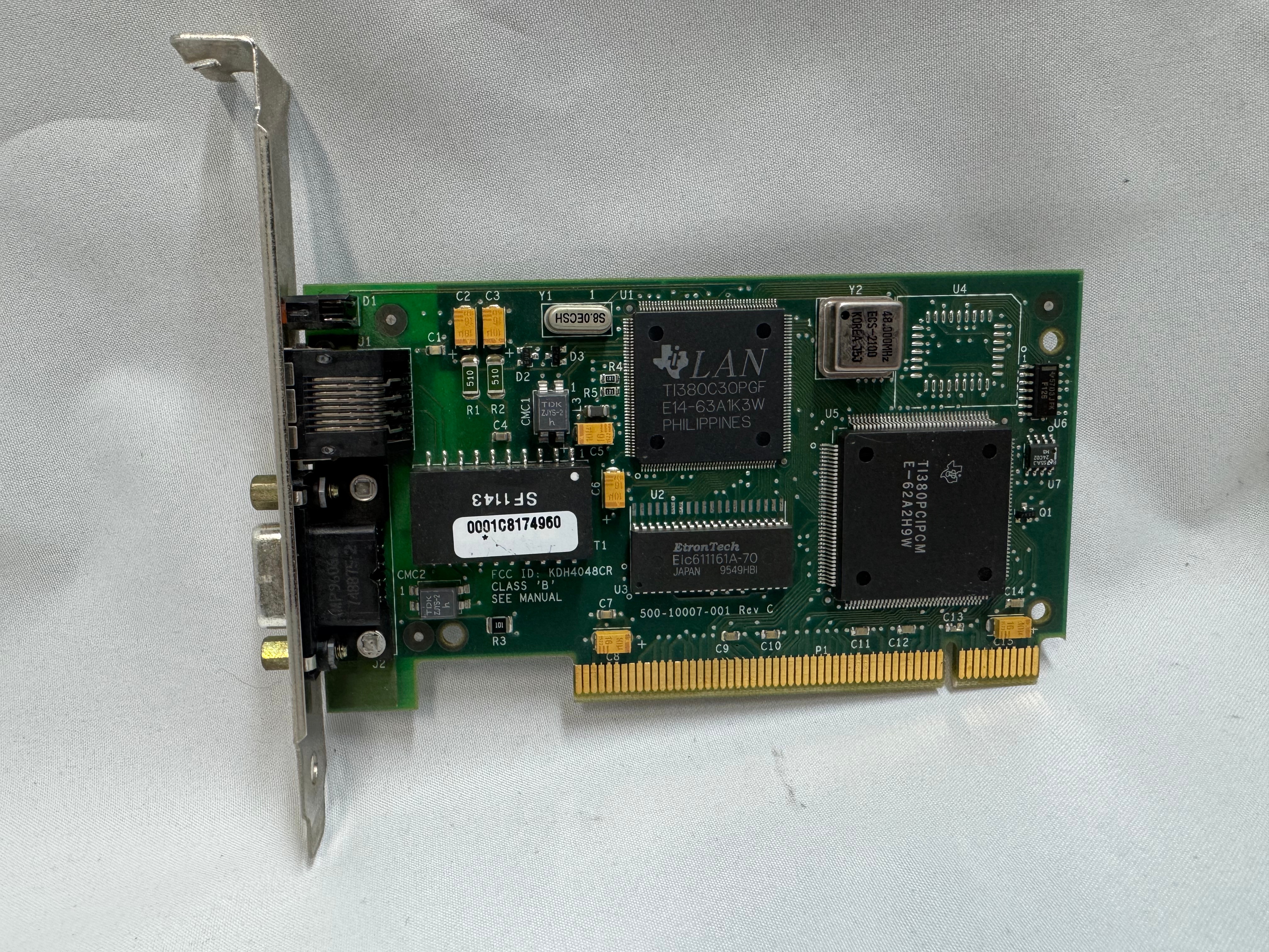
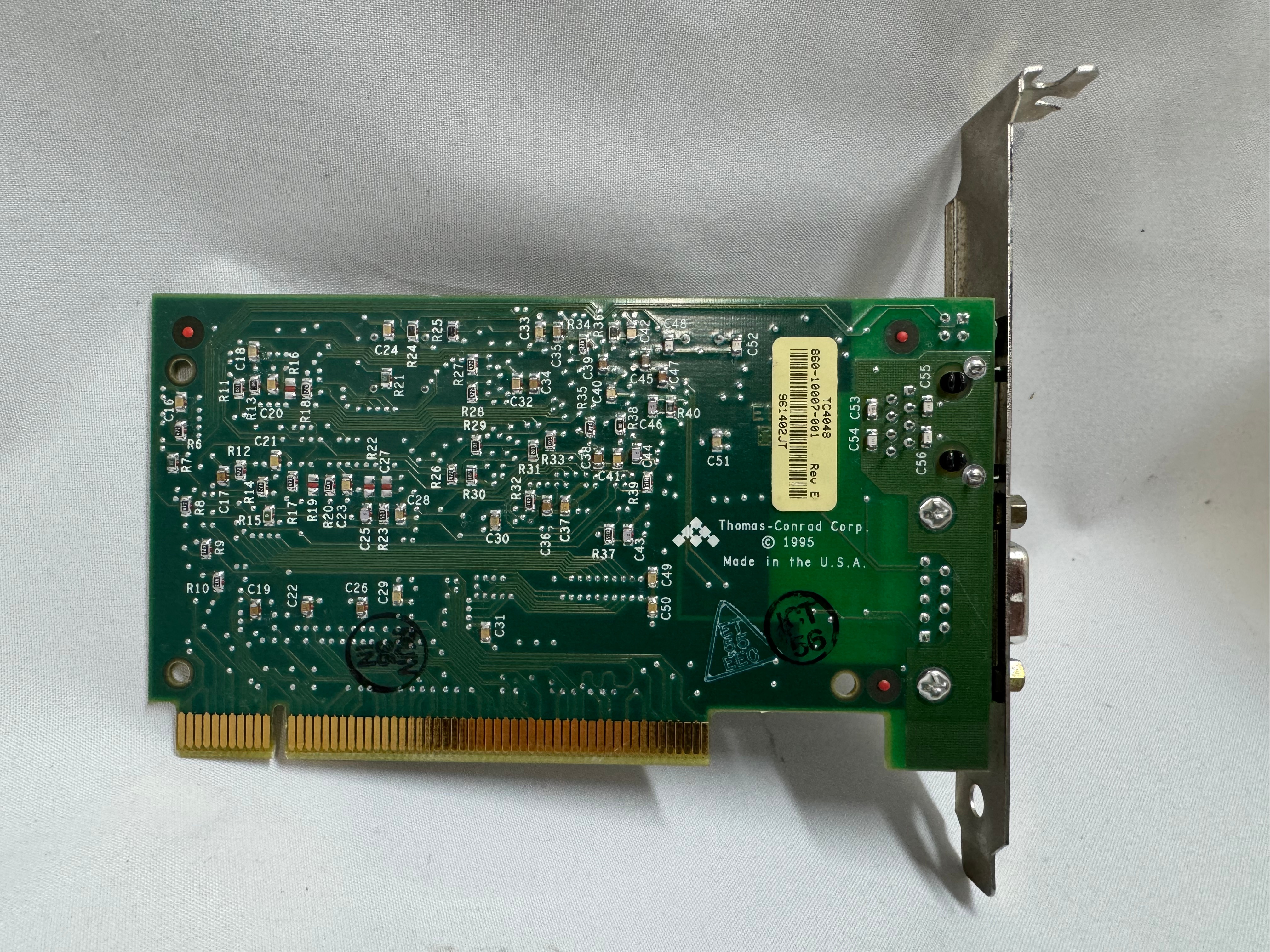
One difficult part of finding Token Ring cards on eBay, you never know if you can find all the drivers. The card I have is a later model PCI card. It’s a Thomas Conrad TC4048. Thomas Conrad seems to have been an interesting company putting out different network cards over the 80s and 90s before ethernet took off. It is easy to find their Token Ring and Arcnet cards online. Finding their drivers on the other hand, proved to be difficult.
Driver Hunting
I found https://archive.org/details/pwork-297 this archive.org ISO, it contains a TON of drivers for devices in the 90s. It lists TC4048 as one of them. I download the image, install the driver AND… Windows 98 says it has the tc4048 files it needs except a “tc4048.dos”. I then found https://www.minuszerodegrees.net/software/Compaq/allfiles.txt this site which has every HP/Compaq driver that used to be on their site. Those are much easier to search. There were several TC4048 items.
I found an archive at https://ftp.zx.net.nz/pub/archive/ftp.compaq.com/pub/softpaq/sp19501-20000/, and downloaded sp19859.exe, which expanded and had “DOSNDIS” and “OS2NDIS”. I knew Compaq rebranded this card, so I yoloed and renamed “DOSNDIS/CPQTRND.DOS” to “tc4048.dos” and put it with the drivers I got from the archive.org image. The Thomas Conrad drivers from different vendors had similar files with different names, but they were the exact same size, and appeared to be the same… I hoped it would just work if I renamed a file from a different vendor to the one I needed. I made progress with error messages now seeing “svrapi.dll” missing in C:\Windows\, and found that file in C:\Windows\System32… and just copied it up one directory…
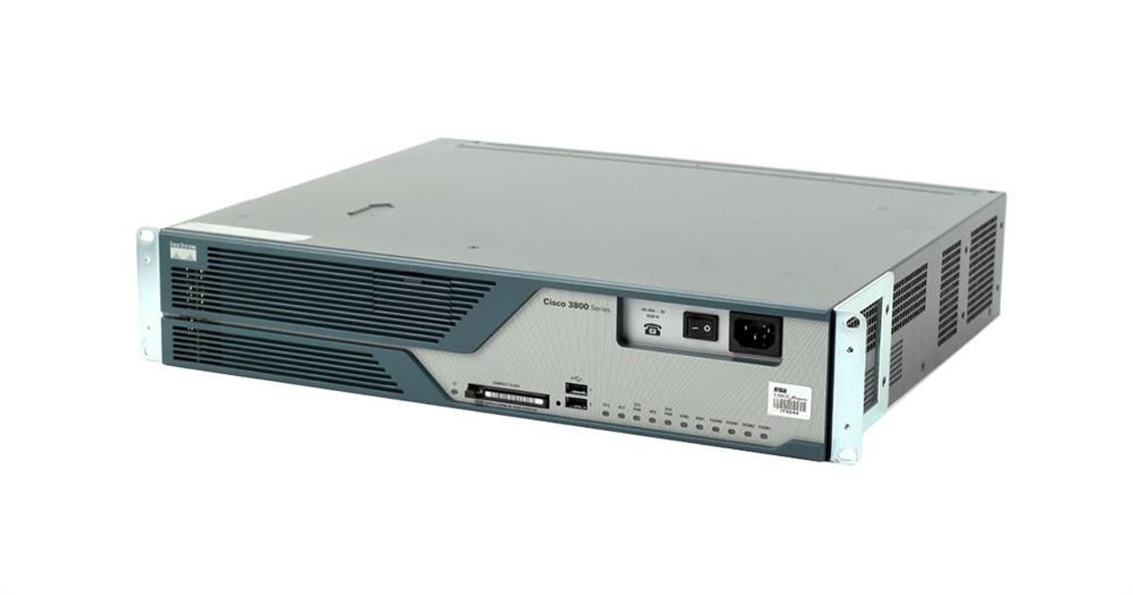
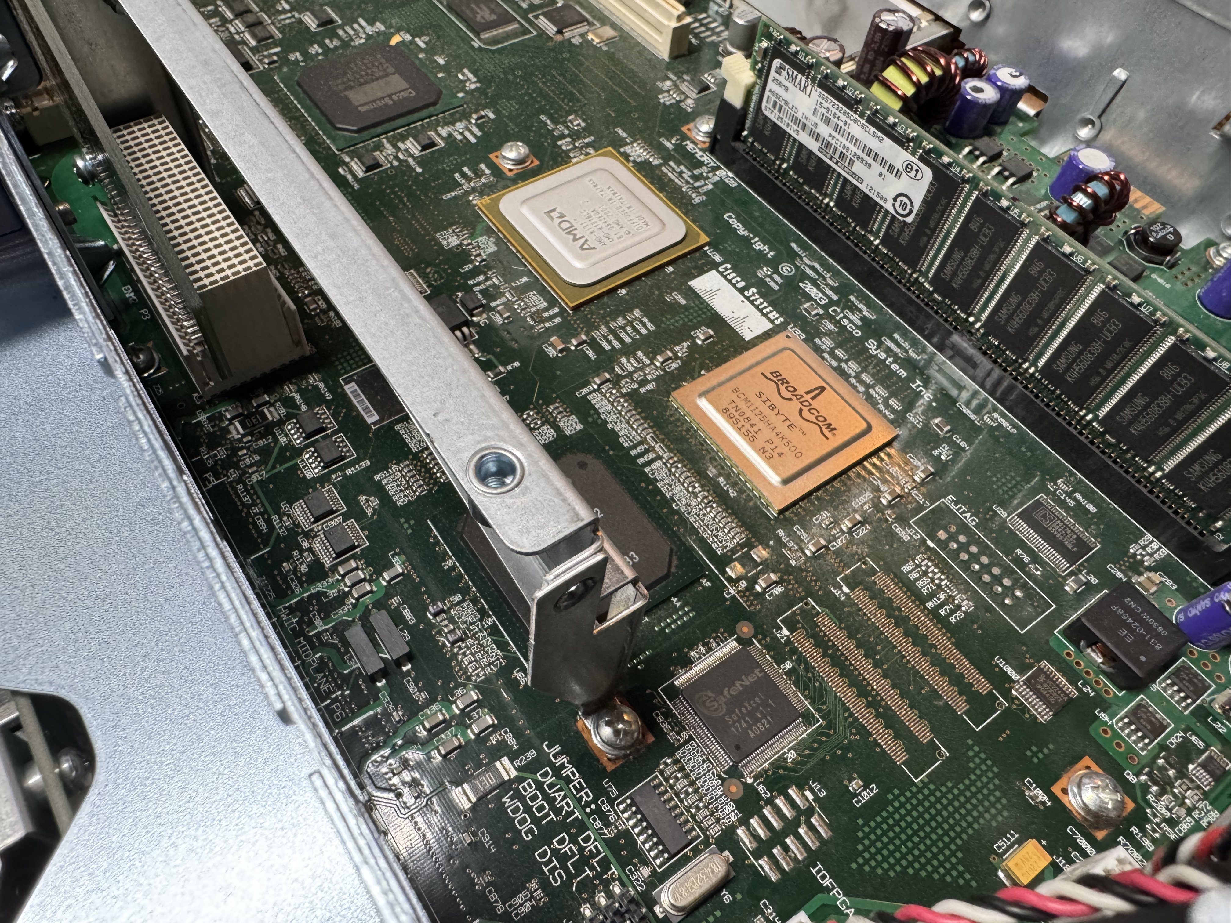
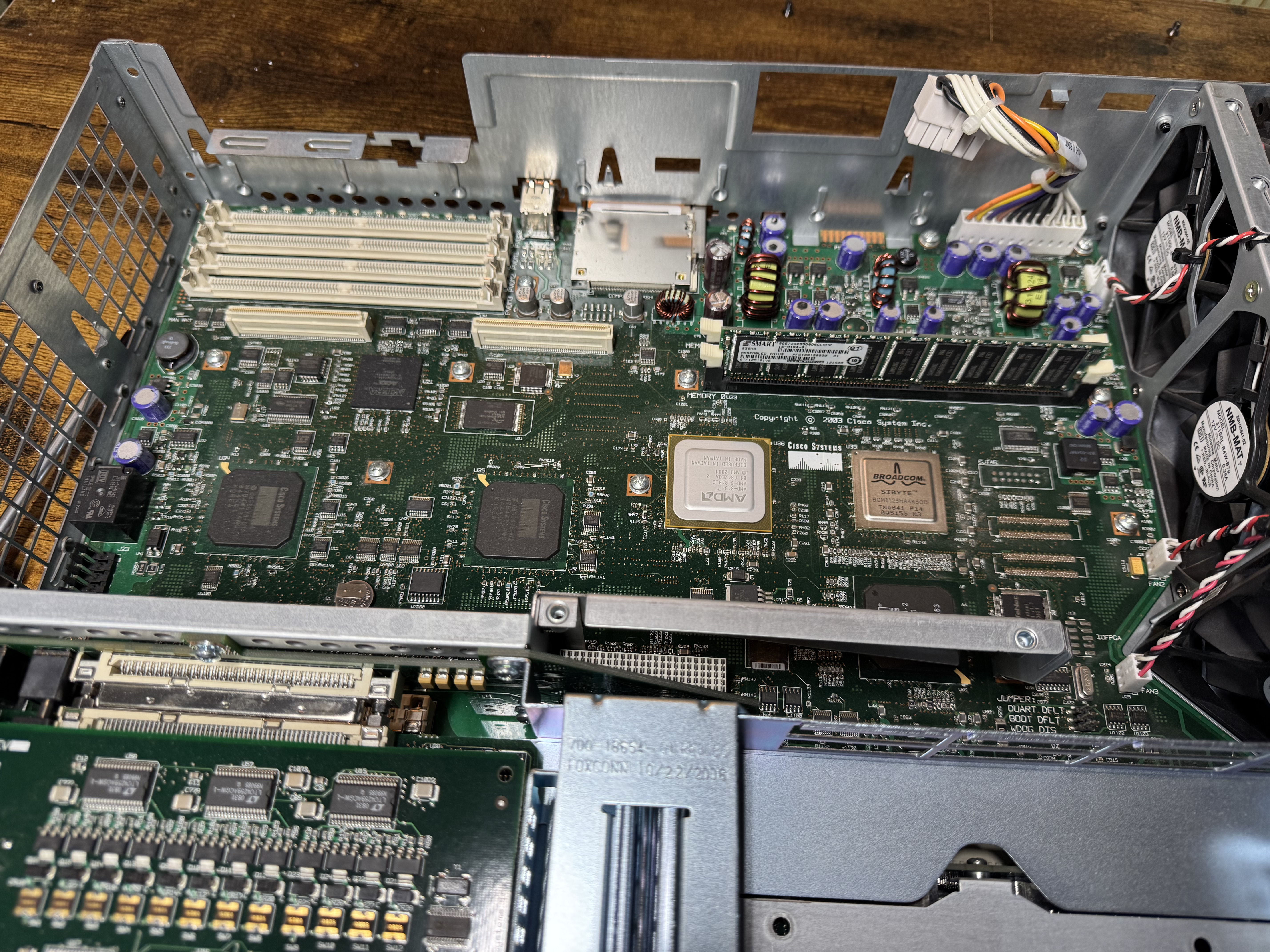
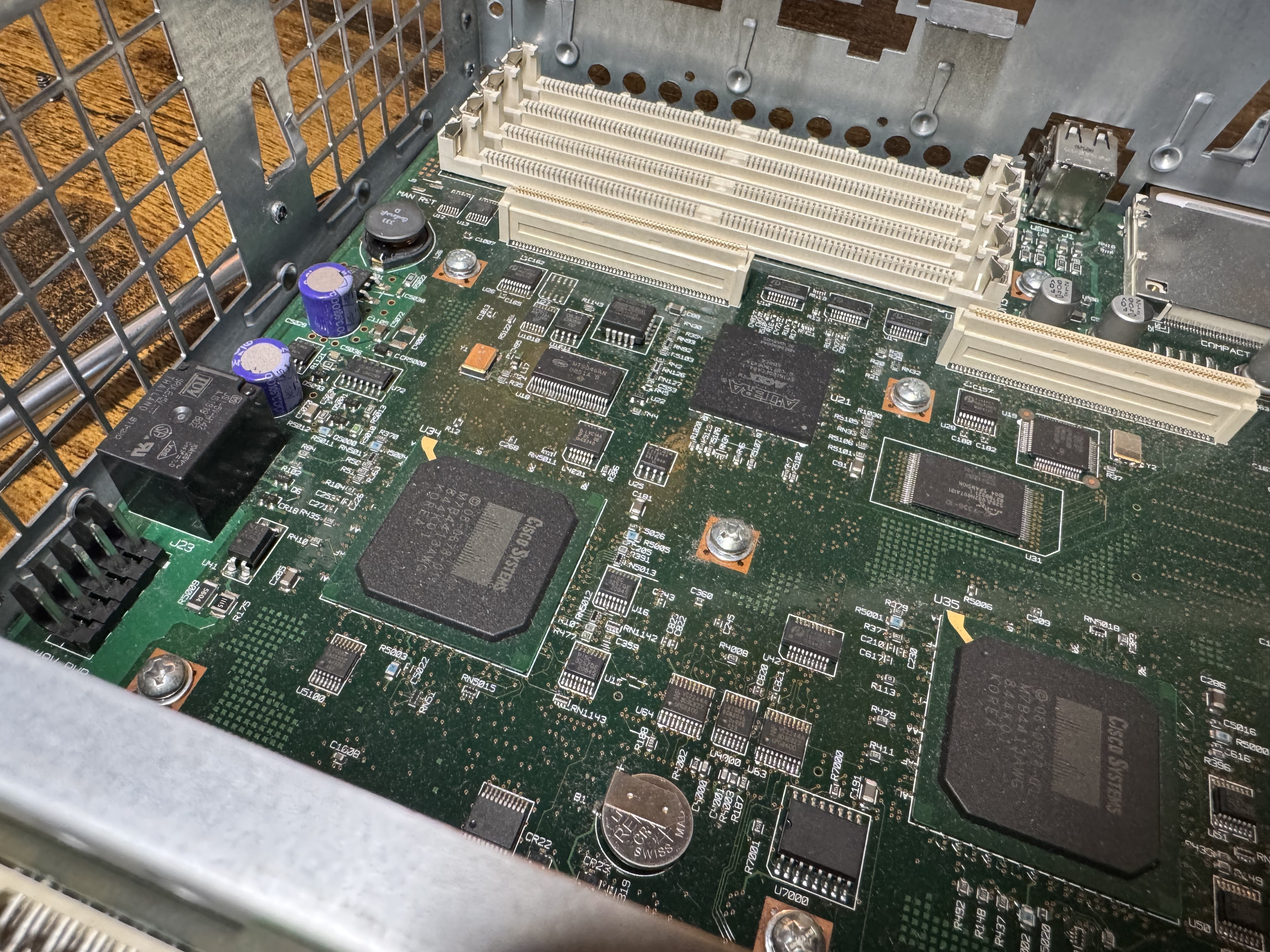
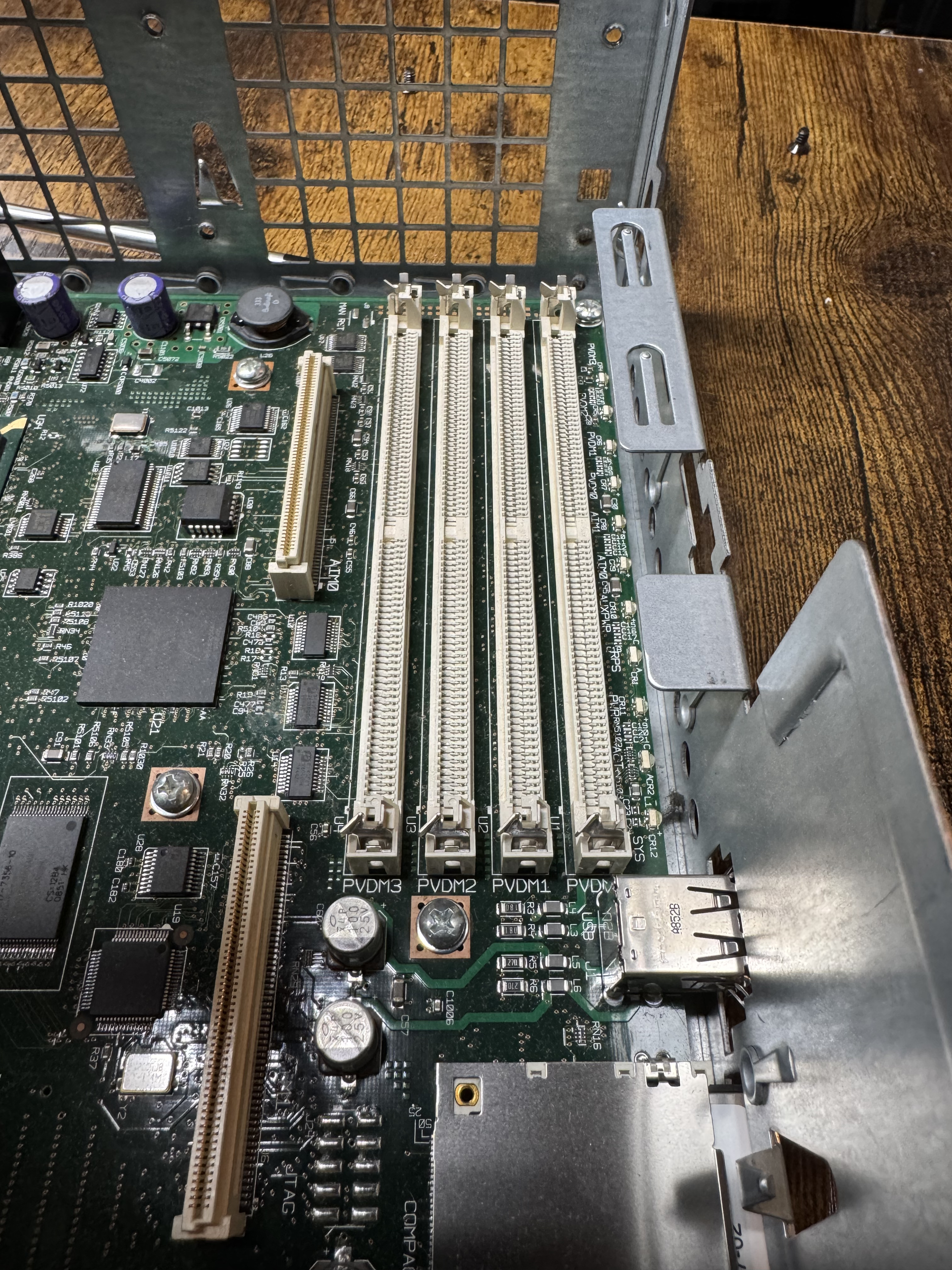
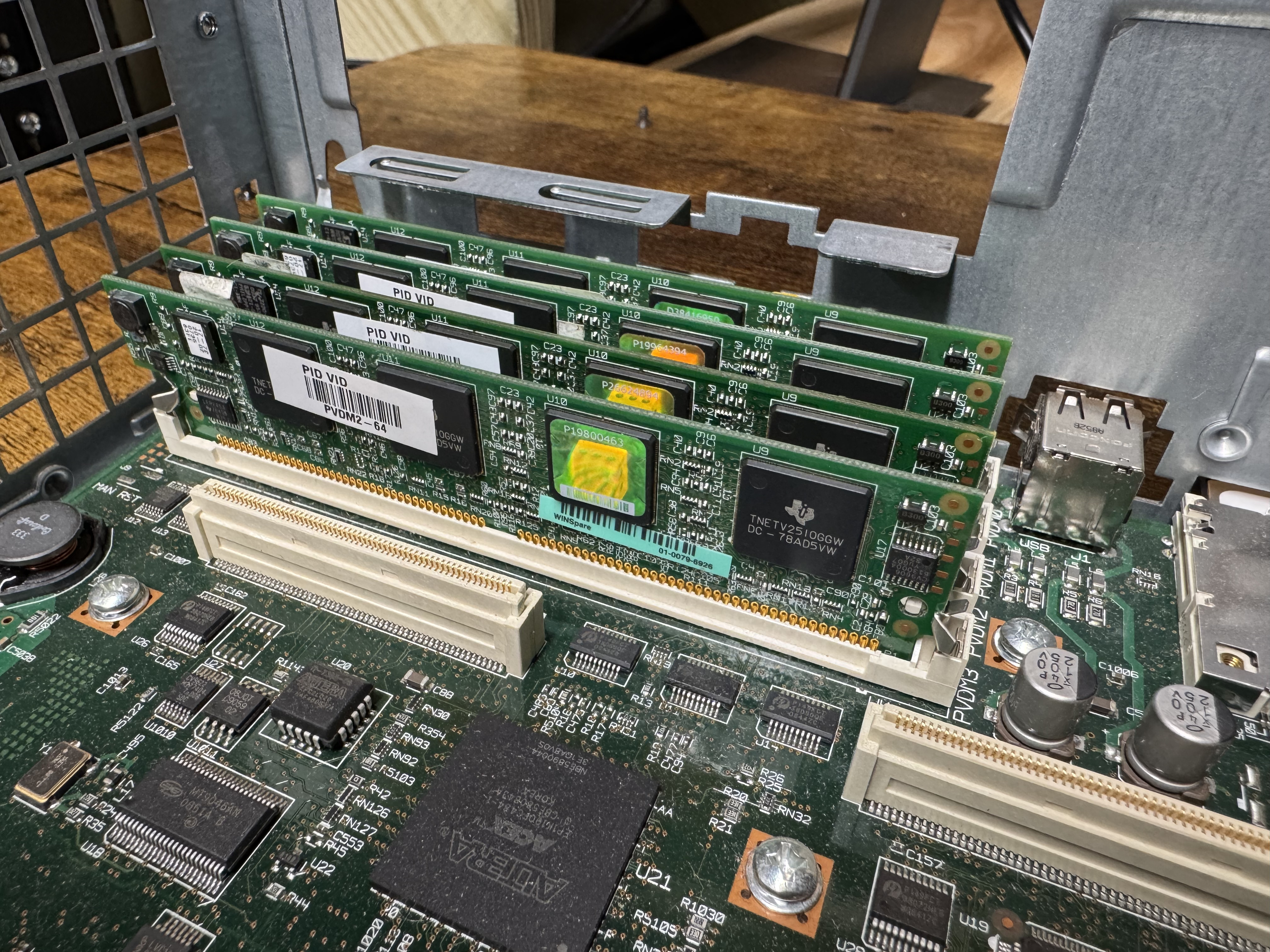
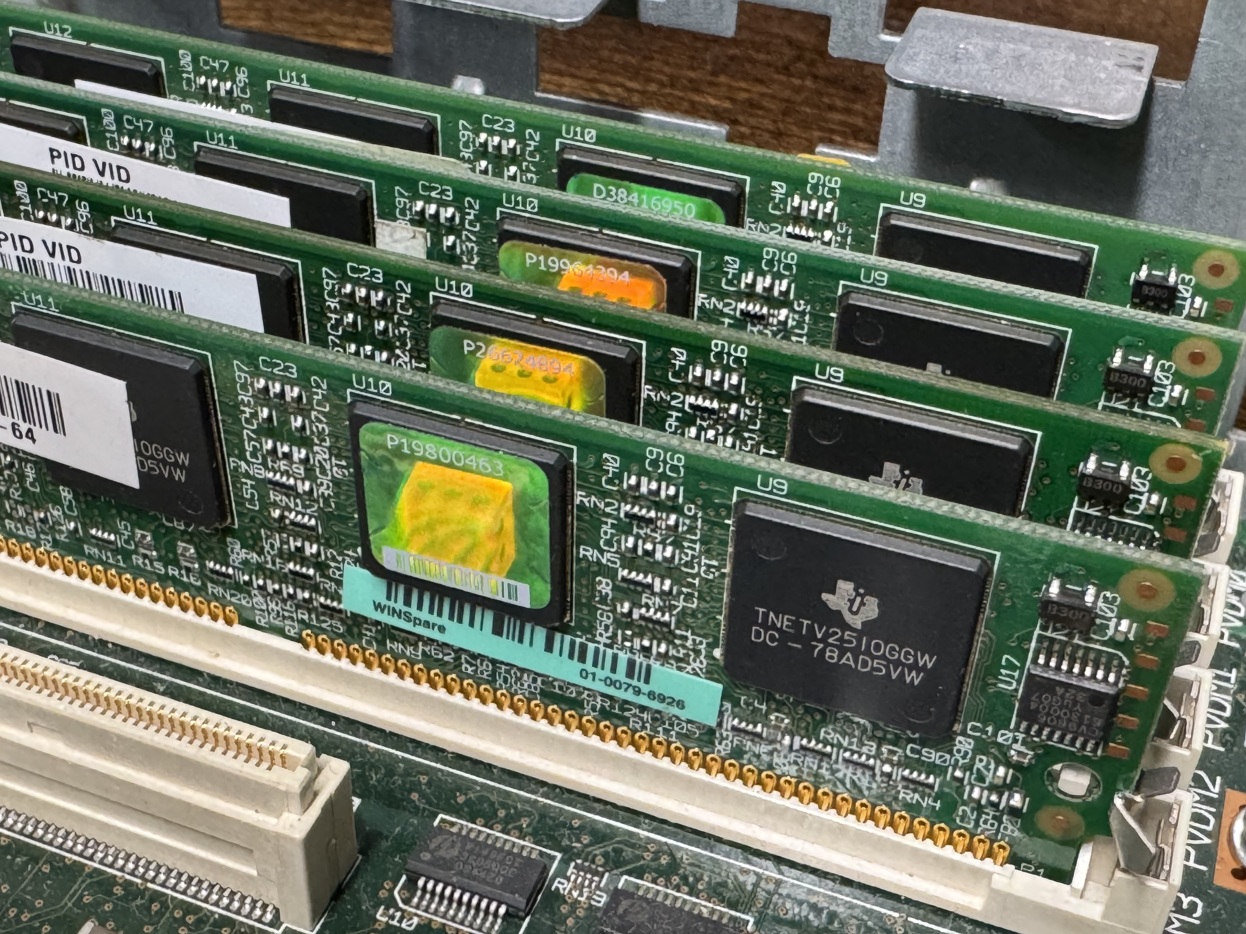
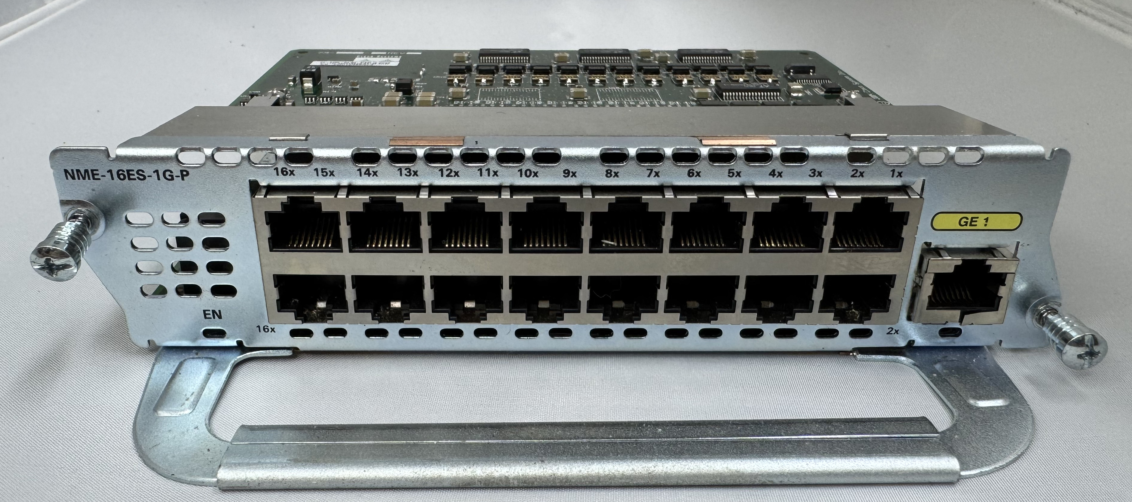
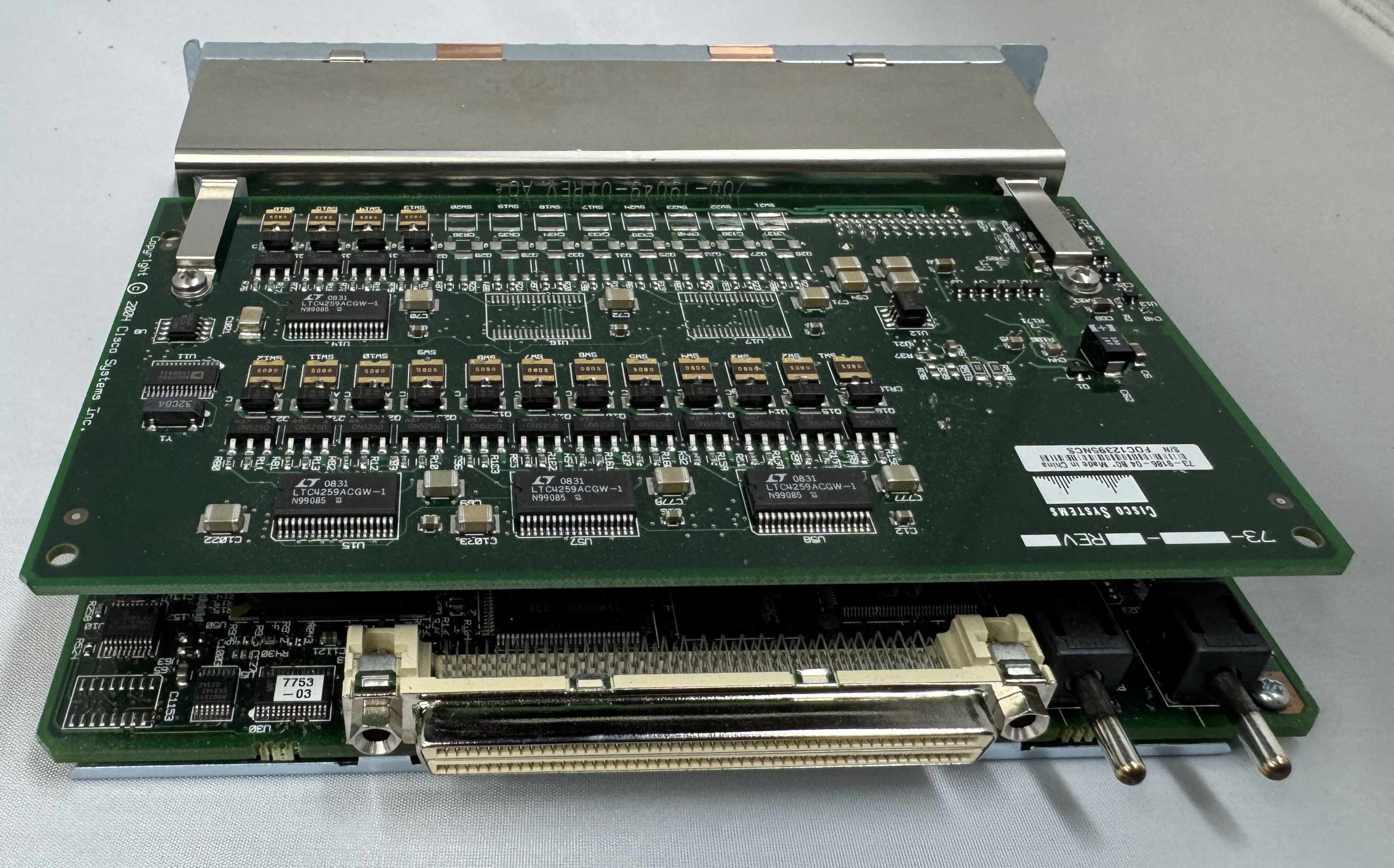
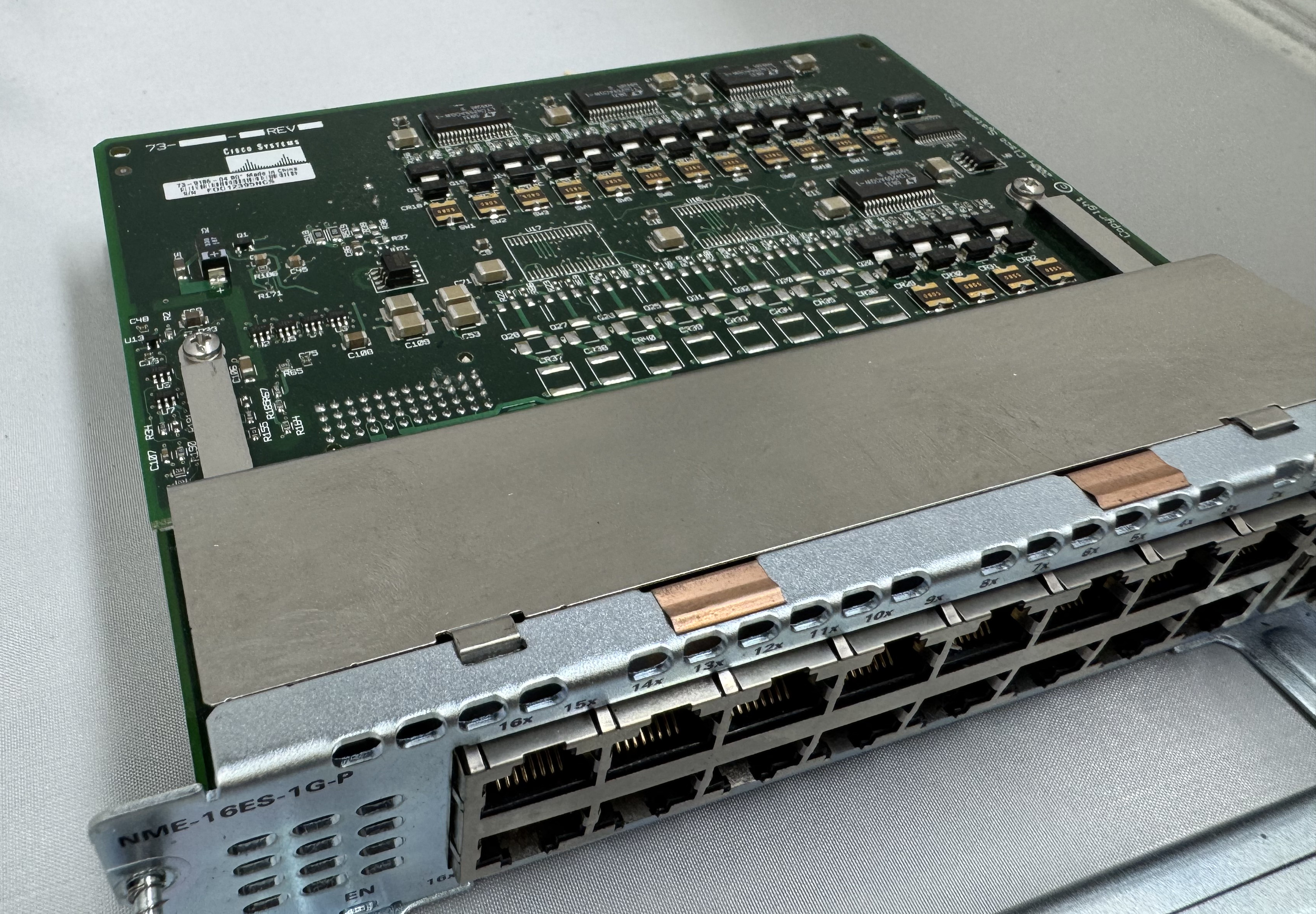
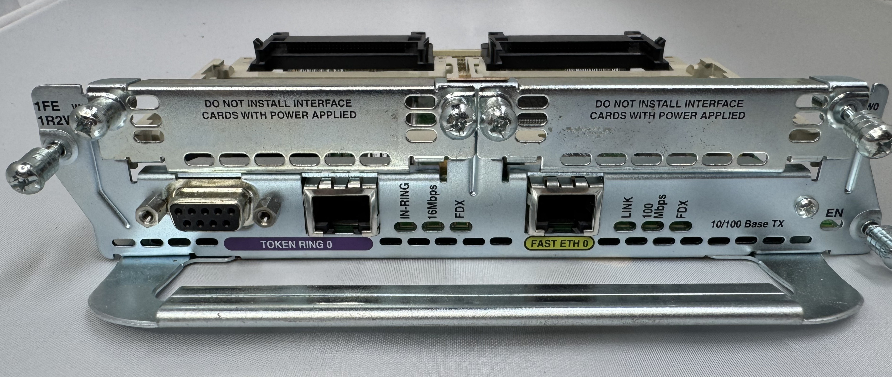
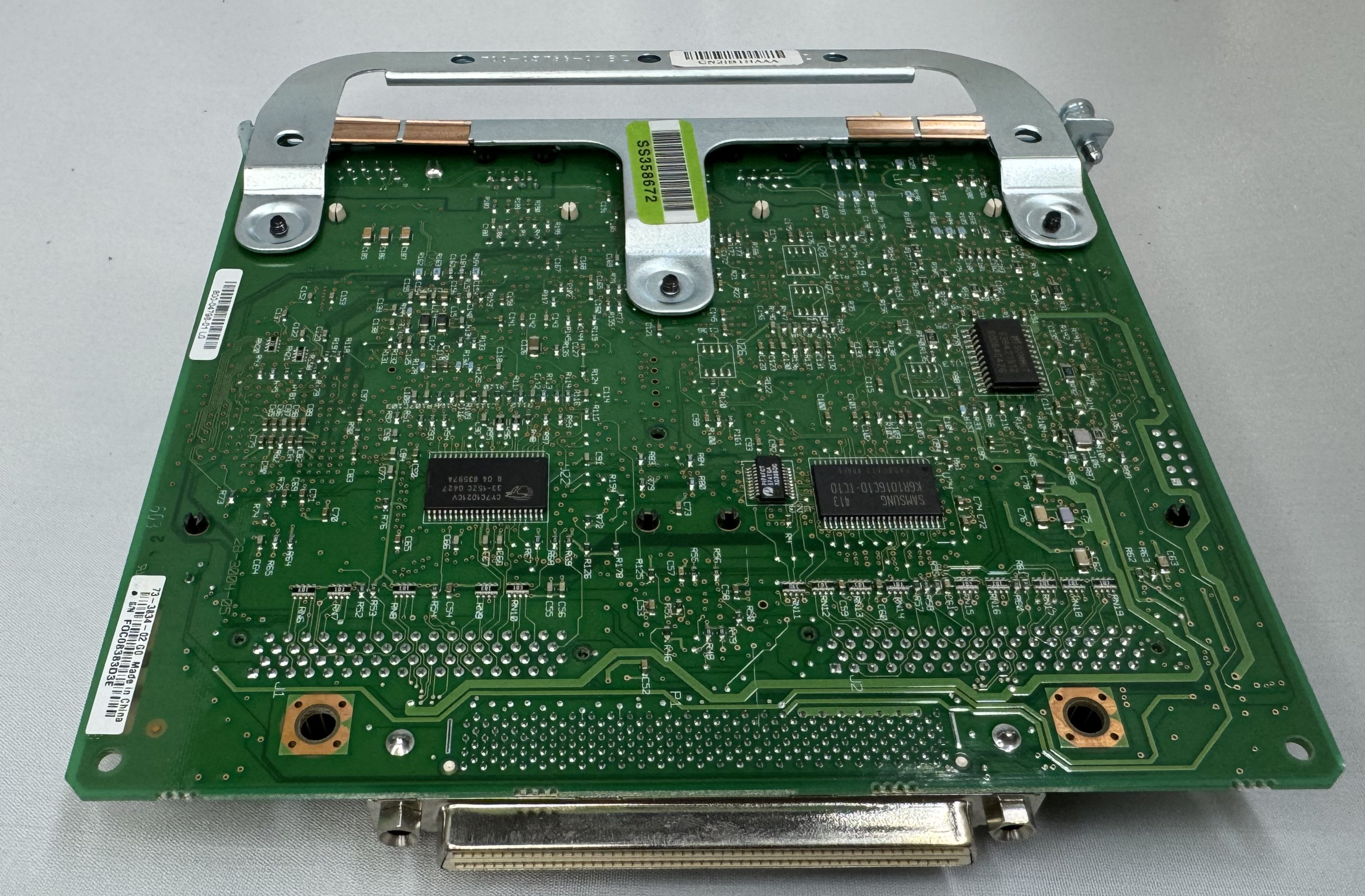
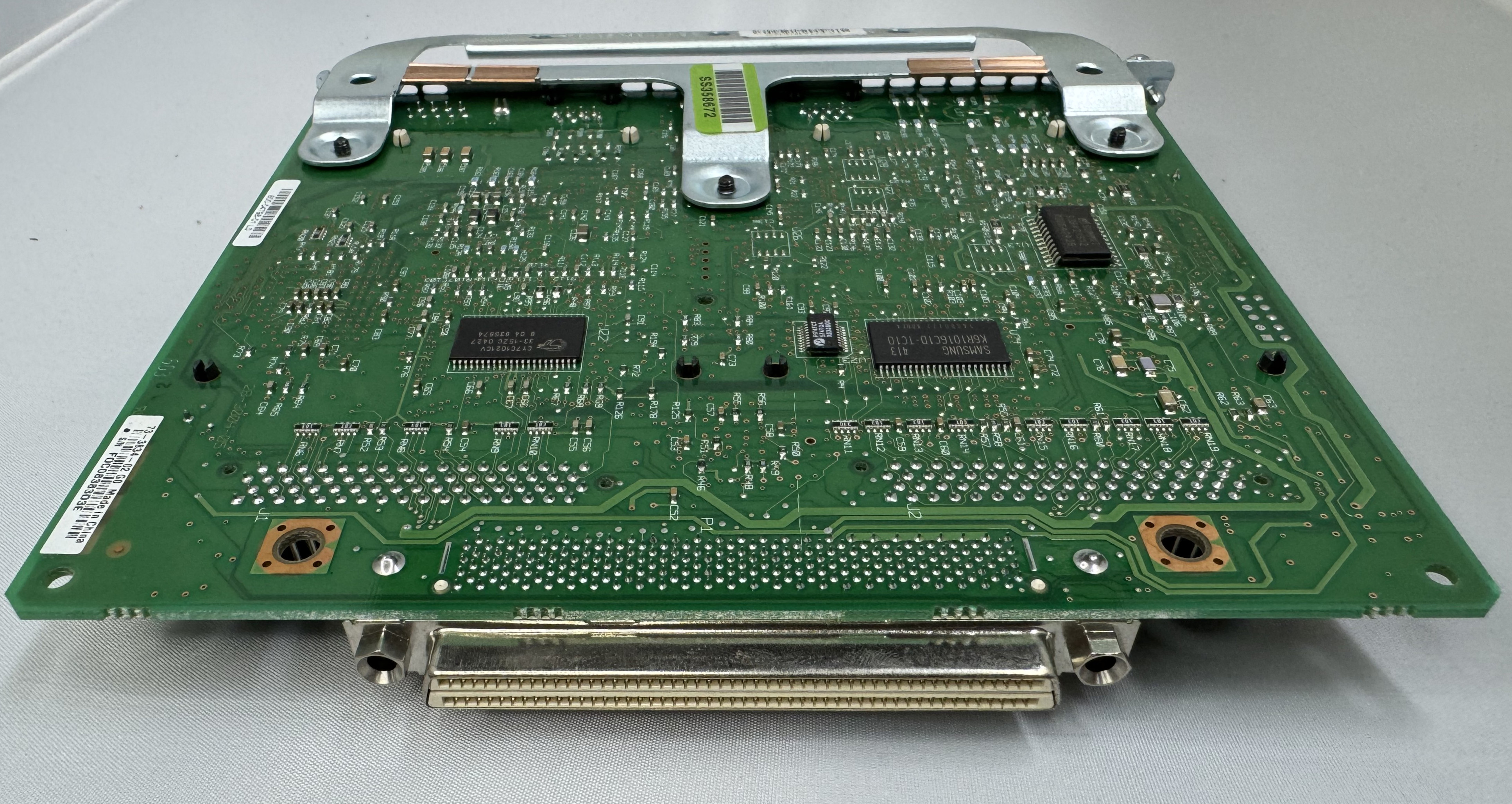
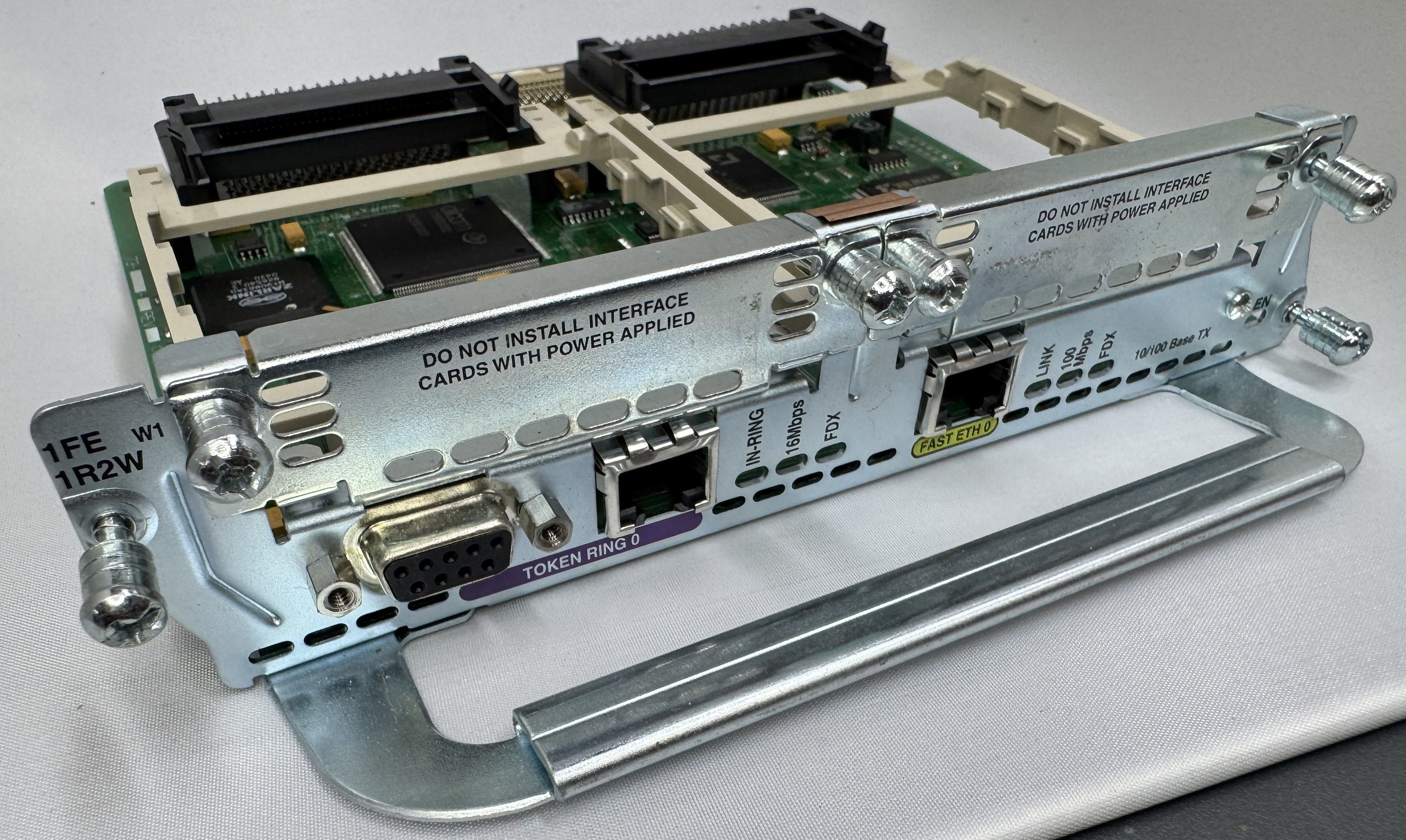
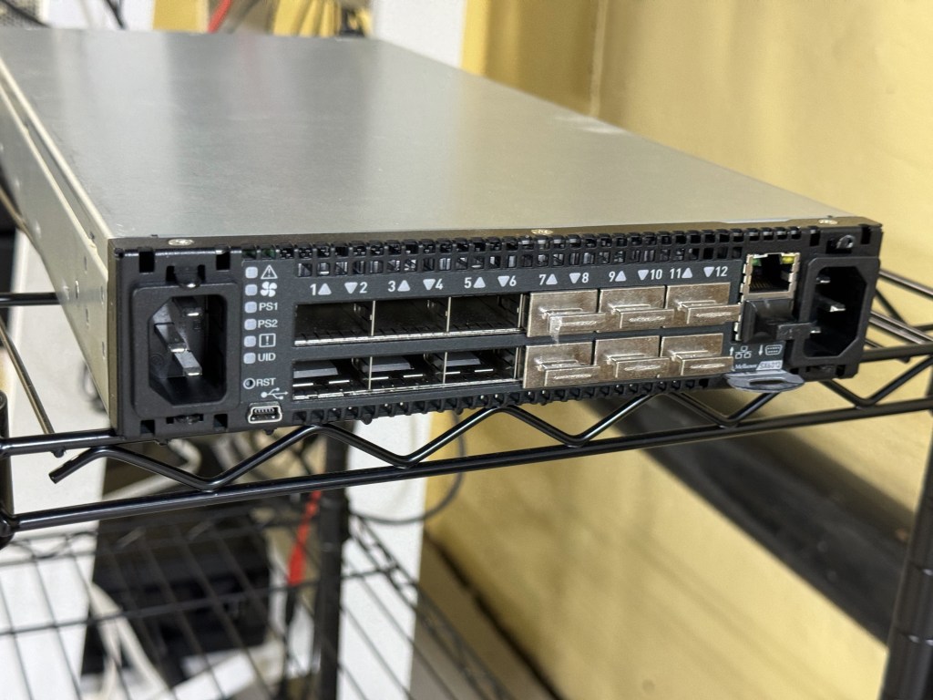
And magically that worked! I had a 16mb/s connection working between the Cisco 3825 (core) and the Windows 98 PC (edge)! The core of my retro network is a Cisco router. I purchased this Cisco 3825 system a while back because it’s the last one that supports Token Ring, but new enough to have 1gb/s uplink port to my core network. This allows me to host some retro VLANs internally, and firewall them off for security (since none of these systems have gotten patches for decades). I can play with Novell Netware and host a file share of games for the retro systems on this network as well. Using even legacy networks to move files is still a lot easier than a ton of floppy disks. I leave this router off most of the time because it’s a bit power hungry and loud. I have written about it before, and it also hosts my dial up connections.
I now had the Cisco 3825 with a Token Ring card and Windows 98 PC joining a Ring and communicating! I have watched a bunch of clabretro’s videos on Token Ring, and I saw the same issue with the Thomas Conrad drivers that he saw with his cards, Windows joining a Token Ring network and the drivers have an odd interaction. When the computer boots, at that point it tries to join the ring, the system will stay at the Windows startup screen an extra-long amount of time as it tries to enter the ring. The system will also wait at shutdown as it attempts to leave the ring. If the Token Ring card is not plugged in, you get a message about failing to connect after a prolonged startup.
Future Token Ring Plans
I plan to play with Token Ring a bit more both as a standard networking technology alongside the Ethernet network I have. Now that I have two working MAUs I want to experiment with linking them over the ST fiber connectors they have and getting a Token Ring connection over fiber. I am pondering learning FPGAs by building a Token Ring to Ethernet bridge using an FPGA connected to an ISA Token Ring card. I just find it interesting and it would push my FPGA skills; the project would need to translate the headers of Token Ring at layer 2 to Ethernet headers.
Token Ring is the layer 1 and layer 2 technology, after that we use standard TCP/IP on top of it; this has made it easy to get started with Token Ring over another protocol like AppleTalk or IPX. Once the physical connection was up, and devices could enter the ring; I was able to use standard Cisco commands and create a routable DHCP pool for Token Ring.