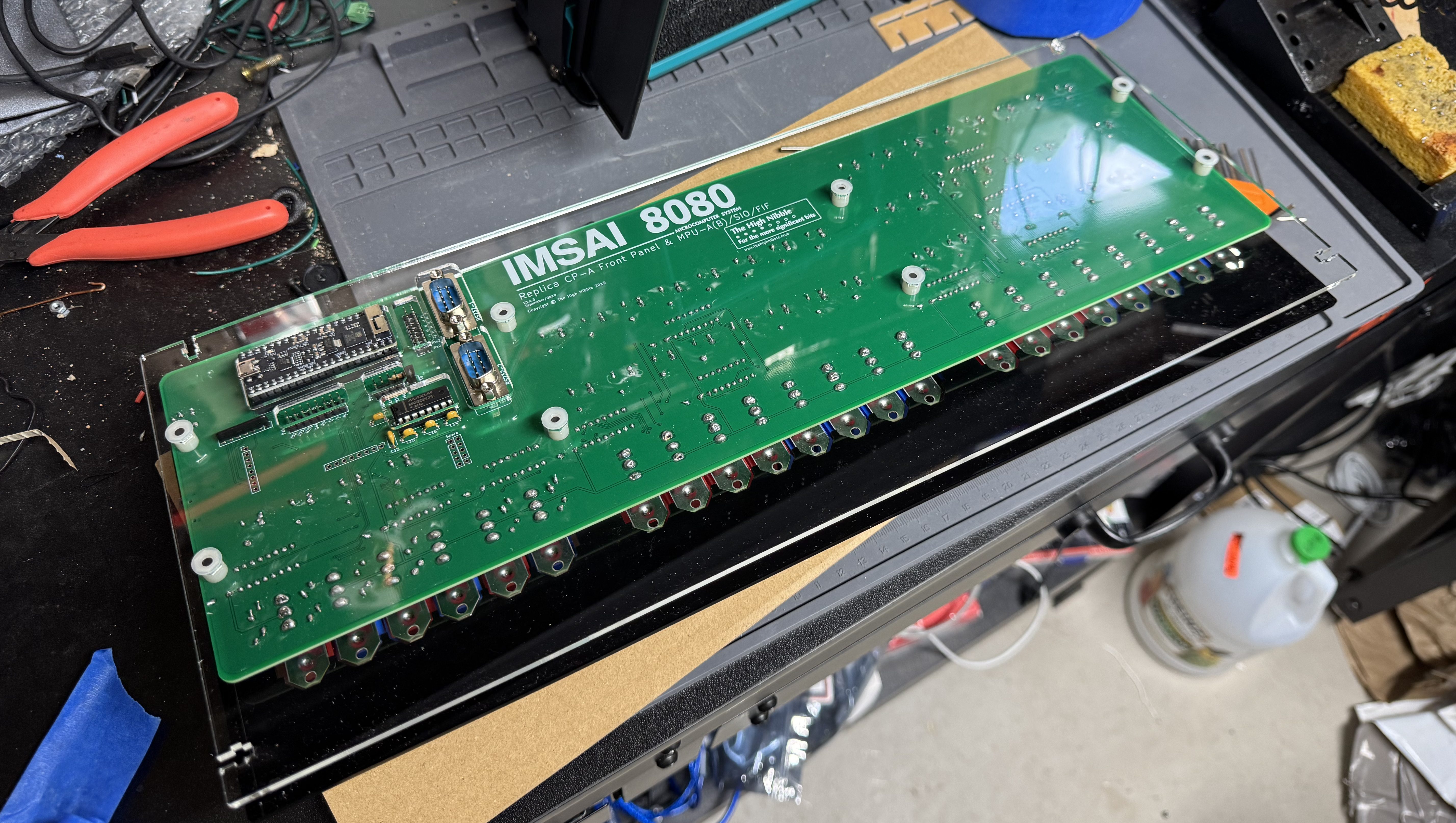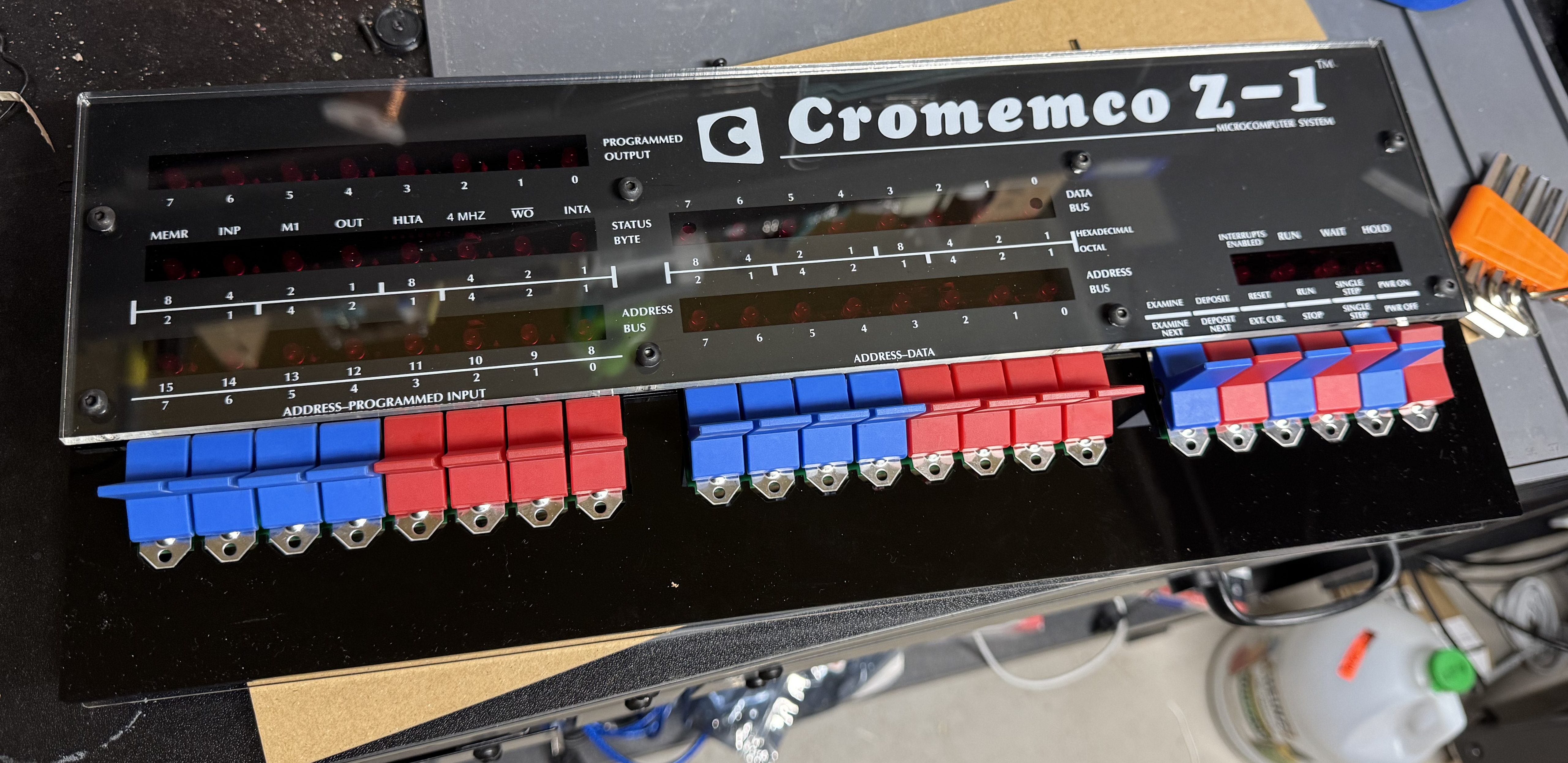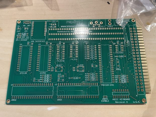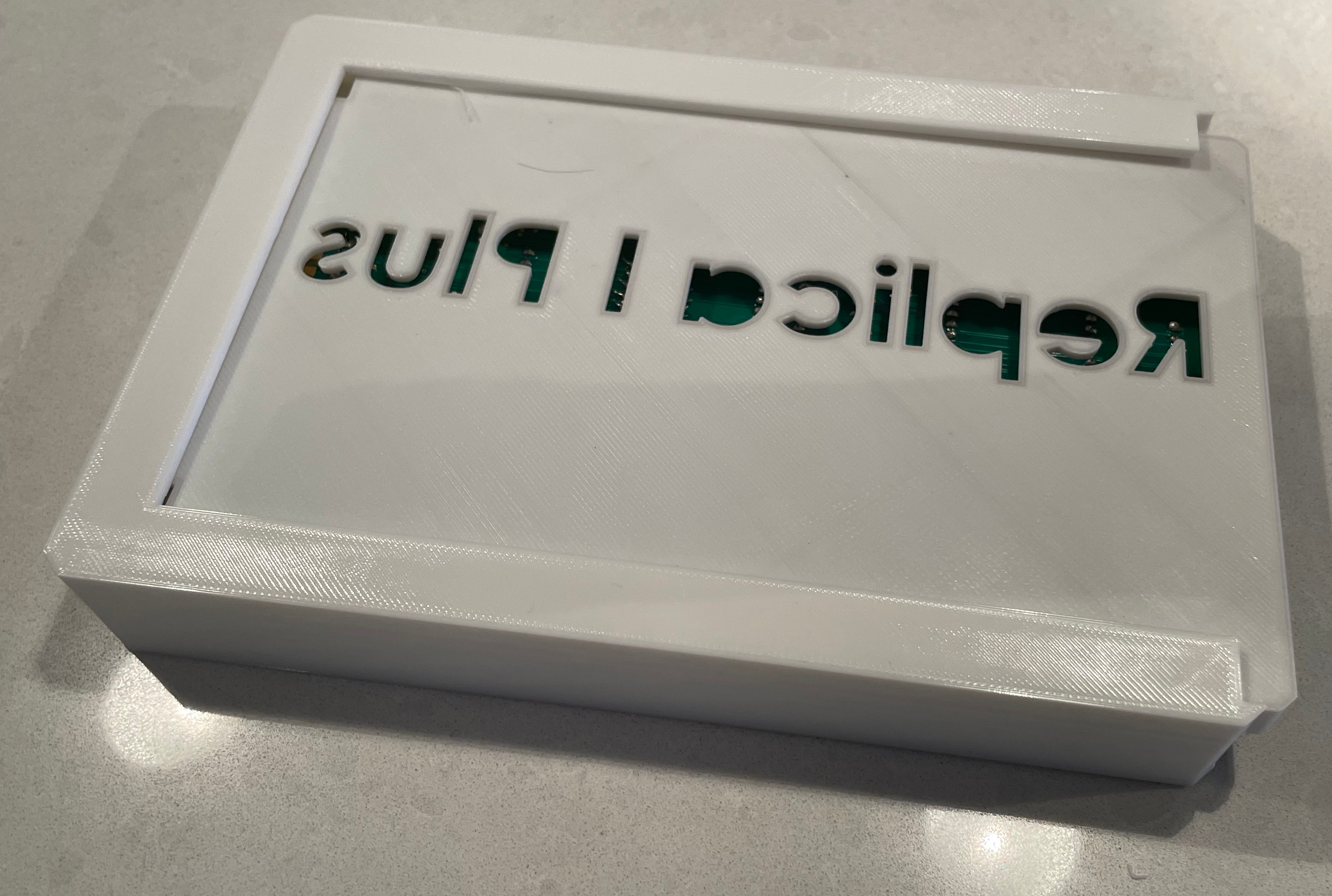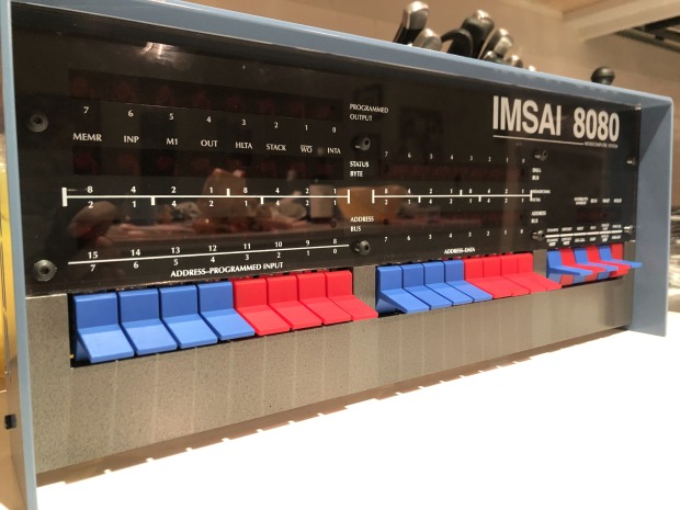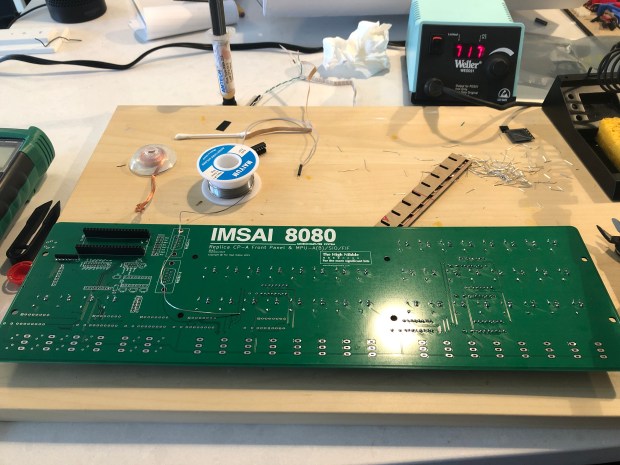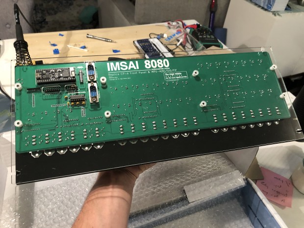
The High Nibble is back with another fun retro computer kit. This one of the Cromemco Z-1. I reached out to the creator of the kit when it first went up, and he asked if I was sure I was interested. The kit is 99% the same as the IMSAI 8080, including most of the components except the acrylic panel and new firmware. The kits are so similar the PCB for the main board is the IMSAI 8080. I enjoyed the last one so much and wanted to support the creator (not to mention a new kit means more blinky lights on the shelf); thus, I ordered the new kit.
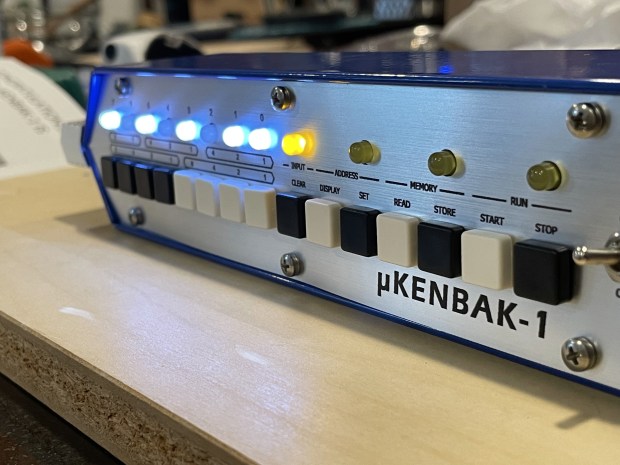
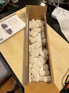
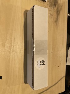
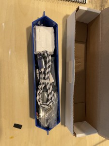
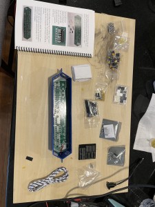
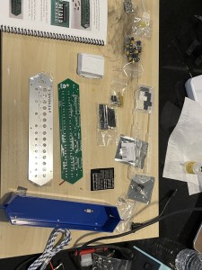
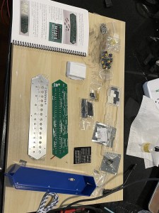
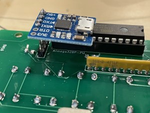
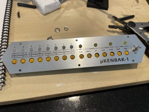
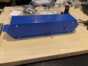
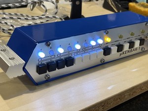
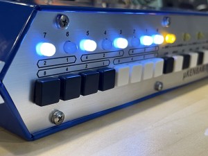
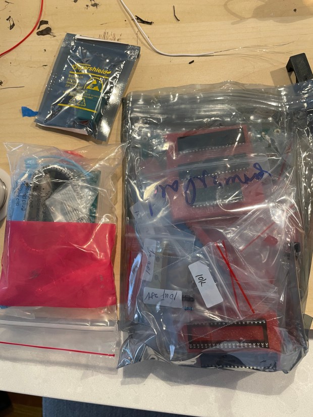
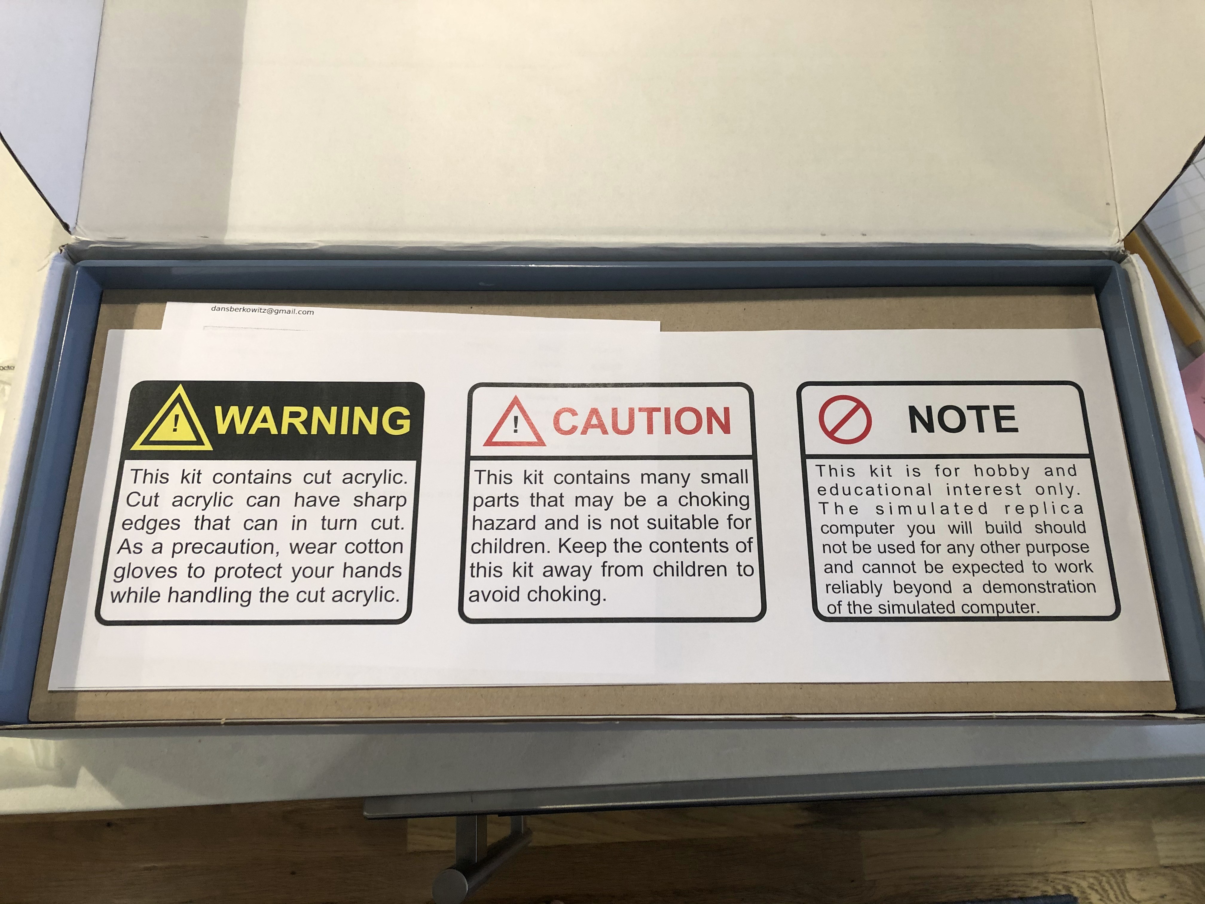
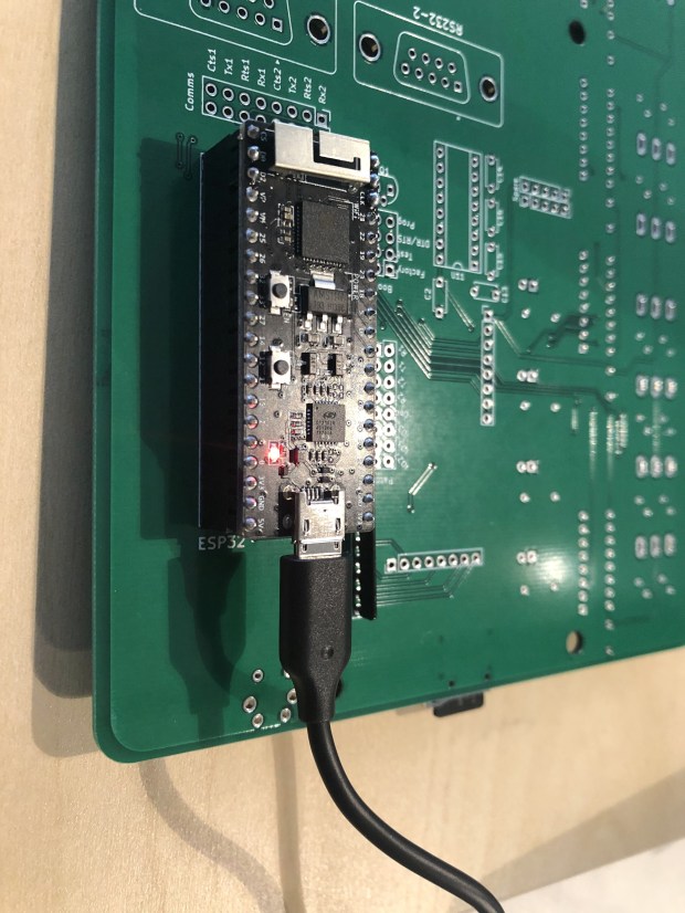
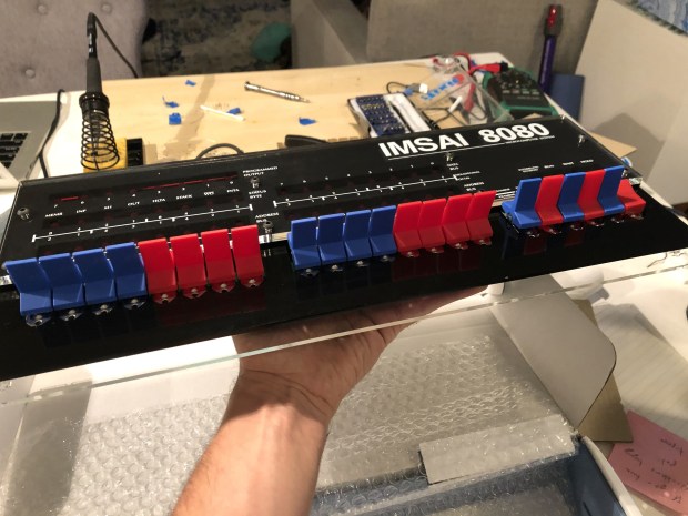
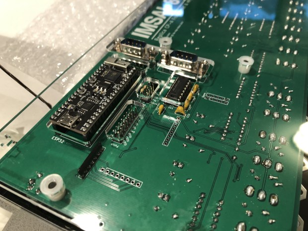
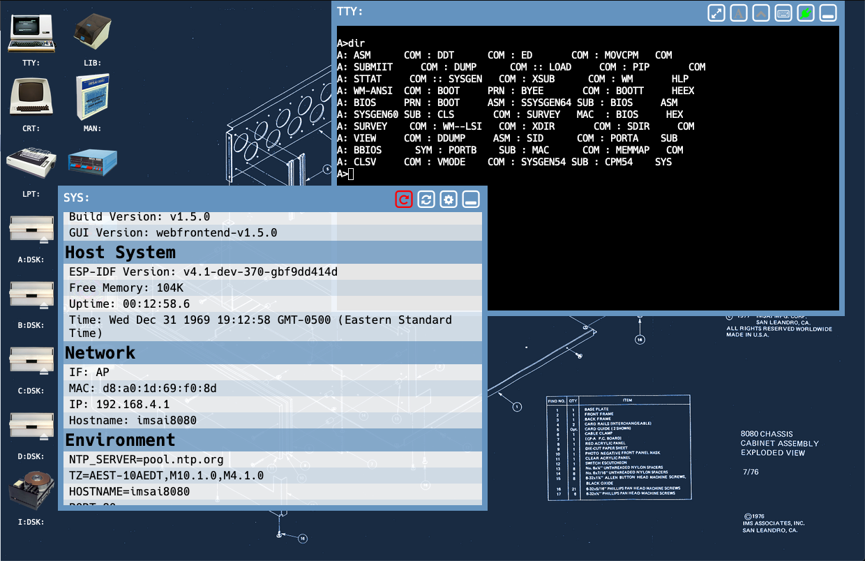
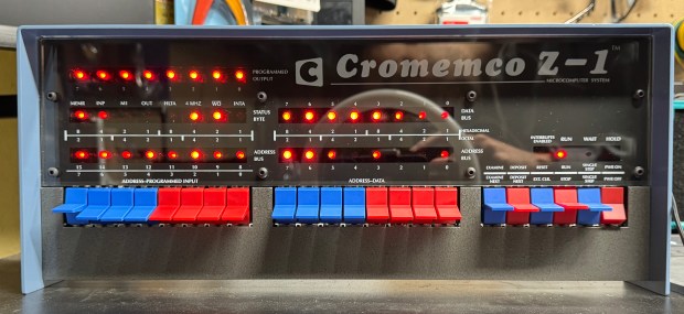
The kits are not cheap at $300, but come with everything you need, including a ready to go controller. The packaging is done well with individually slotted spots for each switch and IC in cardboard. The metal case is a nice touch. And just like before, the firmware is fantastic. You get a full web interface, external serial ports, the gorgeous front panel, and the system can update over the air update via Wi-Fi.
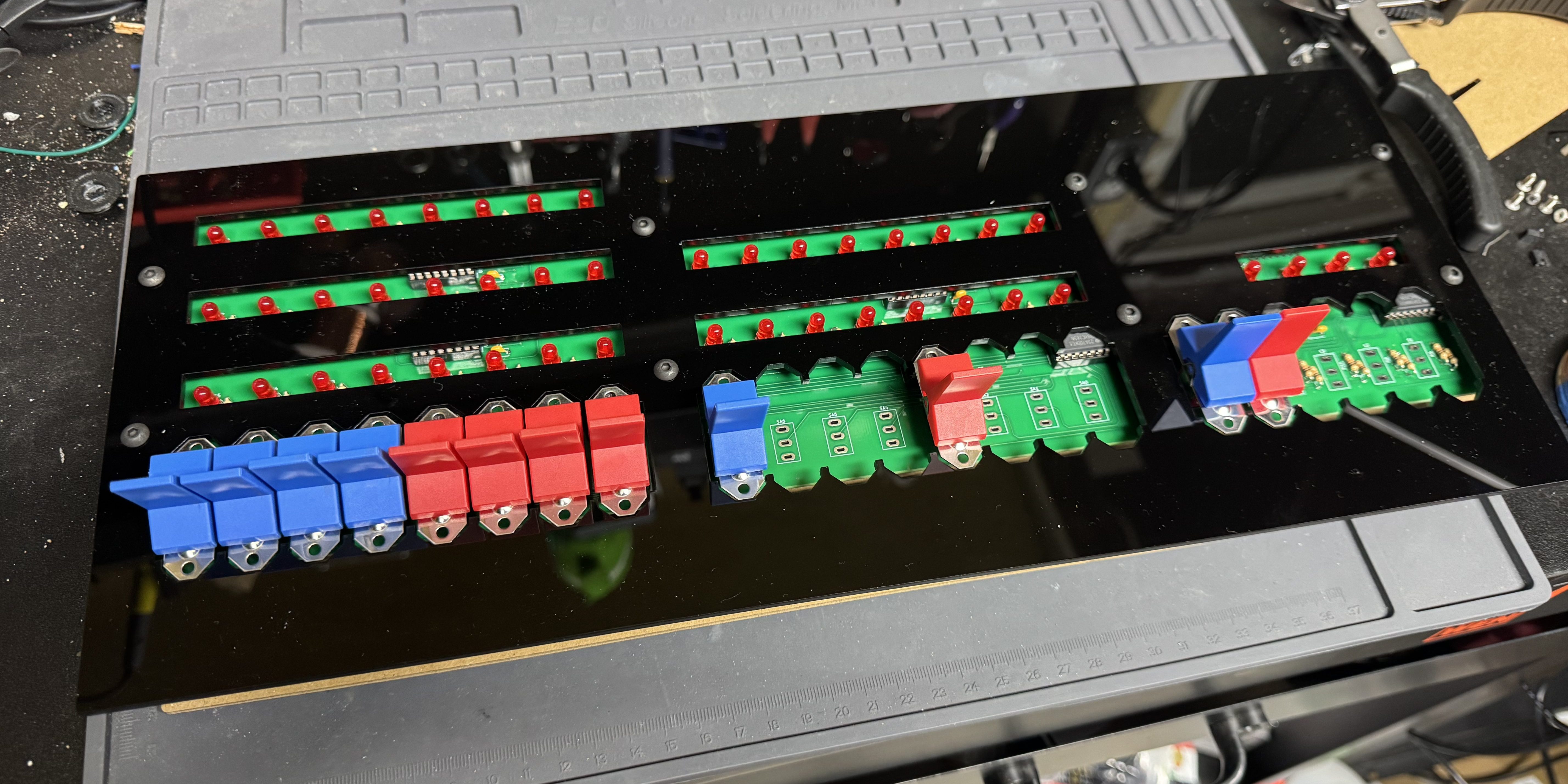
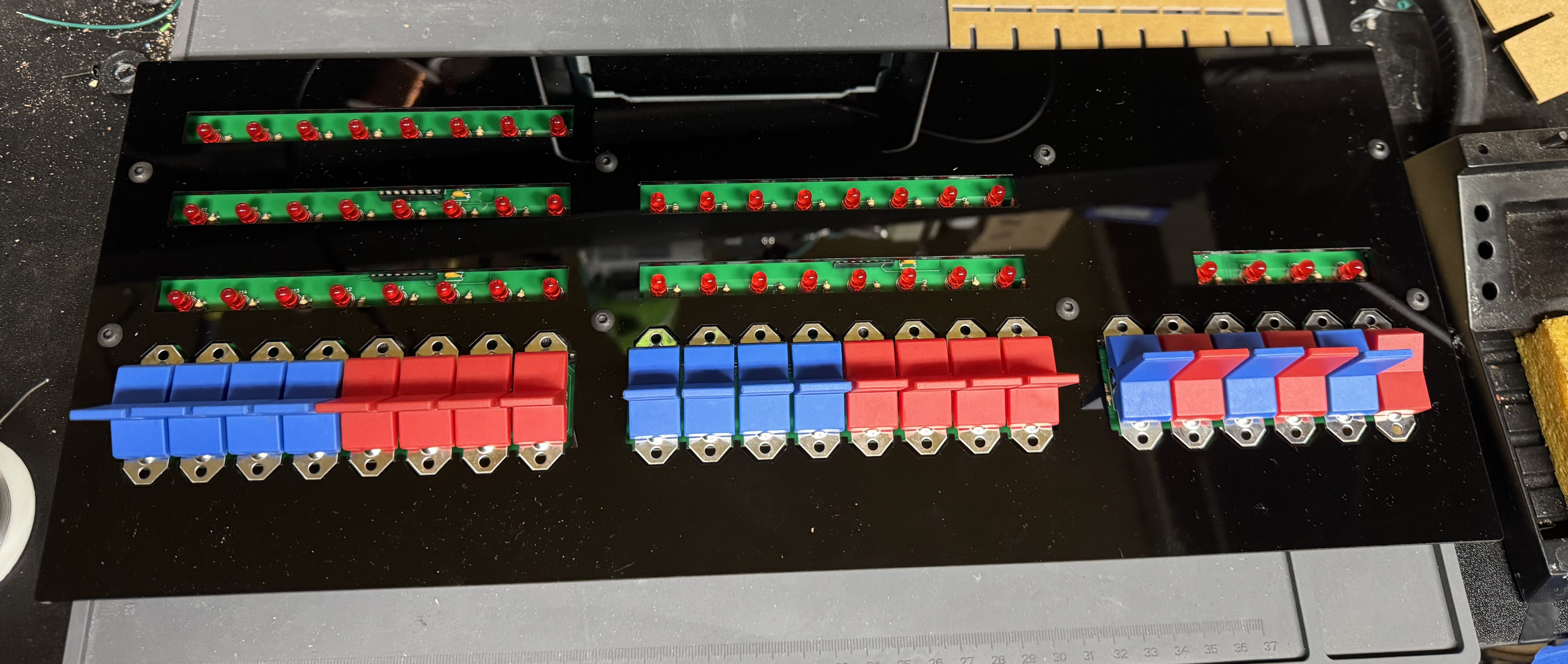
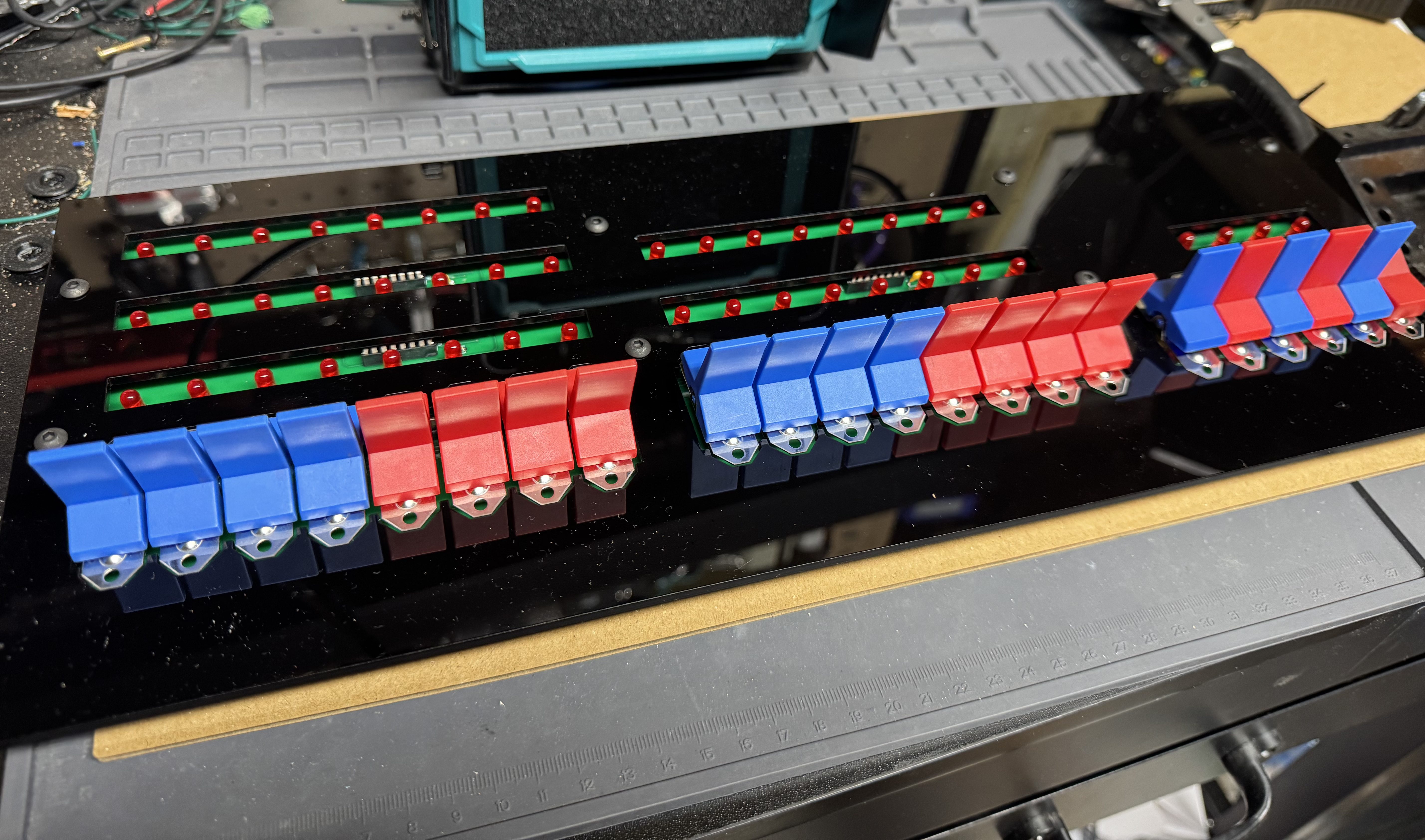
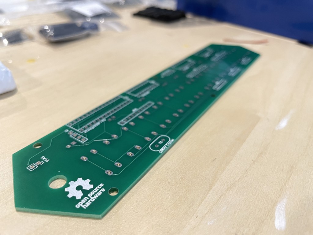
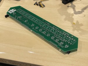
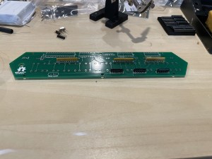
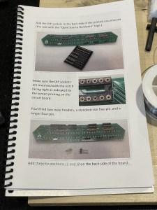
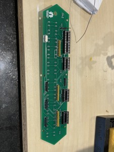
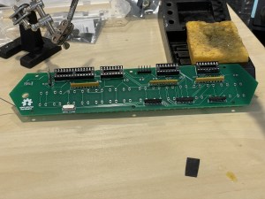
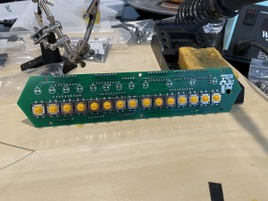
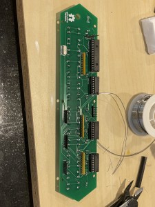
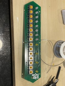
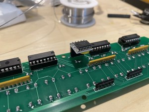
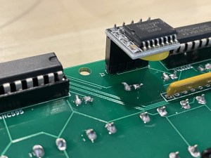
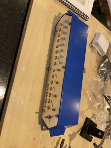
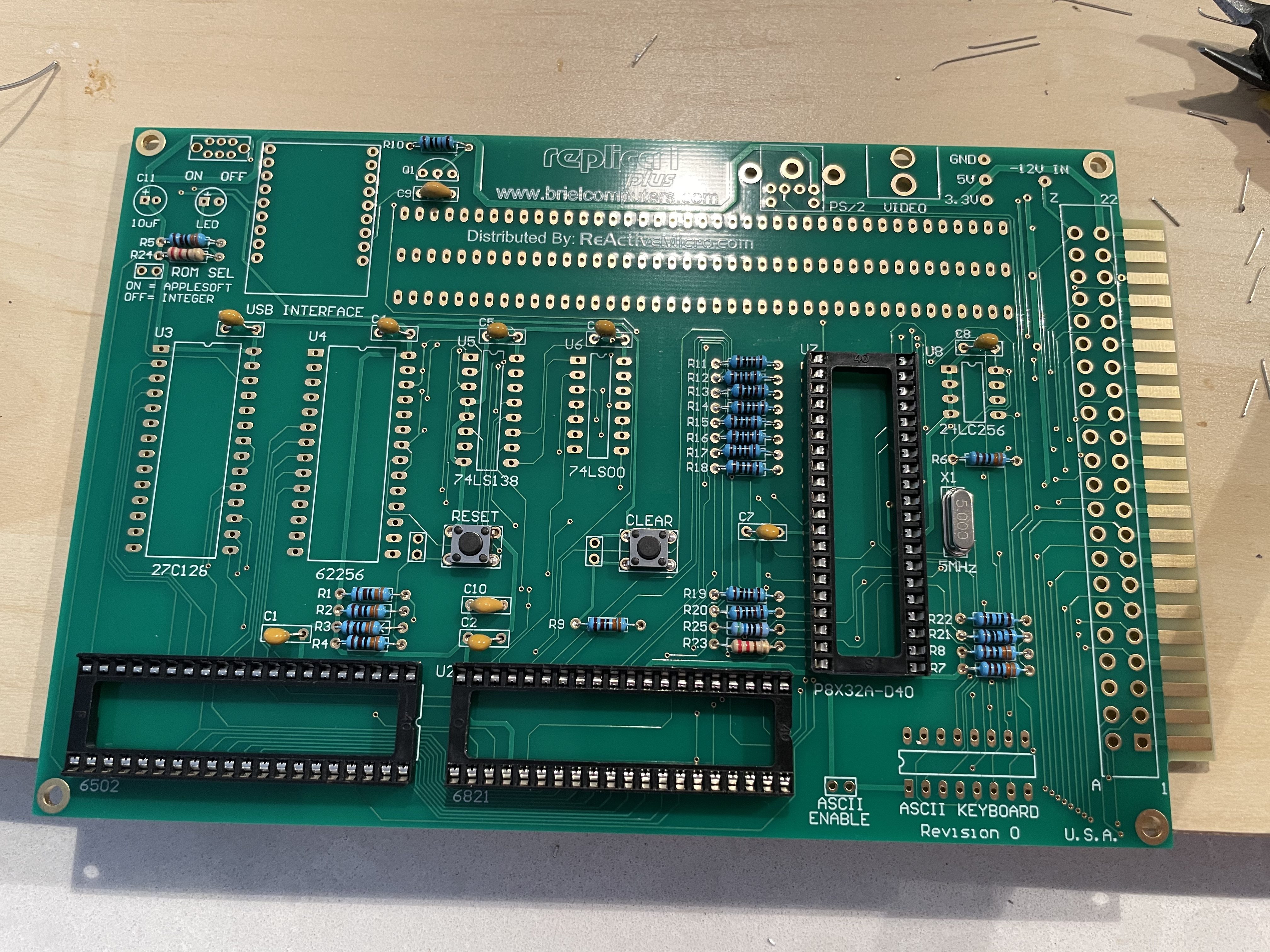
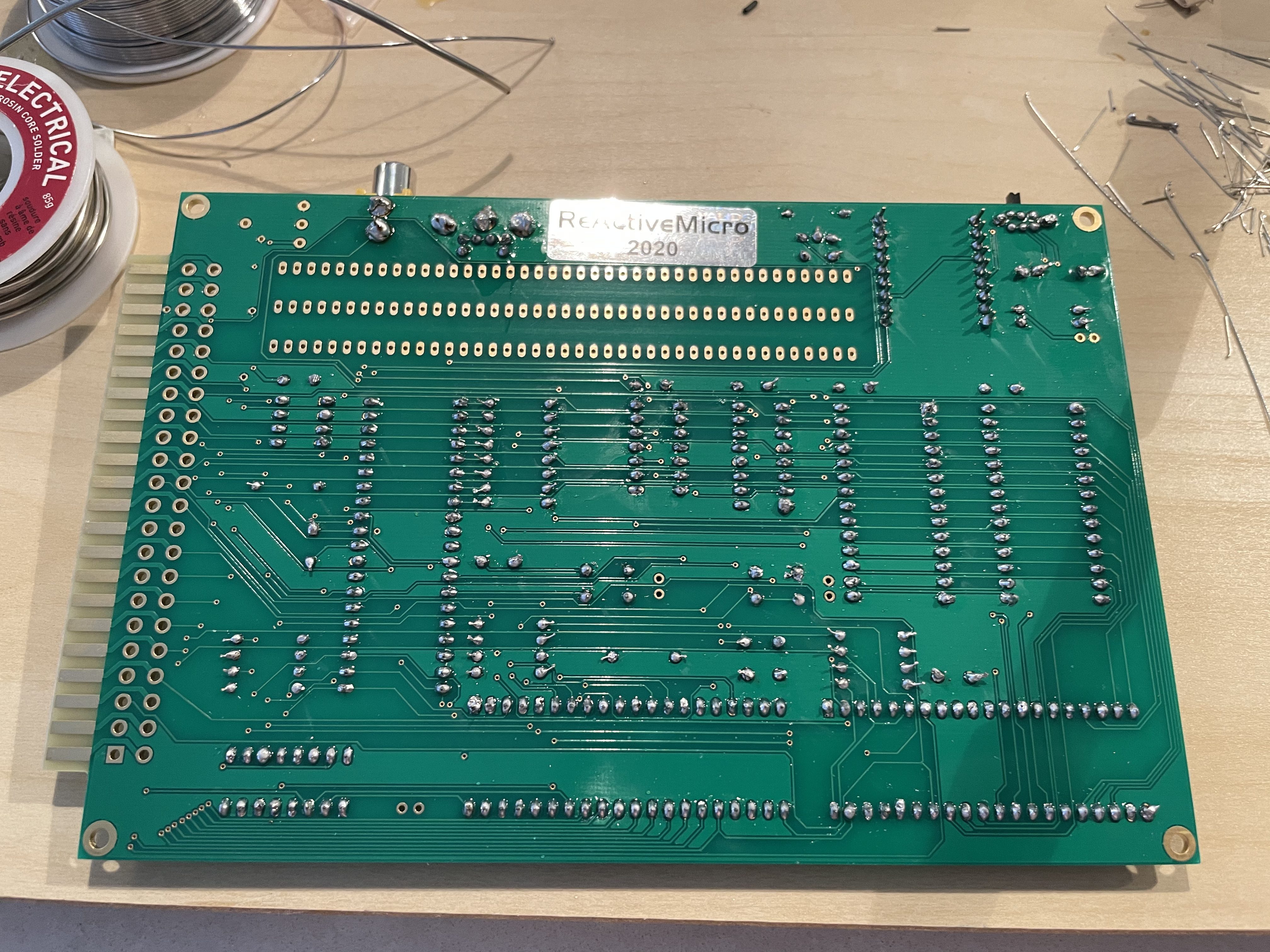
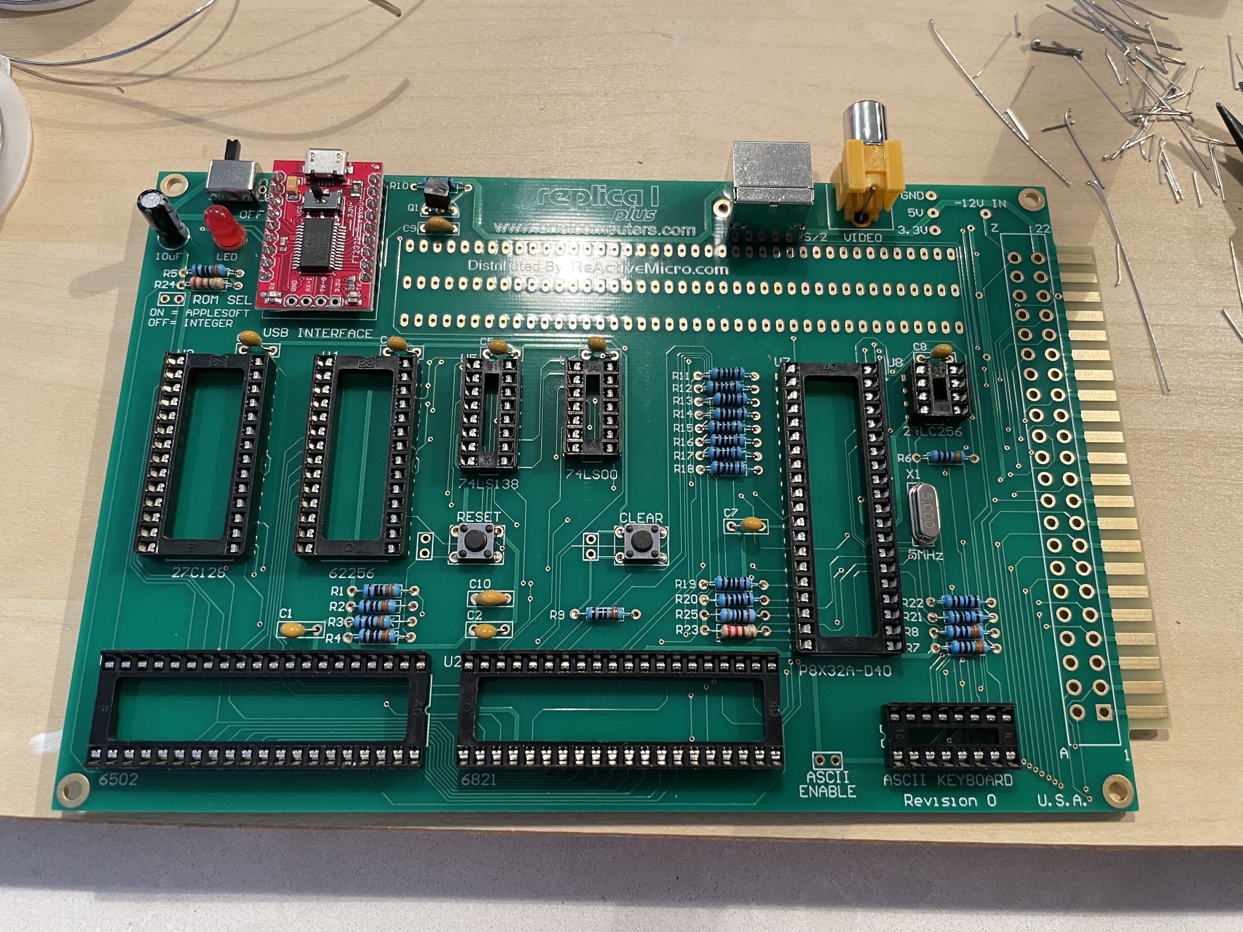
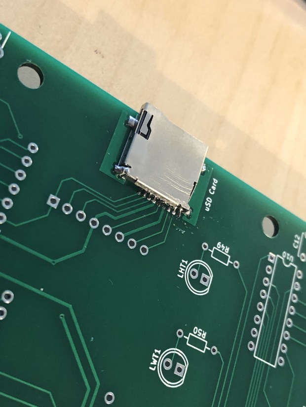
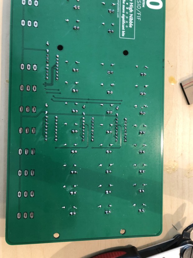
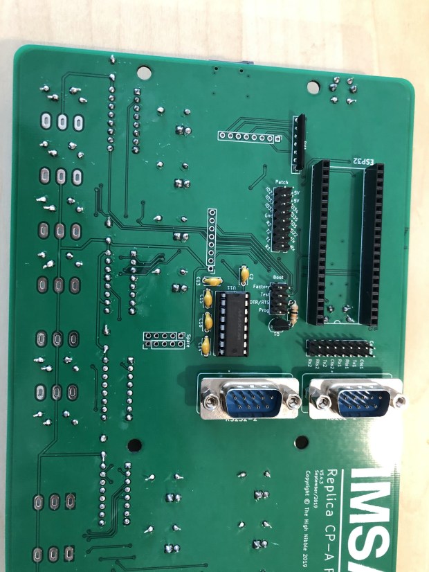
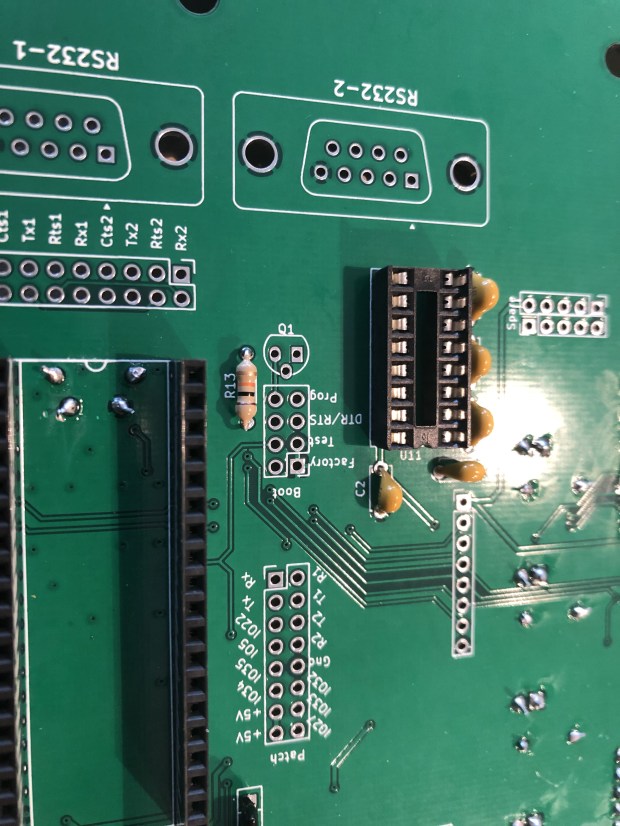
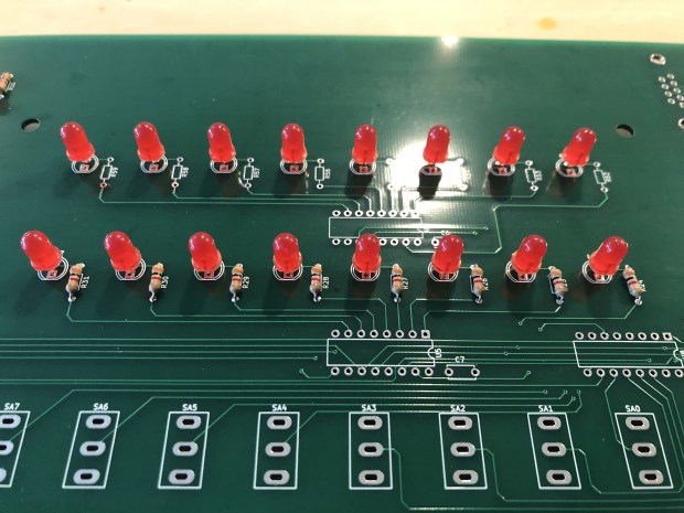
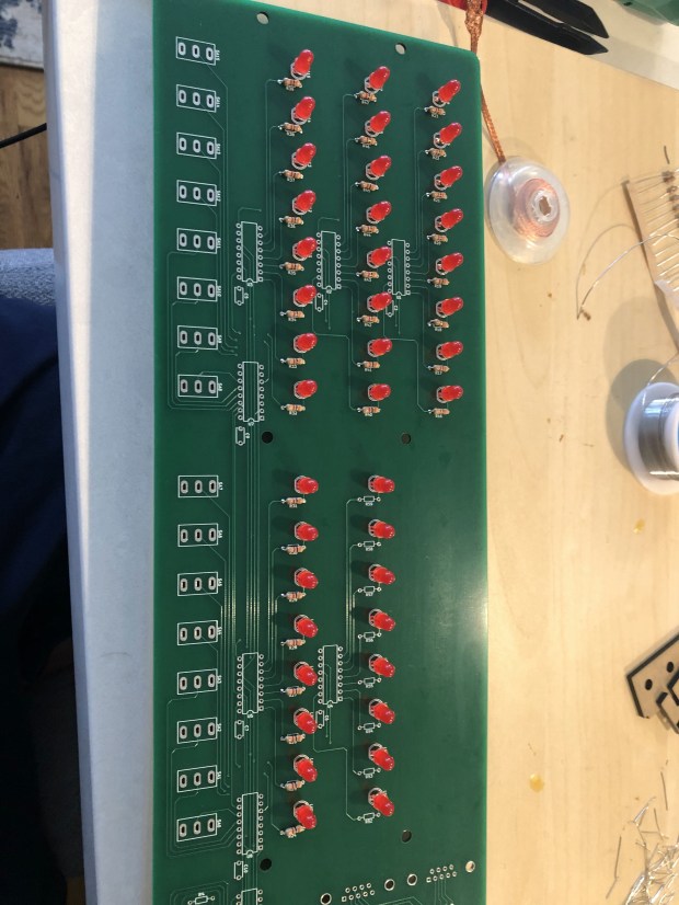
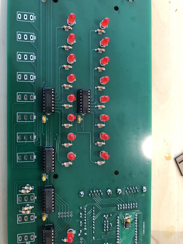
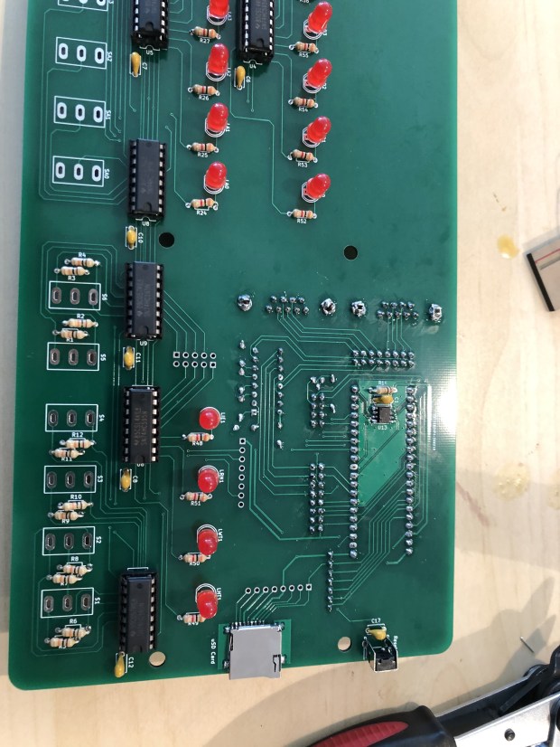
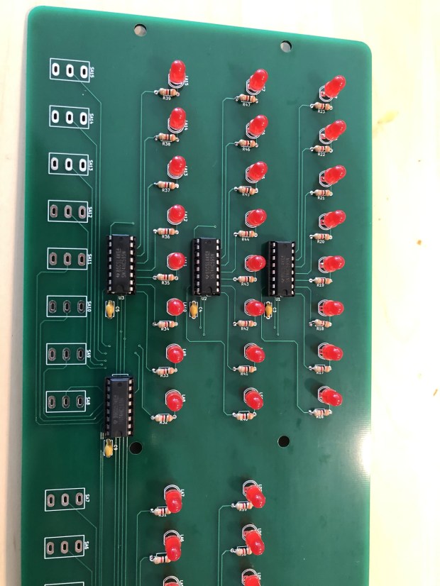
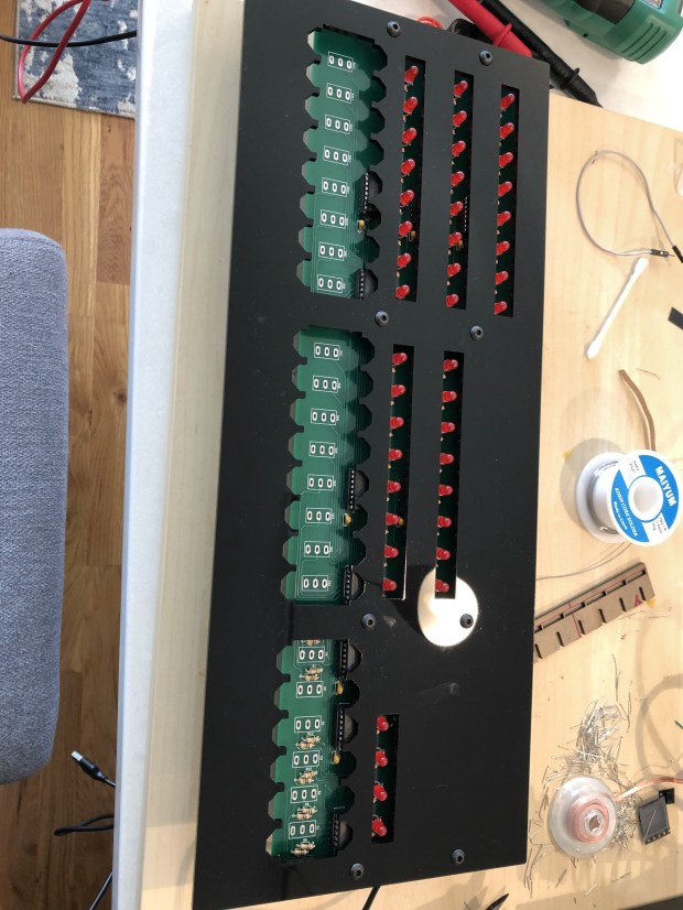
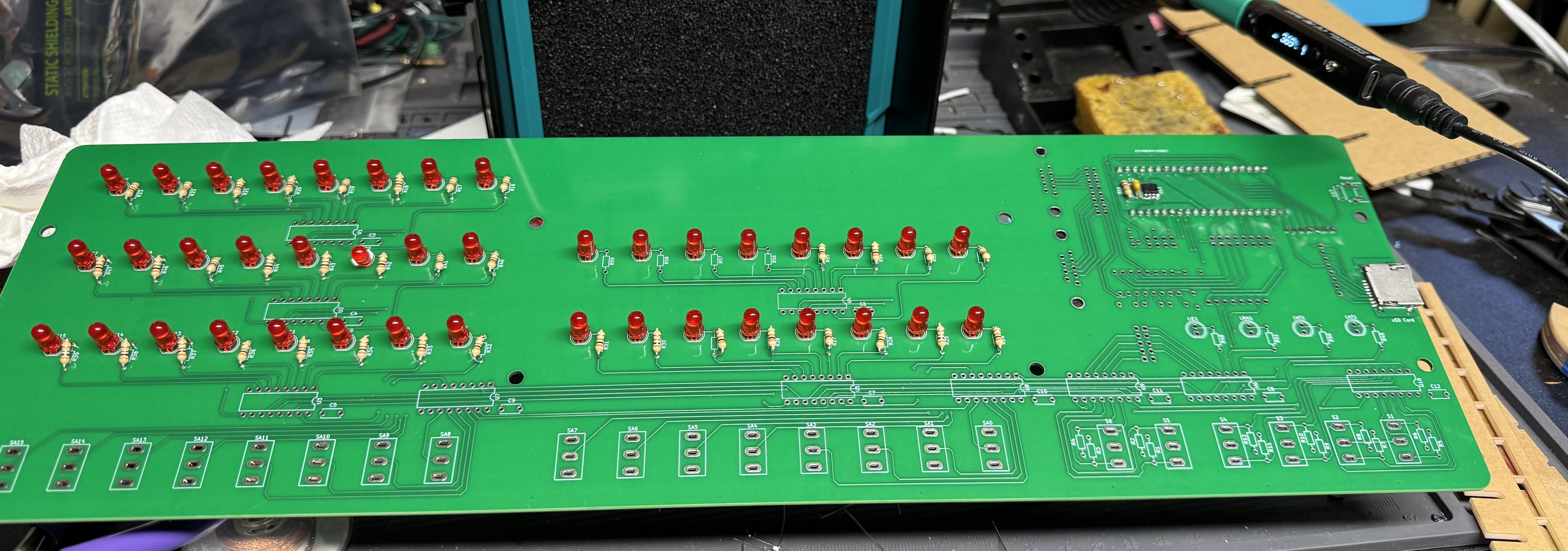
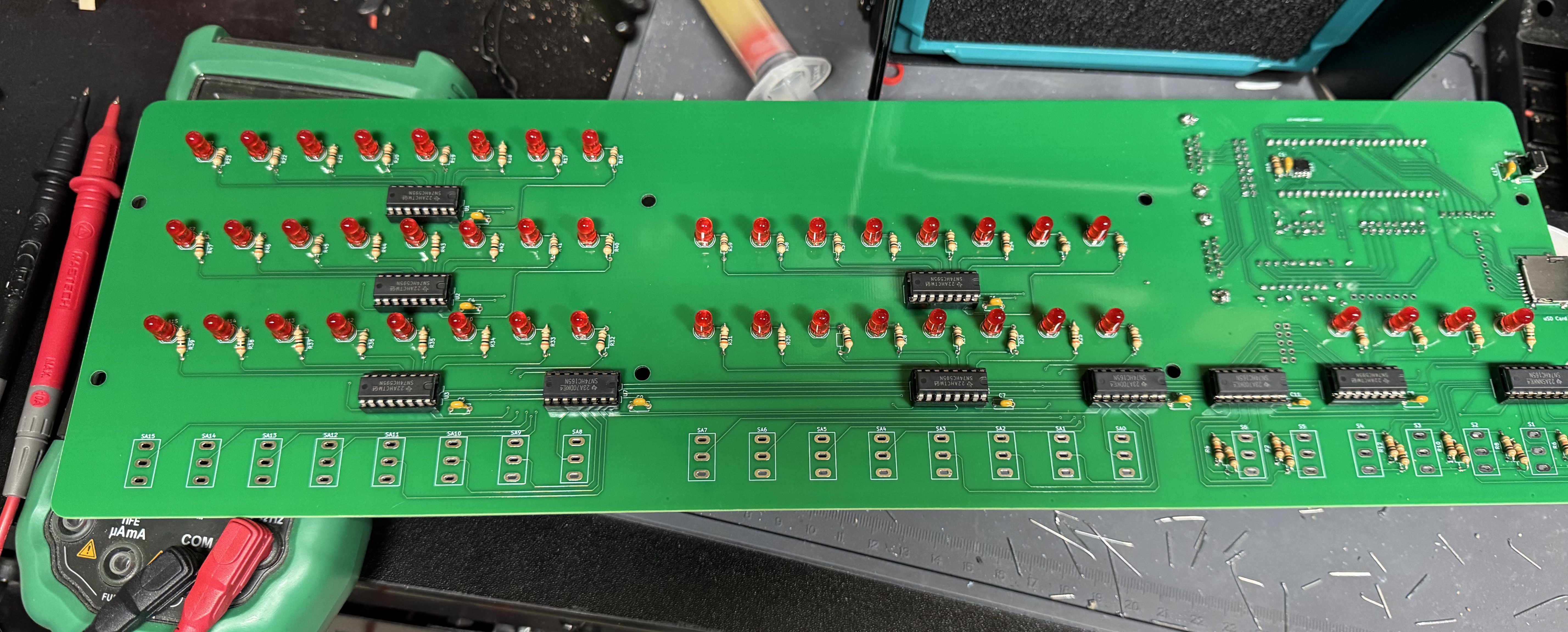
I won’t go too in-depth about the kit because it is so similar to the other one. The soldering is not too bad, the process starts with one small IC that has to be soldered in the front of the pcb, after that things like sockets and LEDs are easy, large, and straight forward.
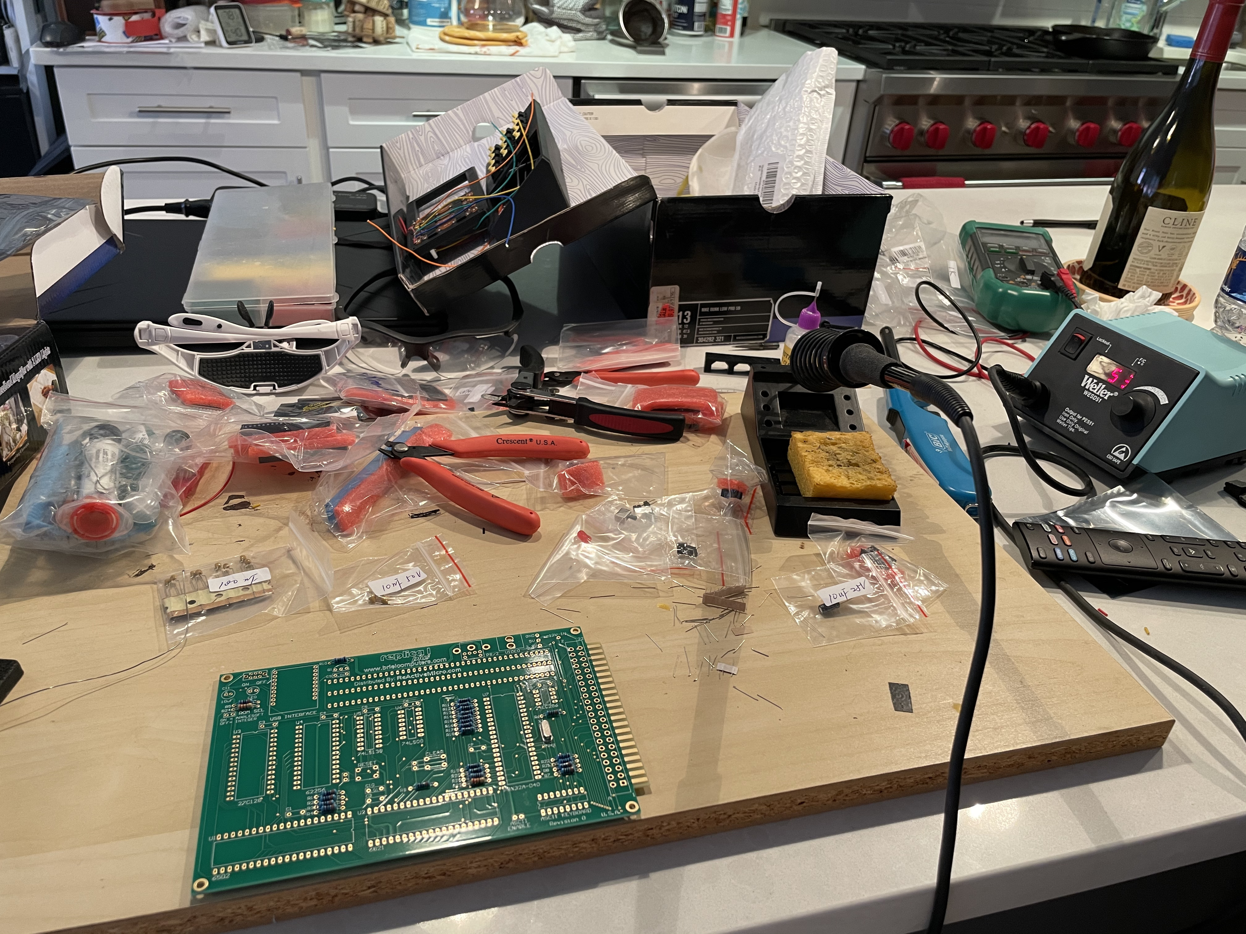
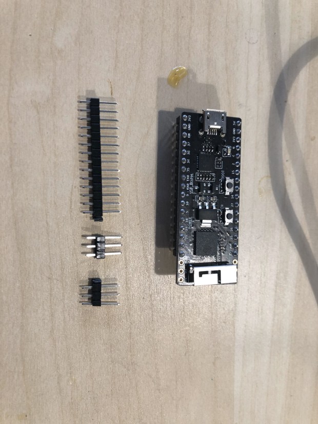
I got a new soldering iron, the Pinecil from Pine64. This was my first project using it and I found it delightful. It’s smaller than my old iron, making it easier to handle. It’s advertised as a “smart” soldering iron which means when you put it down in a holder it quickly cools when not in use. A very nice safety feature.


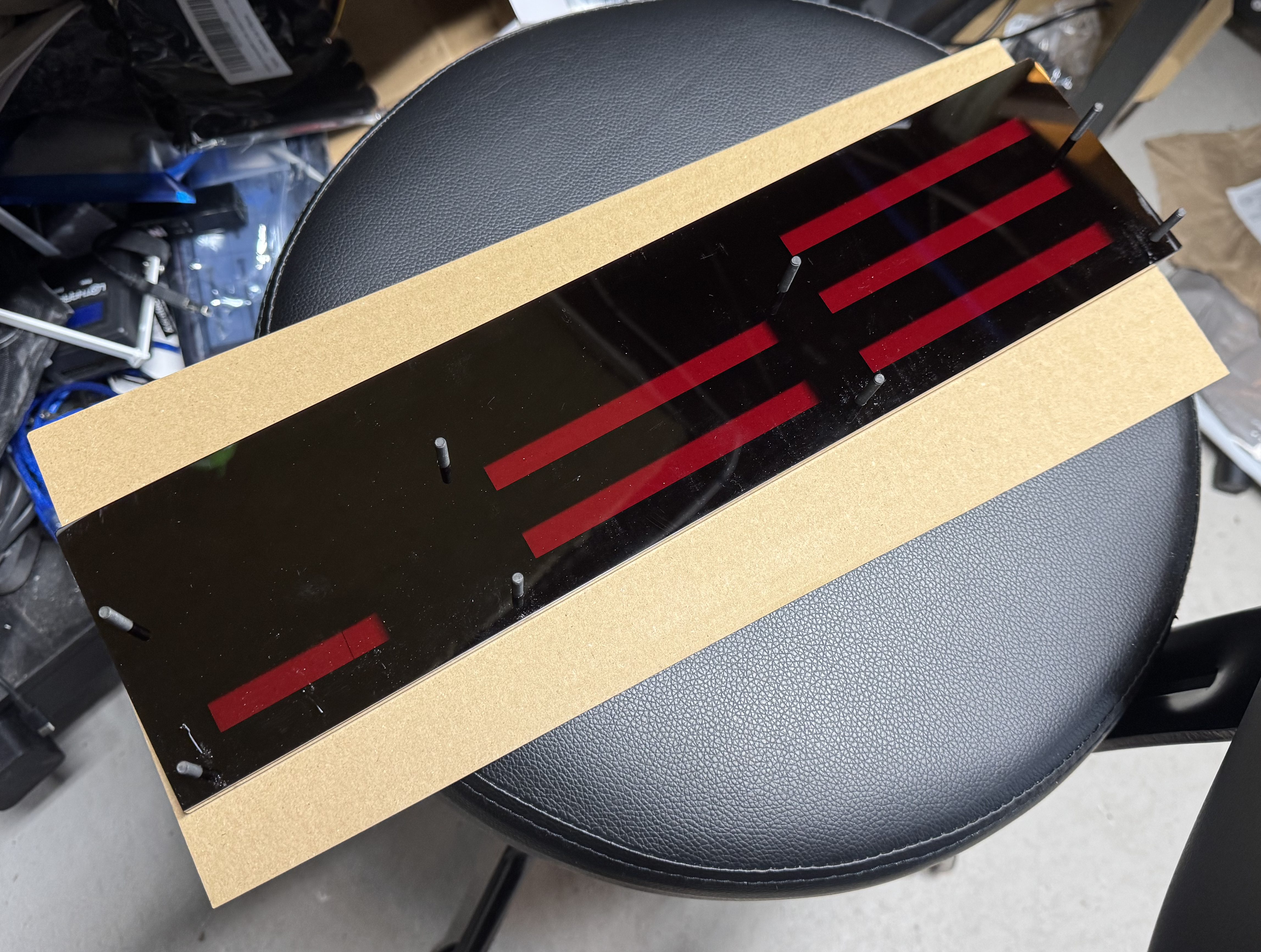
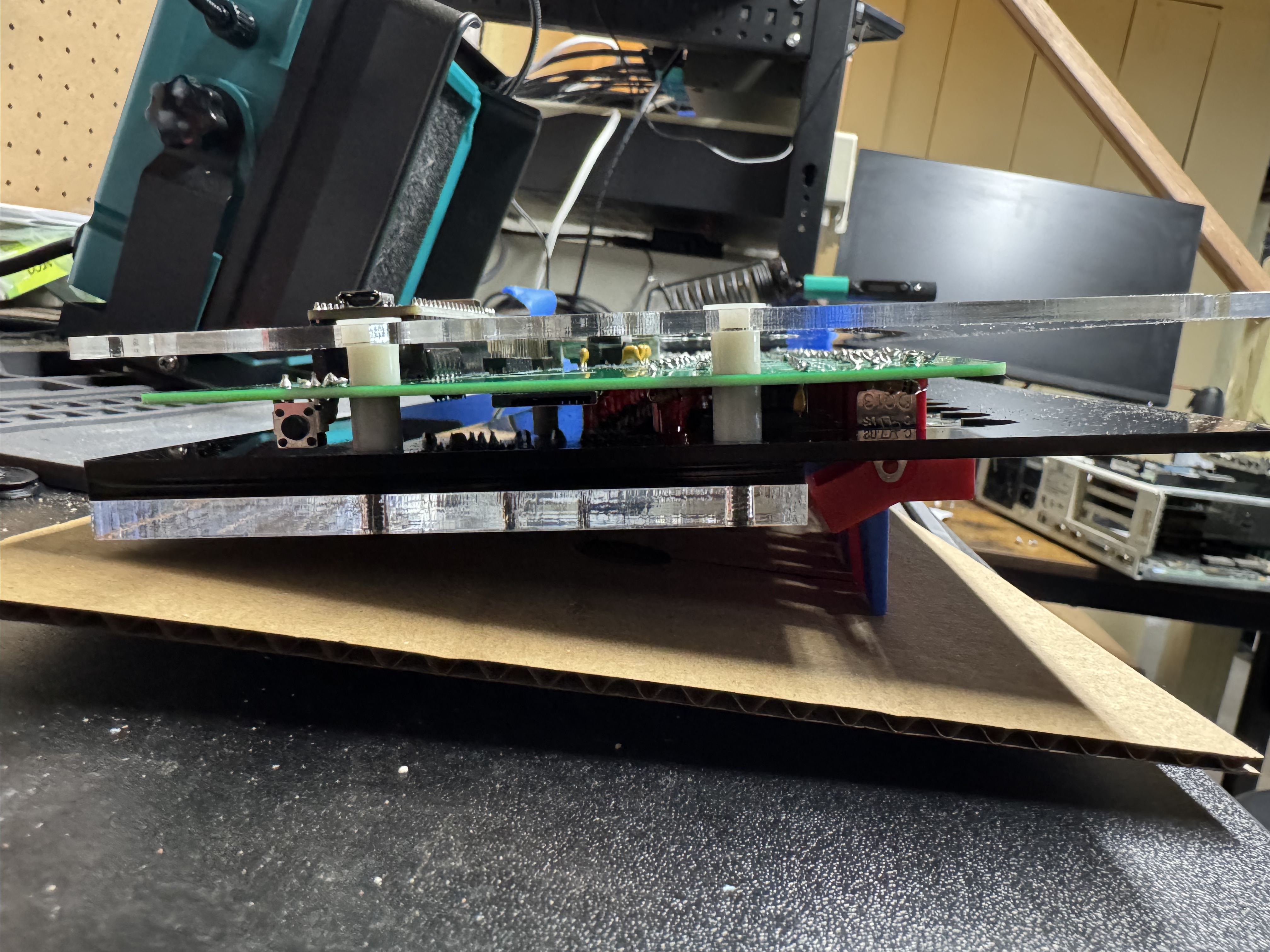
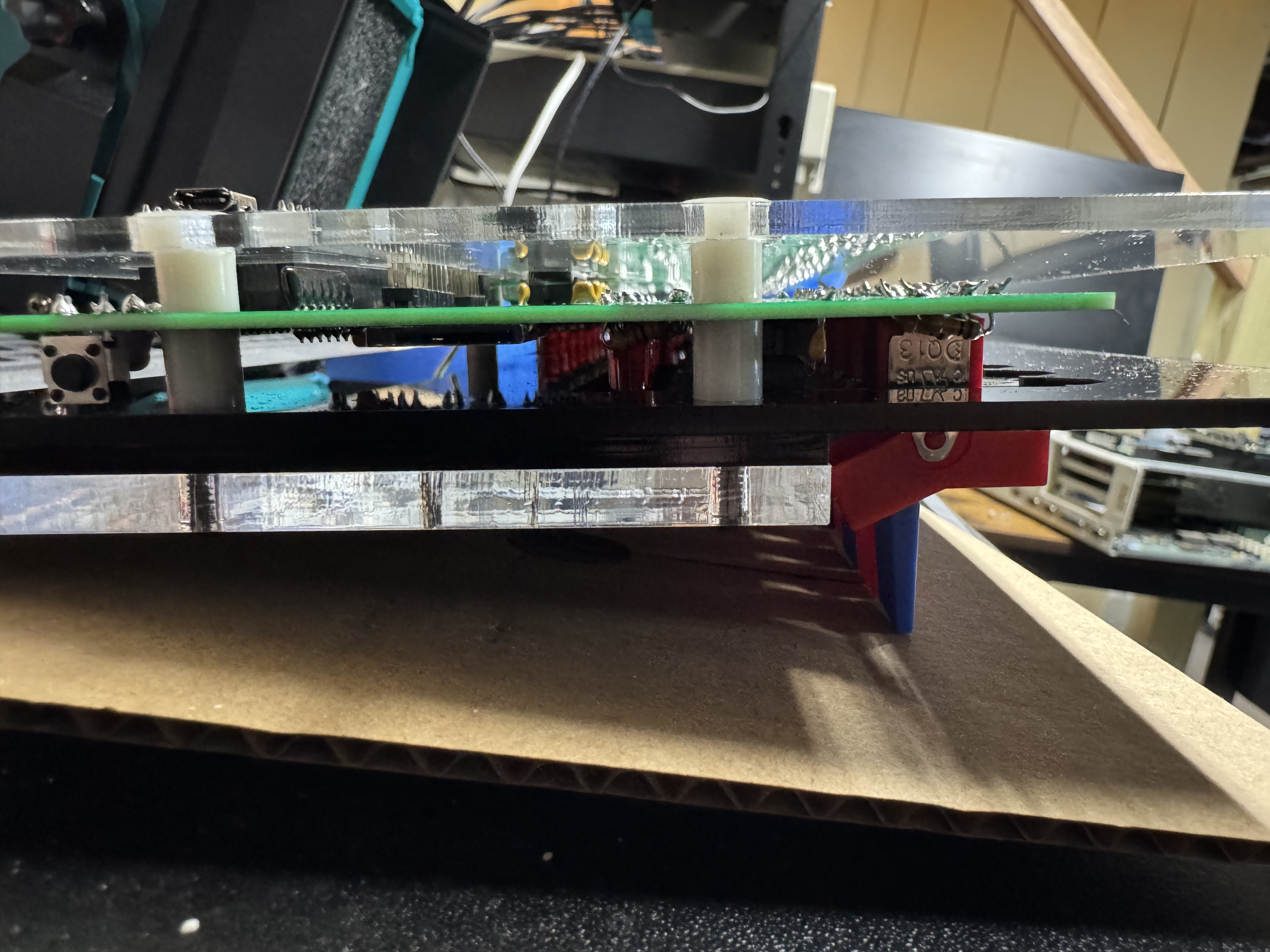
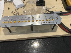
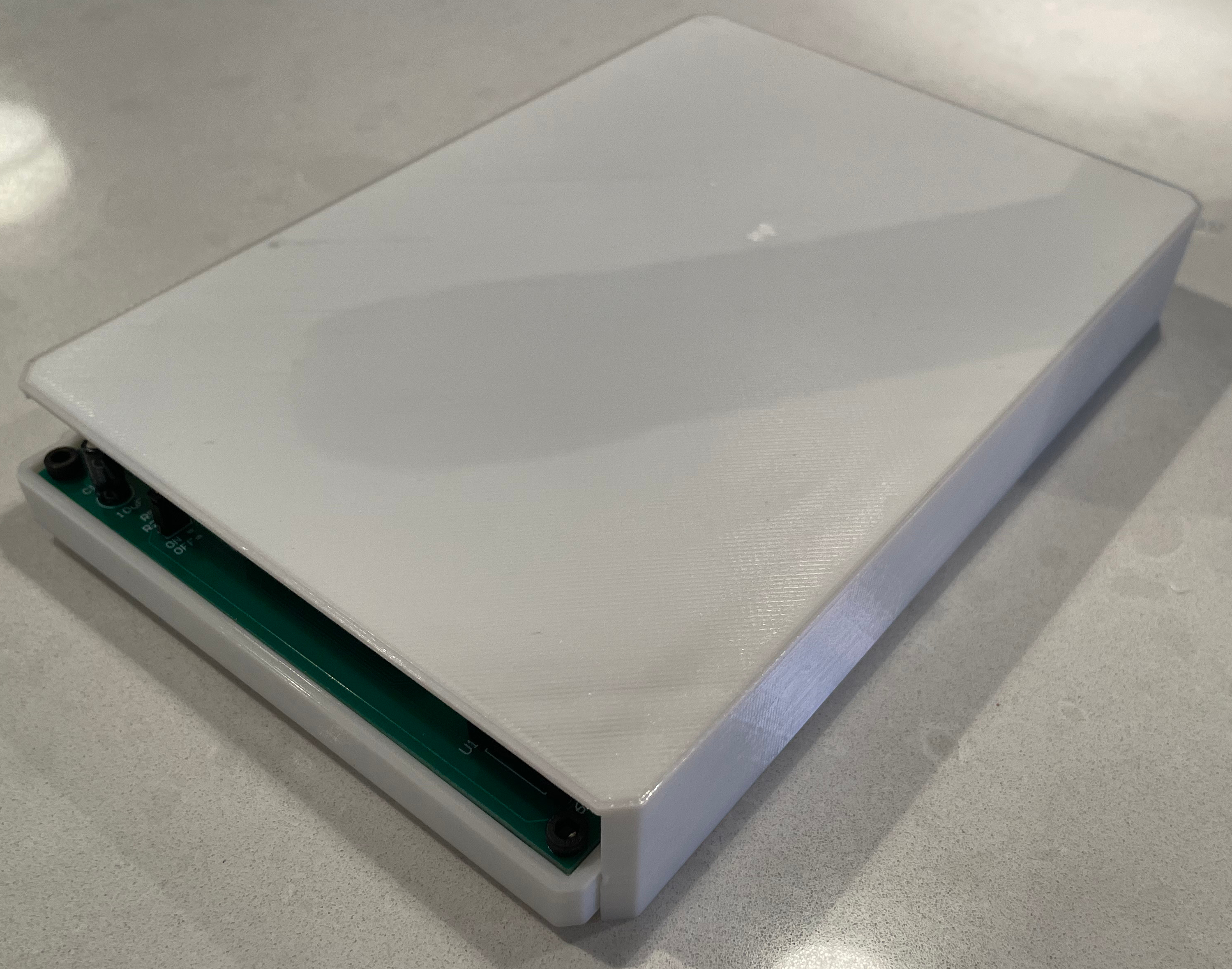
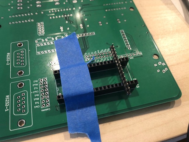
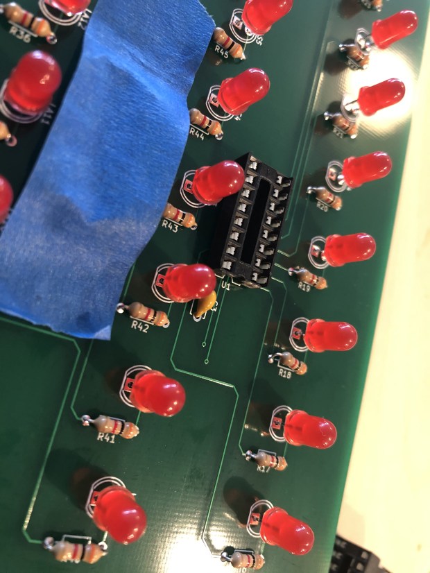
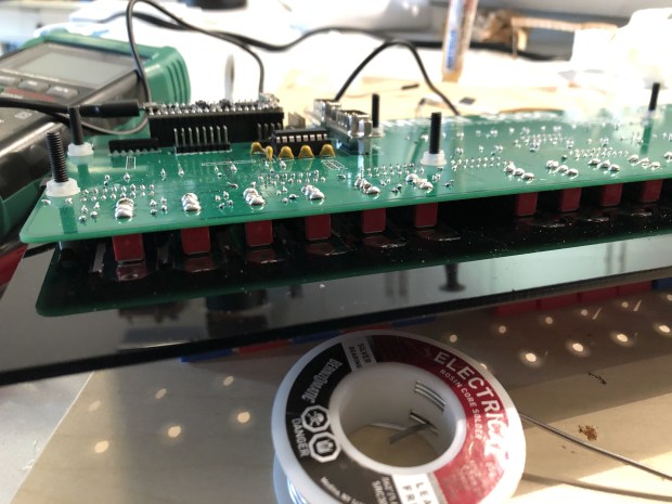
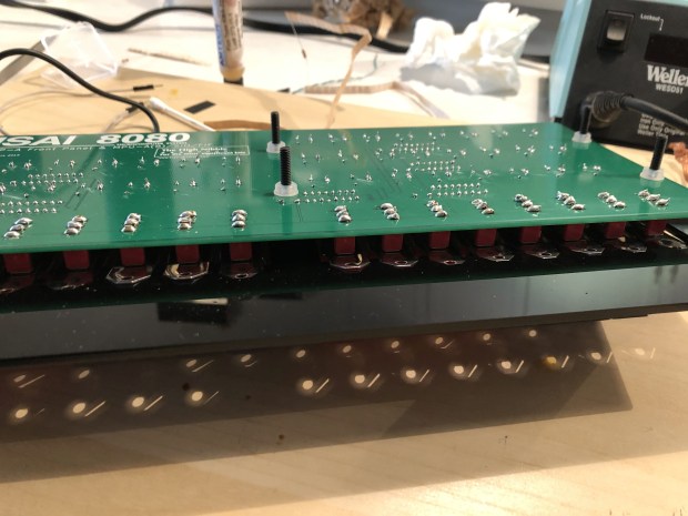
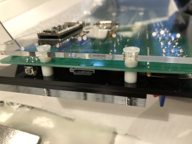
The parts of the last build that were difficult are here too, having to put the system together as a sandwich of acrylic and circuit boards it’s a bit tricky, but once you get it in the right spot tightens up easily. Tape helped keep the build aligned during assembly.
The website for the project has a lot of good information, https://thehighnibble.com/cromemcoZ1/. There’s also a helpful YouTube video, same one as the IMSAI kit, that walks through the construction step-by-step.
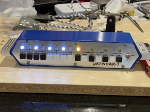
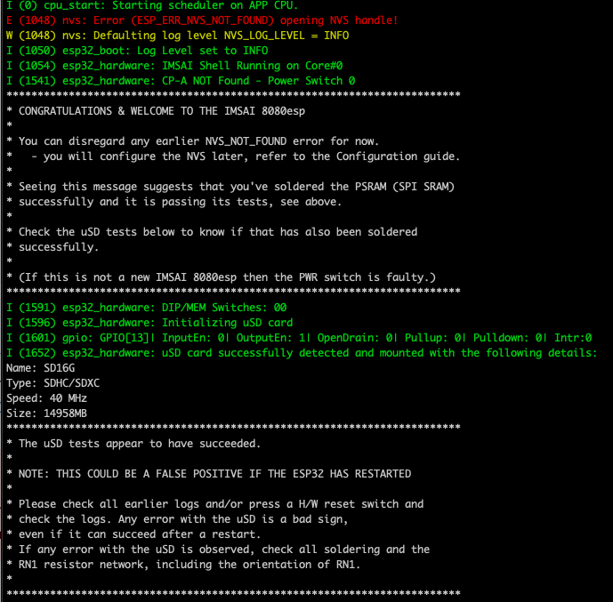
The main step that gave me an issue was when you get to Testing, the LS2 light would not come on. After looking in the forums, https://github.com/orgs/thehighnibble/discussions/120, turns out that is a difference in the firmware, and it is not supposed to come on. With the video being for the other kit, it is not mentioned.
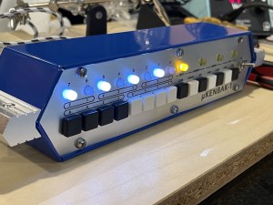
Overall, another great kit, and another fun system to add to the collection!