Repo: https://github.com/palantir/onb-classic Docs: https://palantir.github.io/onb-classic/
Background
I have been on a slow mission to open source some of the projects I have worked on over the years. The next project after the IsoFileReader actually predates that other project. ONB-Classic has the ability to serve files directly from an ISO without extracting the ISO, to do this we utilize IsoFileReader. That feature required me to open source IsoFileReader first. ONB-Classic is a fork of the OpenNetBoot project I started around 12 years ago. The project originated with having to PXE (Preboot Execution Environment) boot systems via the network, and I wanted to be able to use Proxy-DHCP (more on that in a second) to boot anywhere no matter the infrastructure. This allowed any sysadmin to pop up a PXE server, quickly image systems, and then tear it down.
When I started this project we were imaging Windows 7 machines with Symantec Ghost (what a time to be alive). It wasn’t new at that time, but it had a built in utility from 3Com which allowed us to do Proxy-DHCP, and PXE boot systems. Proxy-DHCP is when you have an authoritative DHCP server giving out addresses on a layer 2 segment, but then have a secondary DHCP server which jumps in after the Server -> Client offer broadcast and offers up boot information (PXE data) which the client then combines to boot. This has its own RFC as part of DHCP, and works on all (with some difficulty) PXE roms.
Concept
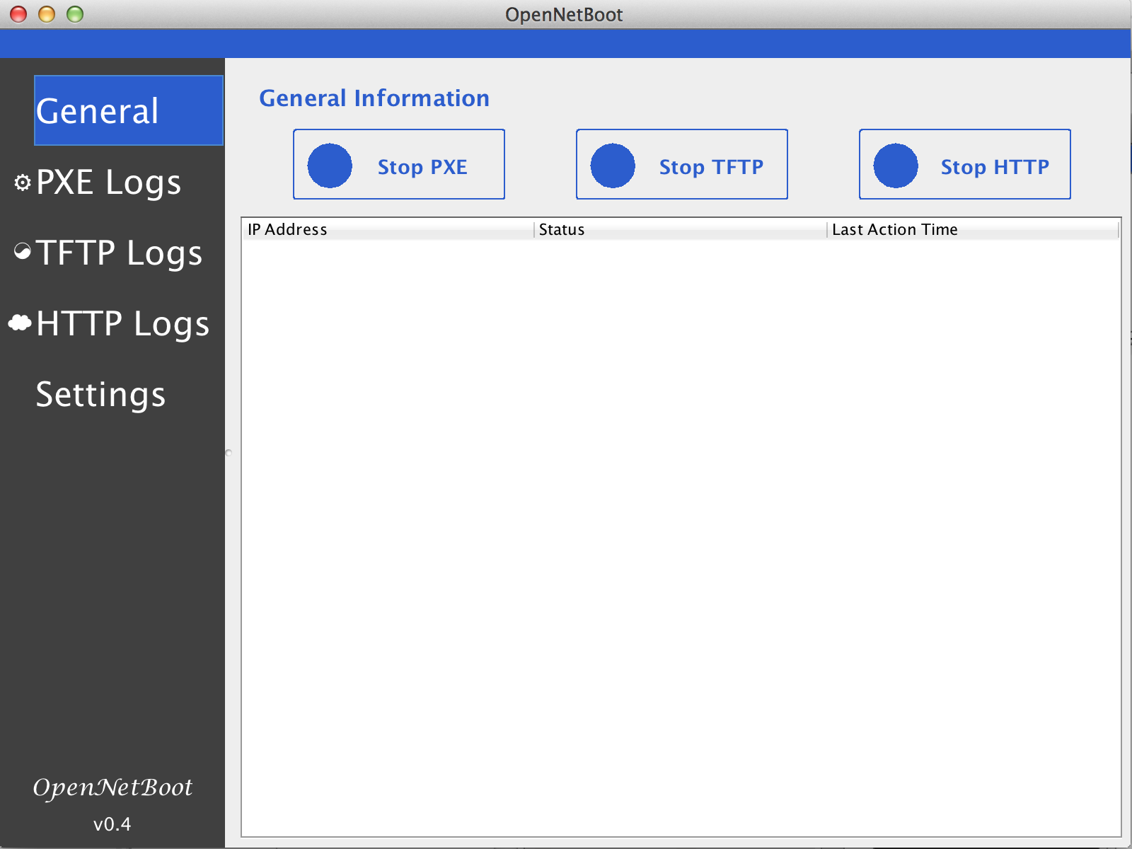
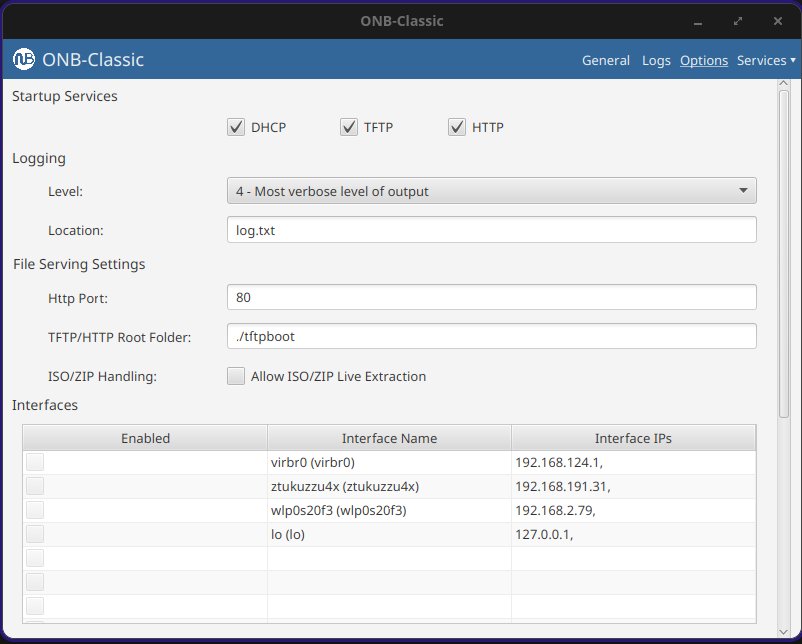
The main concept of OpenNetBoot was to bring PXE, TFTP, and HTTP services together into a simple app, allowing someone to stand up an imaging system or Linux installation system anywhere. I also always hoped to open source it, hence the name. The program started as what you see in the repo. It became classic when I had the idea to make it into a web app, and that web app became more of a platform with plugins that could allow different types of system installation. That greater platform was more work specific and I may write about it later, but was very mission focused for building servers at work. It hooked into different systems like server ordering and customer delivery.
This project was where I really started loving lower level programming, and the things you could do if you owned the whole stack. This allows you to have greater insight into the boot process, in addition to doing some fun tricks with the protocols because we control them. I can send the client to different images depending on data I get at different stages in the pipeline, watching the client progress through the boot stages.
Development / Boot Flow
There were bumps along the way. The system would be able to boot one system, and then not work on the next. Some of this came down to vendors **cough** Realtek **cough**, not following the RFC and requiring extra bytes where there are not supposed to be any. We later moved from shipping all BIOS systems to UEFI, which proved to be a new generation of PXE roms that were more picky. The project was also written in Java, this allowed me to run it on any operating system, but this also led to issues where different systems would treat sending to a broadcast address (255.255.255.255) differently.
At this point it may be worth going through the boot flow, and how I always used ONB. A server boots, asks for DHCP, your local network gives you an IP and ONB comes in and gives boot information based on the headers in your original DHCP request. Are you x86? ARM? Are you a BIOS system, or UEFI? Then we return the address to a boot server (ourselves) and a file to load, usually iPXE.
I have been using iPXE for the whole life of this project, it’s a great boot rom except it never was SecureBoot signed, forcing us to disable SecureBoot for PXE operations. That is until recently! iPXE project after a decade got their rom signed by Microsoft! I have been very excited.
Now that iPXE’s address is given, the client reaches out over TFTP to the server to pull the rom. TFTP is very slow; the client requests bytes of a file over UDP, we send bytes, the client acknowledges and requests next bytes. There is no windowing, and if the link is full because let’s say 100 servers are booting, some UDP packets are dropped, forcing a restart. That makes our goal to leave TFTP as quickly as we can. Once iPXE is loaded, it does a new DHCP request, and gets Proxy DHCP information again, but this time with an iPXE system id. Now we serve them a menu file instead of a boot rom. From now on, we can send them data in HTTP format, which is much, much faster and unlocks things like loading large kernel roms before the heat death of the universe. Loading 100MB Linux kernels at 500kb/s is not feasible for a production environment.
As mentioned, the application is written in Java, this allows it to load anywhere, and the JavaFX UI to work on any of them. Over the years things have changed; JavaFX used to be included in Oracle Java, and as we all moved to open source Java it became its own package. The application back end became heavily multi-threaded with threads dispatched when clients connect. Multi-threading dispatch allows the DHCP and TFTP servers to handle 100+ clients at a time. When a client reaches out, we get their request, and pass it to a new worker thread to respond. Then we can immediately free up the original server process to handle the next client. There are several core threads and the goal is always to get work off them as quickly as possible and hand it to a sub-worker.
I have gone on to update this application, and write other ones using JavaFX. It’s another one of those – devil you know – situations, where I do not love programming in it, but I know how it works. The SceneBuilder allows you to create the XML GUI templates fairly easily. One of the more complicated parts of the application is actually the logging system. It has to be able to pass log messages to the GUI, or the CLI; and then pass some of them to a text log file. This system also has to take logs from different threads as they fire, and try not to block. It naturally grew over time, and has shown to work well.
While I was deep in the protocols, I went off on a weird tangent: I added a ‘virtual NIC’ option to the command line of the app. It allows you to simulate a client on the network. It generates a new MAC address and reaches out to see how the authoritative DHCP server responds. That was fun because it was the first time I acted as the PXE client instead of server, simulating a full network card.
That is all ONB-Classic does. Brings those different parts together to help iPXE get through the process. You load your own menu and images to boot whatever systems you have. The application supports running as a console app, a daemon, or a full GUI app with a tray icon. It works on Windows, Mac, and Linux; over the years has been in production on all three.
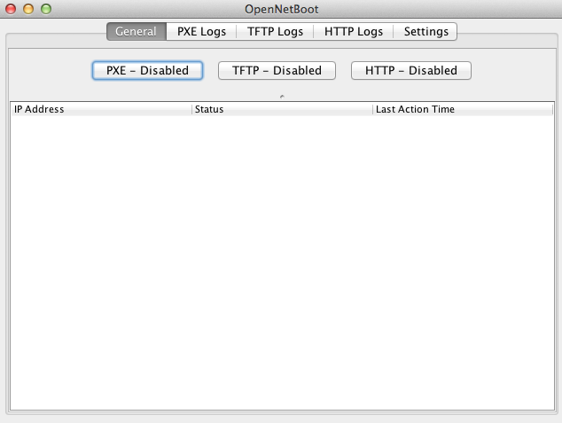
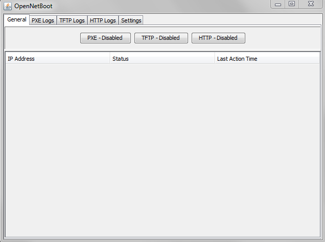
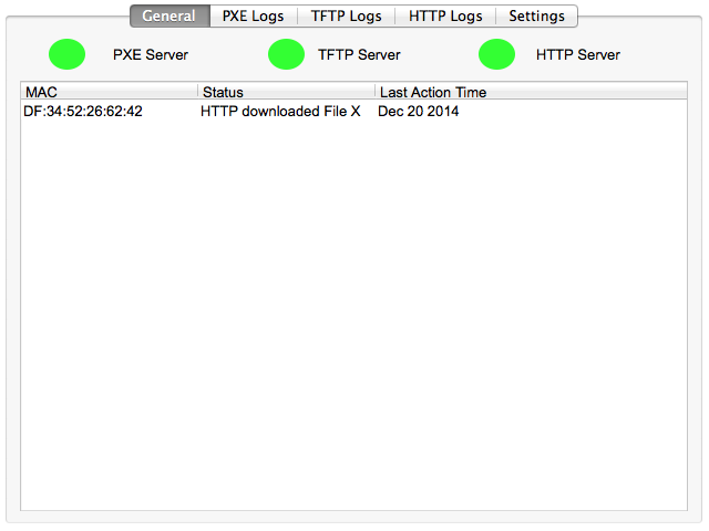
UI Design
The app went through several designs and mock-ups. Not altering too much until it became a web platform.
I also tried making different logos. This is before generative AI, I had to sit there in Gimp or Inkscape myself and draw ideas. Here are a few for fun.


Wrapping Up
I have maintained this app for over a decade now. It ran the heart of our server shipments for years, shipping thousands of servers. It helped launch my career. And gave me a love of lower level programming down to RFC. I am excited to share it with the world, and I hope it helps a sysadmin out there to boot systems. The system is Apache 2.0 licensed, and I am always happy to get pull requests or feedback!