Creating a Radio Part 2 – Arduino & Wiring

This is article 2 of the series on building a Radio. A key part of the project is the interface; I wanted to keep 100% of the original radios look and feel; that meant somehow I needed to use the knobs in the front along with the spinning the dial. The solution I came up with was to use an Arduino microcontroller, more specifically the Arduino Uno, to handle all the hardware interactions. This article will look at how it was hooked up, along with the code used for it. For the purposes of this article I will not go into too much detail about the parts, and allow the reader to research where needed.

In total there are 5 “devices” hooked up to the Arduino, the first three of these were the knobs. The volume knob, an original knob that came with the unit, feeds the Arduino a number, 0-1023 using a 5 Volt line, then that was mapped to a number between 0-100 to make life easy. The leftmost knob goes between AM/FM/AMC, and on my unit I could never get a stable reading out of it to feed the Arduino, so this knob is actually disabled on my final product. I could have replaced that knob with another, but I felt the project was great without that, along with it would have added a lot of work and stations to make. The center knob is a 10kΩ potentiometer I bought from makershed.com, they seemed to have a size that fit well; I had to drill down the inside of the plastic knob, but that’s how these things go. The two wires I got from the potentiometers each went into their own analog pin, I used 5 for the volume knob and 2 for the station, but this is completely arbitrary.

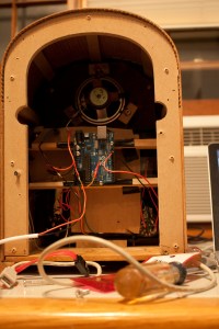
At this point I should mention that devices like the servo came with a little header on their wires. I took that piece on, and soldered a good wired onto the end to put in the Arduino. The wire the servo came with was thin and didn’t go in a pin well. Moreover all the parts needed power, so I got a tiny bread board from THE SHACK, took over one two row part of it that had double sided tape and put it in the radio. Then whenever I needed 5 volts, I could just use another pin in the bread board. You can see this in the photo below.

The next device to hook into the microcontroller was the servo, now as I said in the last article where I went over me tearing parts out of the original unit; the station knob was done with a string and a sensor and awfulness. Thus, I am using a servo instead; the code gets the input from the station knob, and then adjusts the servo to that mapped value. I got a HexTronik HXT900 Micro Servo 9g/1.6kg off Amazon for cheap; it works well, is tiny, and did everything the project needed; yet, it is fairly loud, so if that is important to you (when the station changes you hear it) then you may want another one. I put the servo in Pin 9 on my Arduino.

The last little device that was hooked up just for fun was a little yellow LED; my radio had a burnt out bulb next to the dial, so I replaced that with a LED. The 13 pin on the Arduino Uno already has a resister on it for a LED so I just put it in there.

The code is fairly simple and straight forward, it reads all the knobs, adjusts the dial when needed, and then sends all its readings over USB to the PC doing the music playback. The baud rate is set for 9600. The one little problem the Arduino code gave me that I didn’t foresee was I needed a set “packet” length to go to the pc, thus when the PC reads the line it knows if it got the whole data set or not reliably. To do this I have a set pattern that the data is fit into. It goes | then whatever the volume is | channel number | and then enough dashes to fill up 10 characters. So an example could be |100|5|— . I thought it was a fun and interesting little quirk.

The system waits 200ms, to let the values change and stabilize if they want, then does it all again. I am used to desktop programming where 100% CPU is bad, so I treated this similarly by habit, but you could speed it up if you wanted. The code is going to be in here to follow (its pde, but rename to TXT works too), along with a picture of the wiring (though some wiring may have changed in final product, old picture).

One part I have yet to mention that is a critical component is the speaker, I used the speaker that came with the unit. I cut the wire from the original circuit, then got a 3.5mm stereo jack from THE SHACK and soldered the wires onto that after making sure that I got positive and negative in the write positions. I can’t guarantee this will work with all radios but that plug was able to go right into a USB audio card I used.

Feel free to email or post with questions. The next part will be the PC and the software running all of this.


https://github.com/daberkow/RadioManager/blob/master/radio_controller.pde
Creating a Radio Part 1 – General Hardware

The project I have been working on for the last two months was a radio for my parents anniversary; but not a normal radio, I got a replica of a 1934 Thomas Radio (Collector’s Edition), gutted it, then built my own system to put music on. I figured for fun I will write a few posts about it, and anyone who wanted to try to reproduce it again would have ample data.

Radio Picture

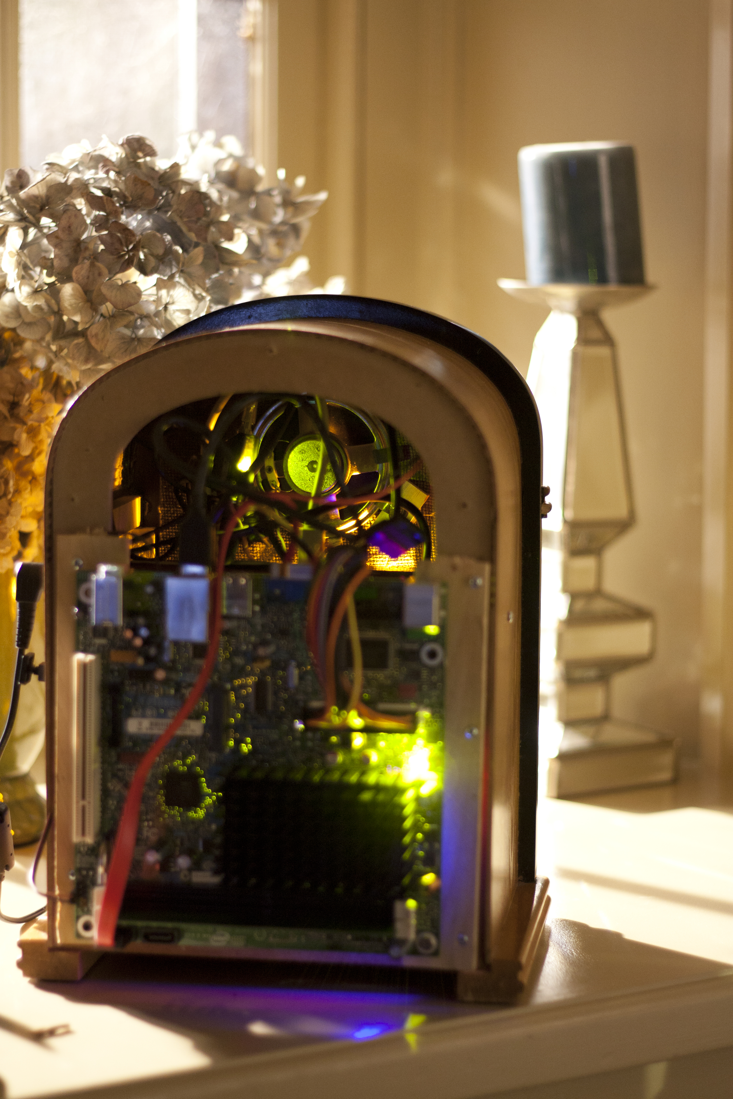
This is the front of the final radio

To start let us look at the model radio I started with, most will work, just with varying degrees of work put into them. The closet website I can find to the version I have is here, http://tweakeddesigns.blogspot.com/2011/07/reproduction-of-1934-thomas-radio.html. I think this is the exact radio, but with a slightly different wood stain on it. First I got that radio, then ripped all the parts out of it, except for the two outer front knobs (potentiometers). It turned out that the middle knob was just a stick with a string around it that went to a sensor and the channel dial. So the whole dial moved then this string was twisted, but that was only held up by the old internal electronics. Since that was a very… janky, I removed that, and replaced it with a separate potentiometer and a servo to change the dial hands. I made a awesomely horrible 3D render of how this looked, with all the original parts removed, and a servo added. I will do another post all about the Arduino and how that was hooked up.

3D back of radio

Here is a bad 3d model of the empty radio in the back

Now for the best of prototyping, I used cardboard to support all this, cardboard is your friend for prototyping, except when it catches on fire, then it’s bad. Afterwards, I got these wooden splints from Home Depot, and put them in to reinforce everything, they came in about 14 inches long by 1.5 inches wide by 1/8 inch thick. I secured them with super glue, then screwed the Arduino microcontroller into these supports. Of course with plenty of electrical tape over the wood to shield it all.

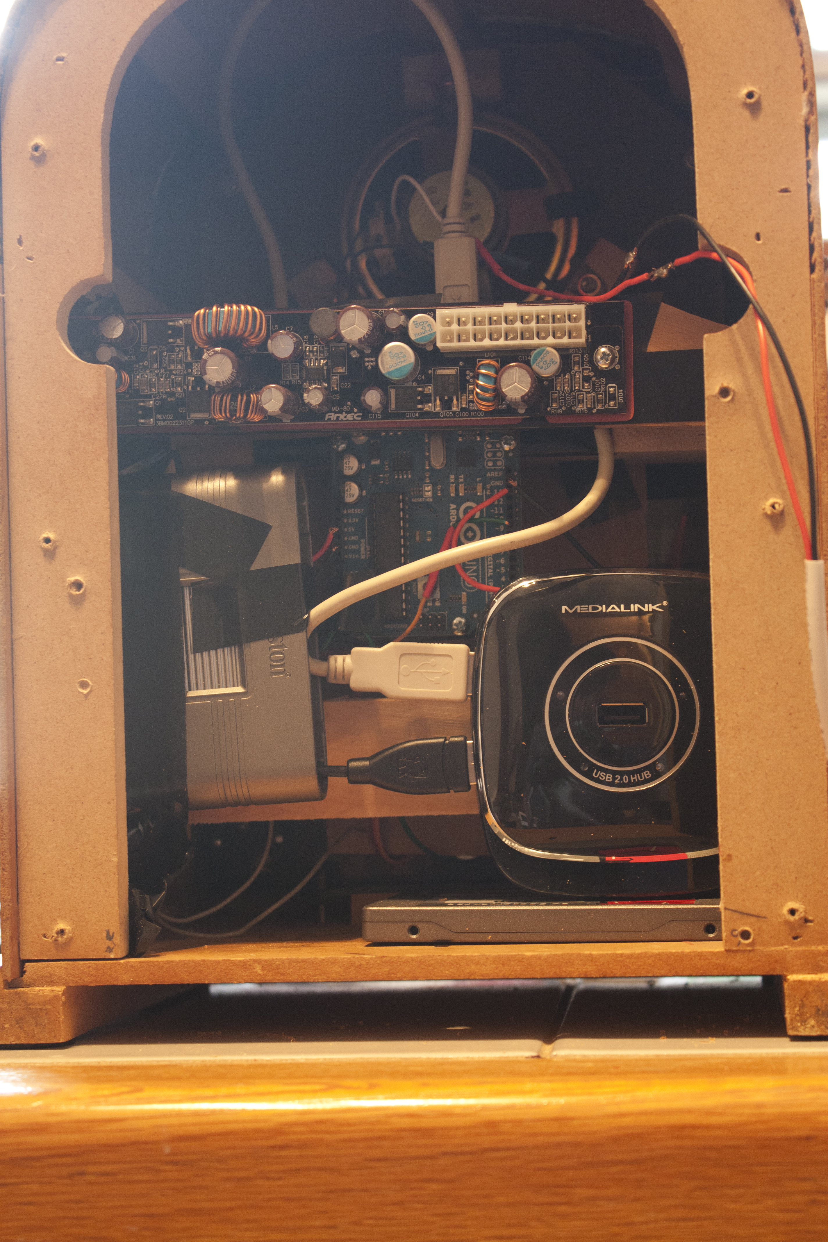
One key part of the system is how the music is played. The music is played through a Mini-ITX board that is attached on the back. I needed a power supply for this, so I got a Mini-ITX  case(Antec Mini-ITX Case ISK100) and just removed the power parts. The original plan was to put the pc outside this device, in a normal pc case, but I figured I’d just go for this design. Then I drilled a hole in the side so that I could use the Antec cases external power brick, and just plug it in the side. That had plenty of electrical tape on its supporting splint, along with a plastic shield that the power supply part had under it in the Antec case. I don’t like fire, so I was sure to be careful when handling these power systems; also, this was the only splint that was secured with screws and super glue, I dont want a charged power supply falling. The picture below shows this.

Back of radio

Real radio back

In a simple wiring diagram, we have the Arduino all wired up, post to follow, that goes into the mini-itx board through a USB hub. The USB hub also has a SD card reader, the software and Ardunio goes into the USB hub to make everything easier. The SD card reader is aligned to the side port, where the tape drive used to be, then songs can be updated by taking SD card out and updating the files. Then we have the original speaker in the radio wired into a 3.5mm headphone jack, available at Radio Shack, I’m sorry THE SHACK, and that goes into the audio on jack of the mini-itx board. The power supply cable goes into the Mini-ITX board, along with the SATA SSD. I know that doesn’t explain it well, but I will be writing more articles, one about the wiring and the Arduino wiring; then another about the software running the Ardunio and on the Mini-ITX board.

I’m not great with technical documents, if anyone has any questions feel free to email or even better post a comment.

Coming Up Soon…

I have been working on a secret project for my parents anniversary for the past few months. Now that it is complete I will be posting about it and the steps I took to make it ( I think some people may be interested in it), as well as start uploading the the code of some of my discontinued products for people to look at. Yet before all this can happen, I must move across the country; so it may take a little while for the material to go up. Stay tuned.

6to4 Adapter Cleaner, v1.60

This version brings a few fixes and new features, hence the version jump. Features Include:

  • Minimize to Tray when removal is working
  • Checks if already running on startup
  • Faster IPv6 detection for method 2
  • Slightly smaller


Download:

https://github.com/daberkow/daberkow.github.io/tree/master/6to4CardCleaner

CUFU v1.00

Here is my latest little creation, CUFU, which stands for COM USB Finder Utility. The purpose is if you have to plug in and out a USB to COM port cable a lot and it changes which COM it is in windows, making you go to device manager, now you can run this, and hit the icon, and bam it will tell you. Right now it will tell you by default if “Prolific USB-to-Serial Comm Port” is plugged in, and which is the most recent. That can be changed, there is a updater. Its a standard one week project. Also I wanted art for the about page, “art” is stretching it for what I made.


Download (Requires .Net v2)

https://github.com/daberkow/daberkow.github.io/tree/master/CUFU

Update

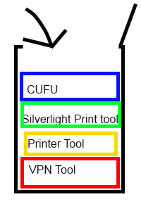
Quick update, I am working on a program that finds what COM port a USB <-> COM cable gets when it is plugged in, I am taking a class that makes me use these cables a lot. My programing tends to be a sort of stack, whatever I think of most recently gets on the top and worked on. I am also working on Print Manager 1.0 which will be a Silverlight app, hopefully.

My thoughts system

Dan Brain Stack

Update

I am currently working on my A+ certification. As for the way of software, I am working on a new printer manager, mostly because my schools way of printing is horrible. I also have an idea to make a tool to fix a iTunes library, as in find missing files without going to each file. Finding duplicates, fixing artists names where there is a ‘ making all the songs split between “two artists”. Maybe converting a zune library to itunes and vice versa. I will look at taking files off a iPod touch/iPhone, but no promises.

6to4 Card Cleaner v1.50, IPv6Activator v1.00

This new version of 6to4 Card Cleaner adds the full Microsoft process of fixing the problem; the program will disable IPv6, remove the cards, and then run KB980486. There still is a option to just remove the cards.  Added features also include an updater, a window that allows you to set IPv6 to any of the 6 settings, and a new backend.

These cards WILL NOT show up in device manager, unless you turn on hidden devices, and WILL NOT show up in ipconfig unless you do ipconfig /all.

I also took out the window that lets you change the IPv6 setting, and made it its own app, so if you need a user to just change IPv6 they can get this 70kb app.

As always any bugs please report them, I will patch and the automatic updater will alert users a new version is available. Source available on request.

Download

Main Program

https://github.com/daberkow/daberkow.github.io/tree/master/6to4CardCleaner

IPv6Activator

https://github.com/daberkow/daberkow.github.io/tree/master/IPv6Activator