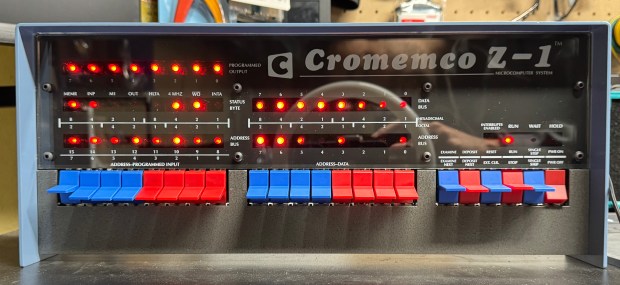
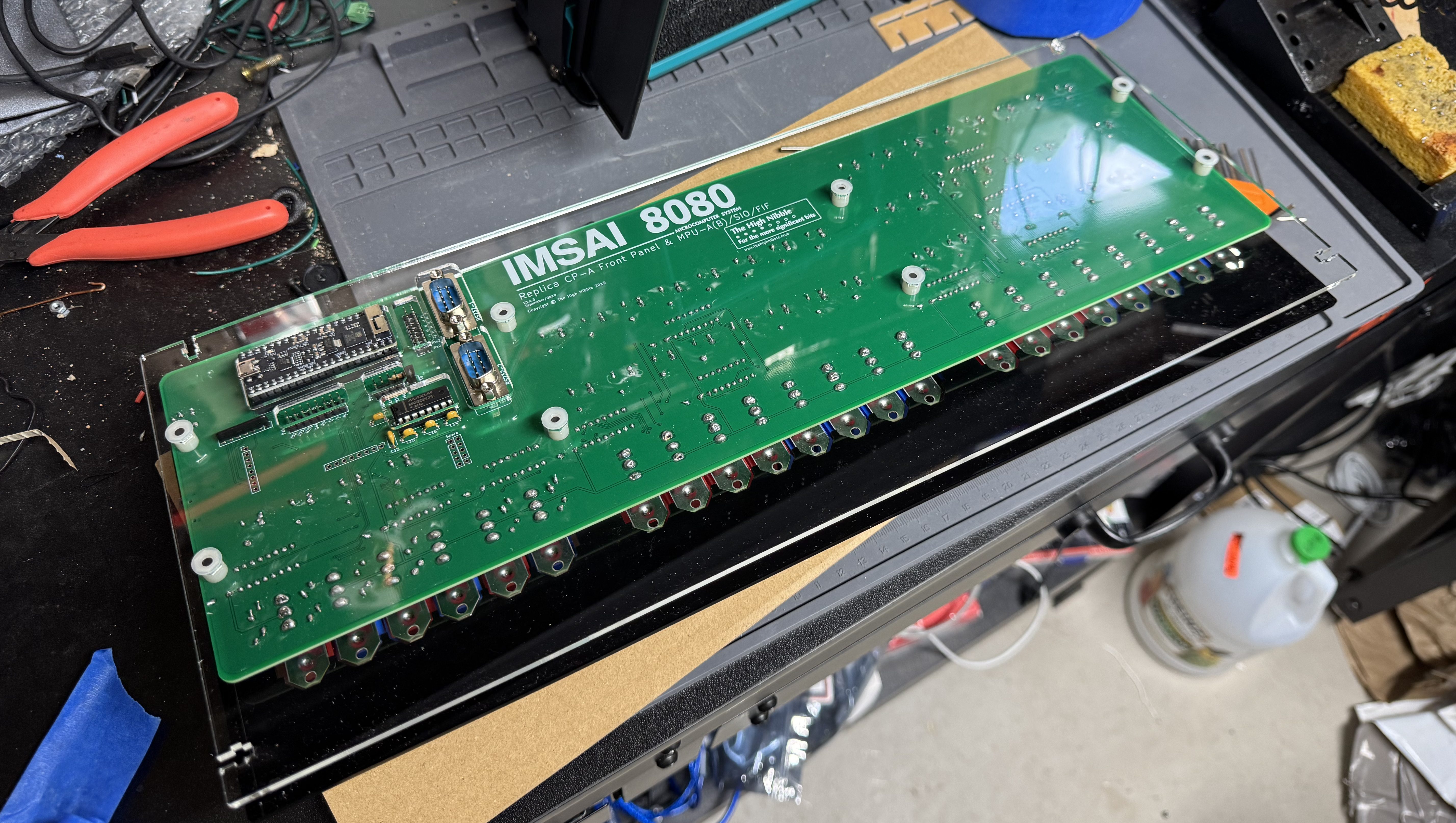
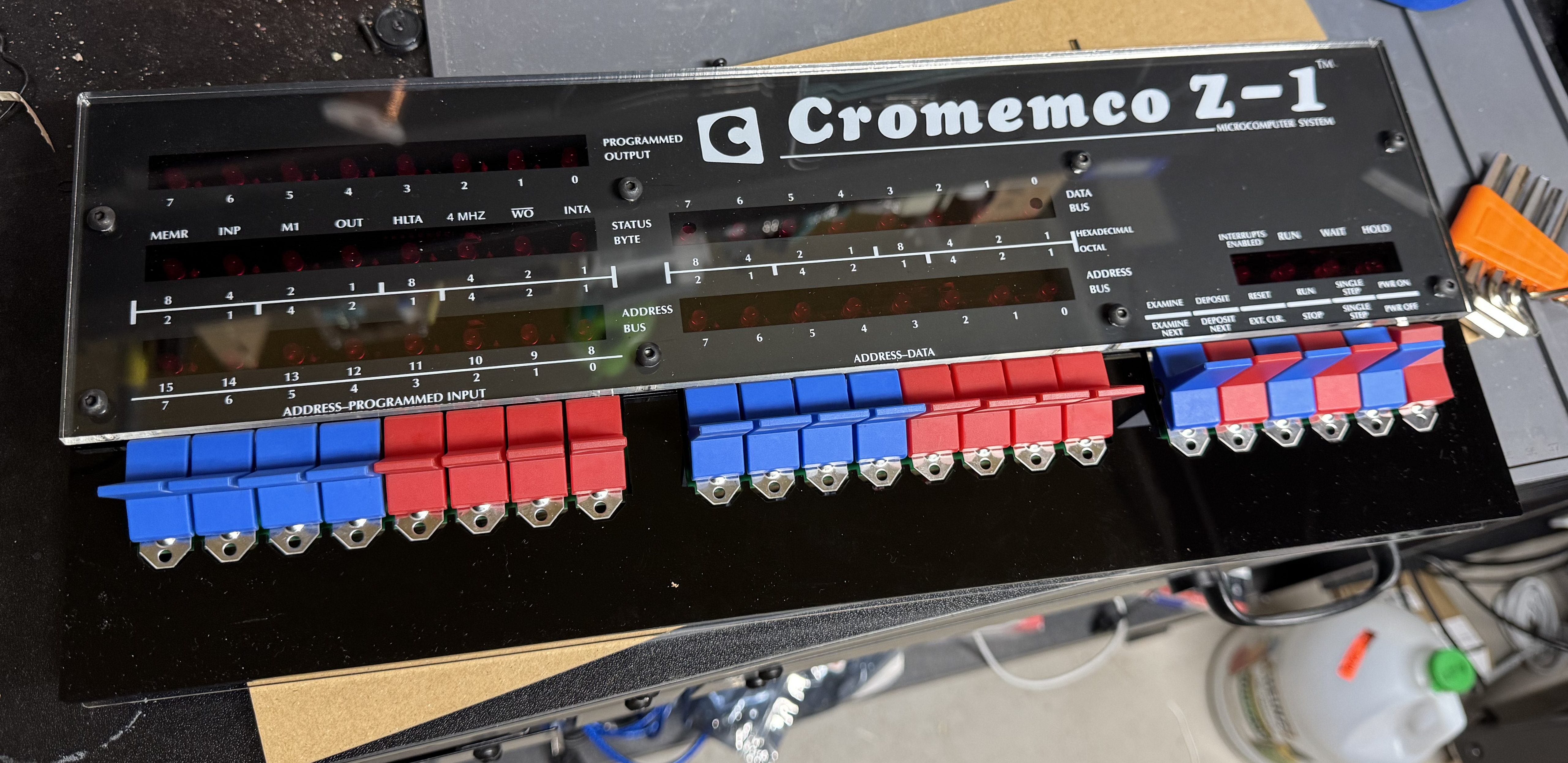
The High Nibble is back with another fun retro computer kit. This one of the Cromemco Z-1. I reached out to the creator of the kit when it first went up, and he asked if I was sure I was interested. The kit is 99% the same as the IMSAI 8080, including most of the components except the acrylic panel and new firmware. The kits are so similar the PCB for the main board is the IMSAI 8080. I enjoyed the last one so much and wanted to support the creator (not to mention a new kit means more blinky lights on the shelf); thus, I ordered the new kit.
The kits are not cheap at $300, but come with everything you need, including a ready to go controller. The packaging is done well with individually slotted spots for each switch and IC in cardboard. The metal case is a nice touch. And just like before, the firmware is fantastic. You get a full web interface, external serial ports, the gorgeous front panel, and the system can update over the air update via Wi-Fi.
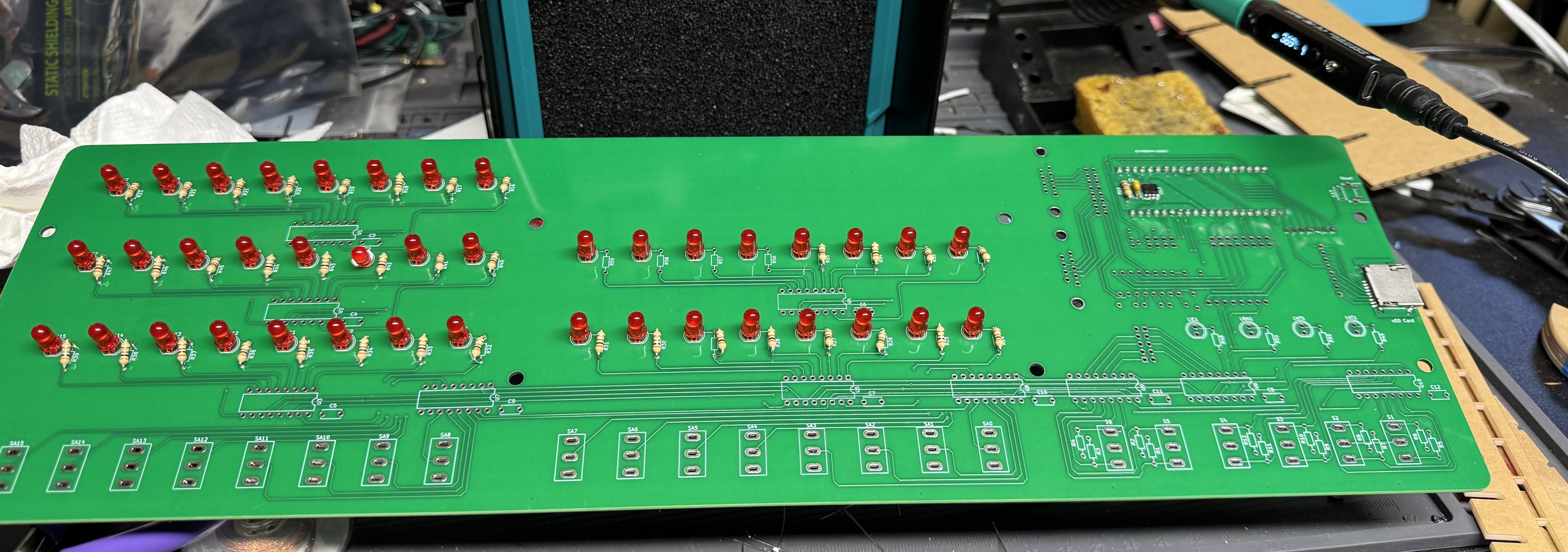
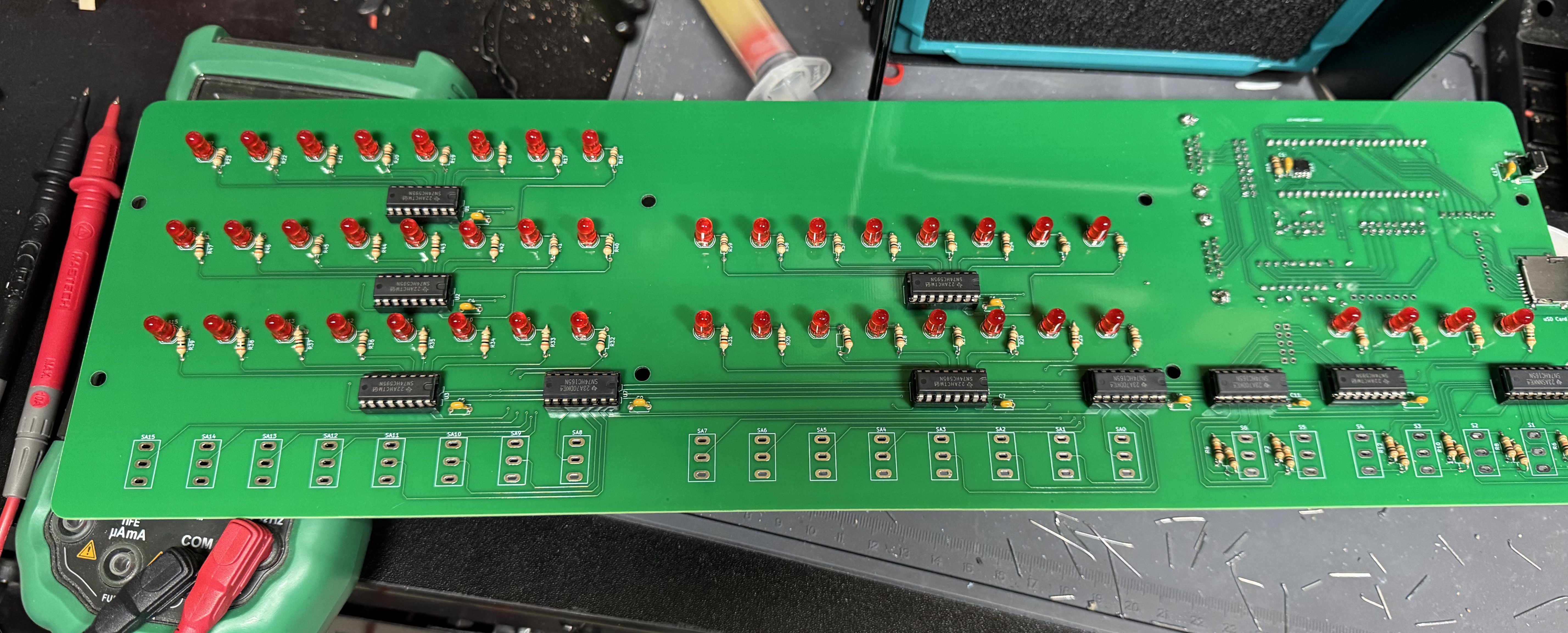
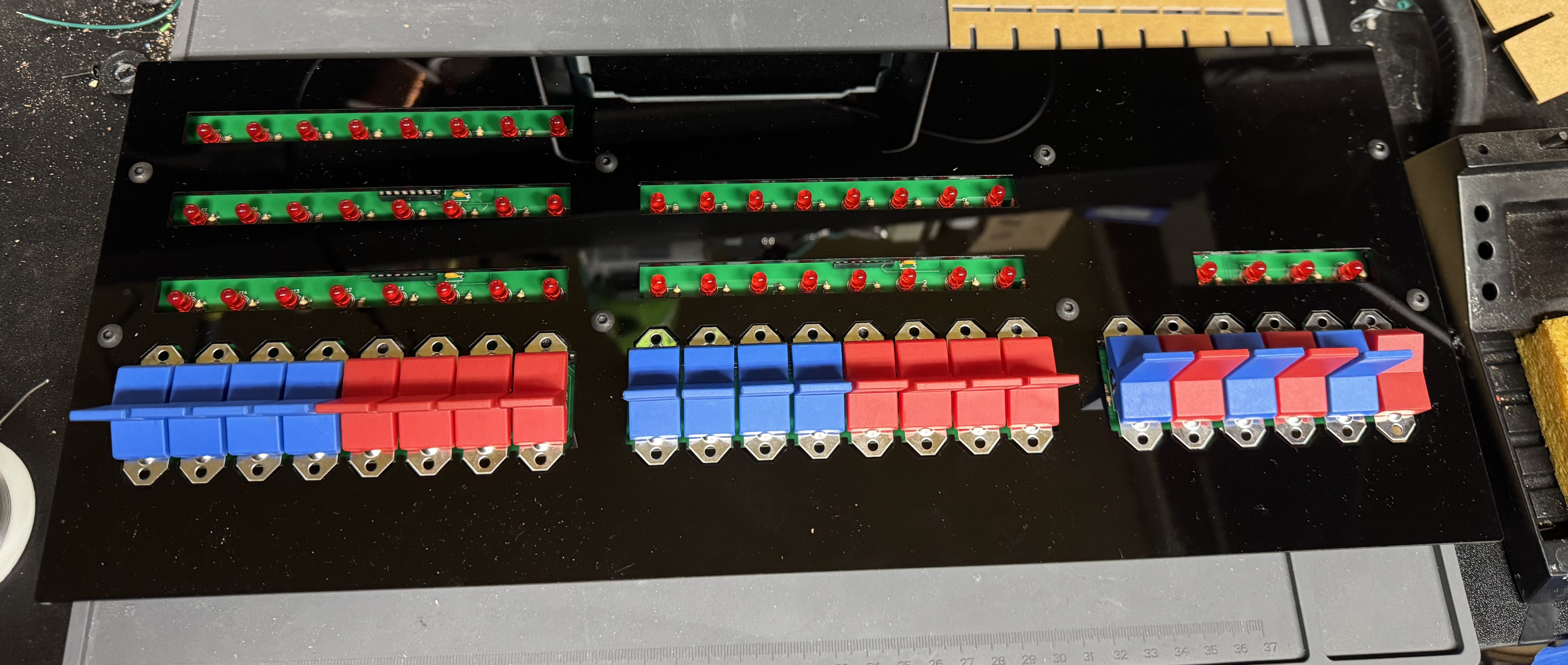
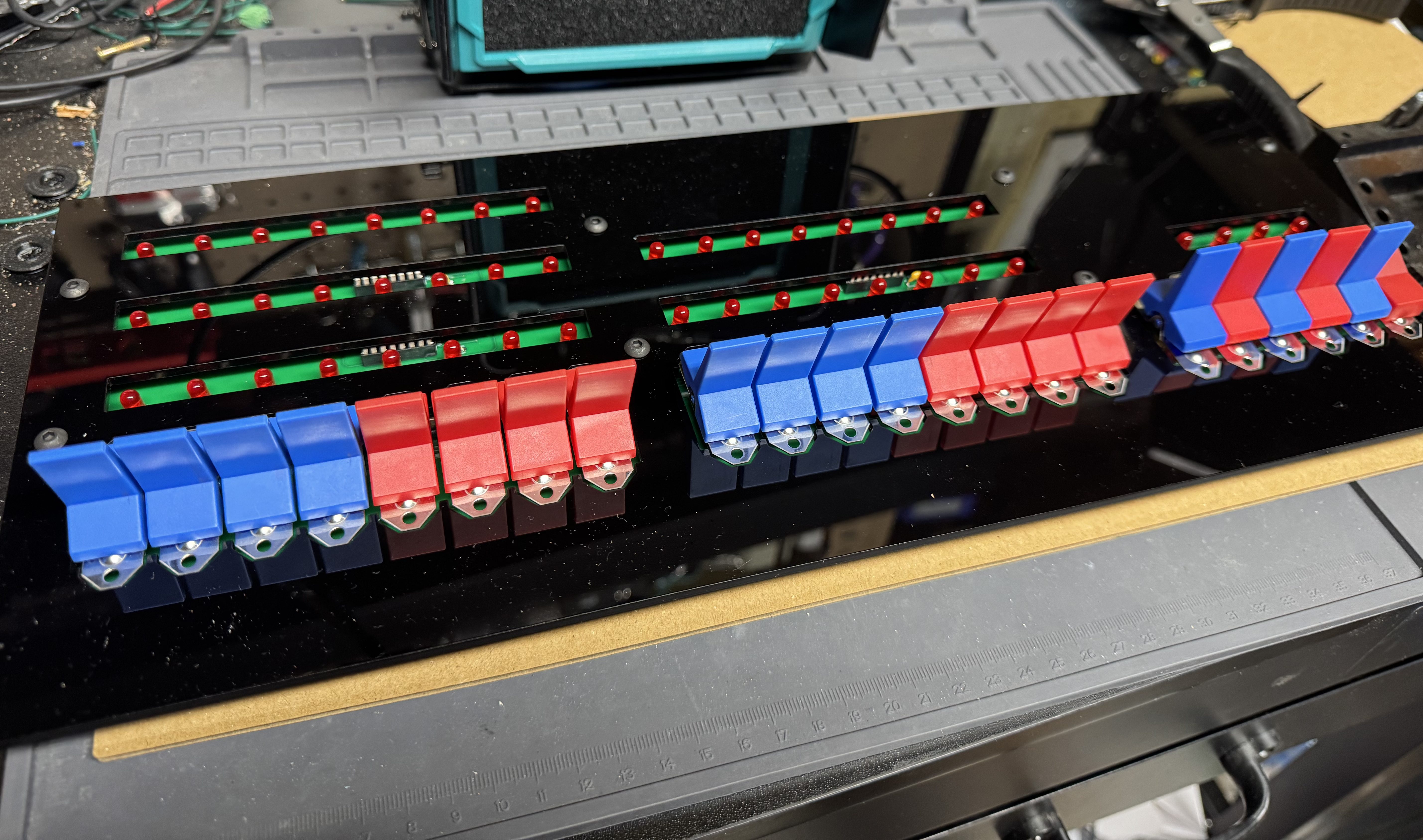
I won’t go too in-depth about the kit because it is so similar to the other one. The soldering is not too bad, the process starts with one small IC that has to be soldered in the front of the pcb, after that things like sockets and LEDs are easy, large, and straight forward.
I got a new soldering iron, the Pinecil from Pine64. This was my first project using it and I found it delightful. It’s smaller than my old iron, making it easier to handle. It’s advertised as a “smart” soldering iron which means when you put it down in a holder it quickly cools when not in use. A very nice safety feature.
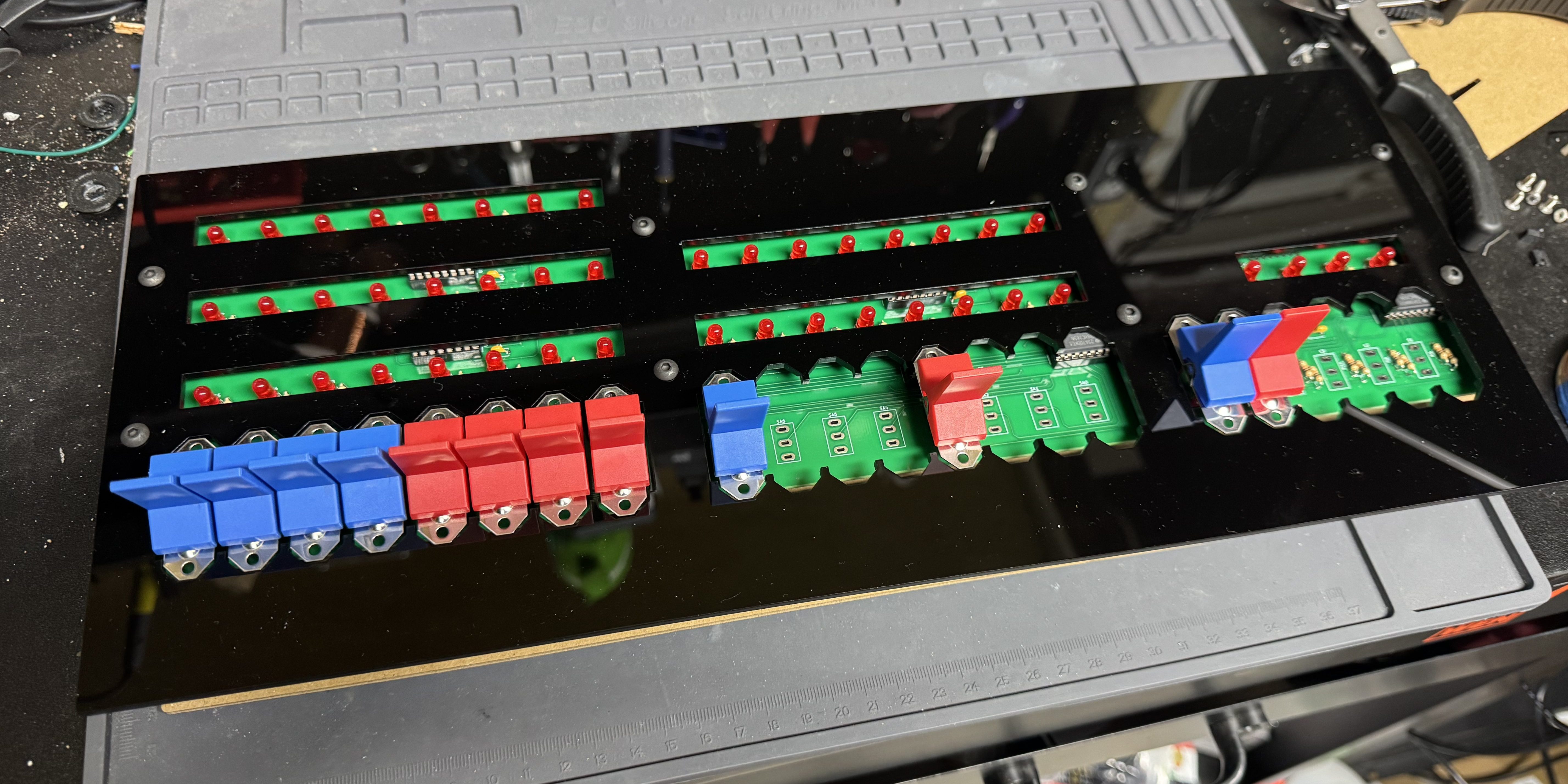
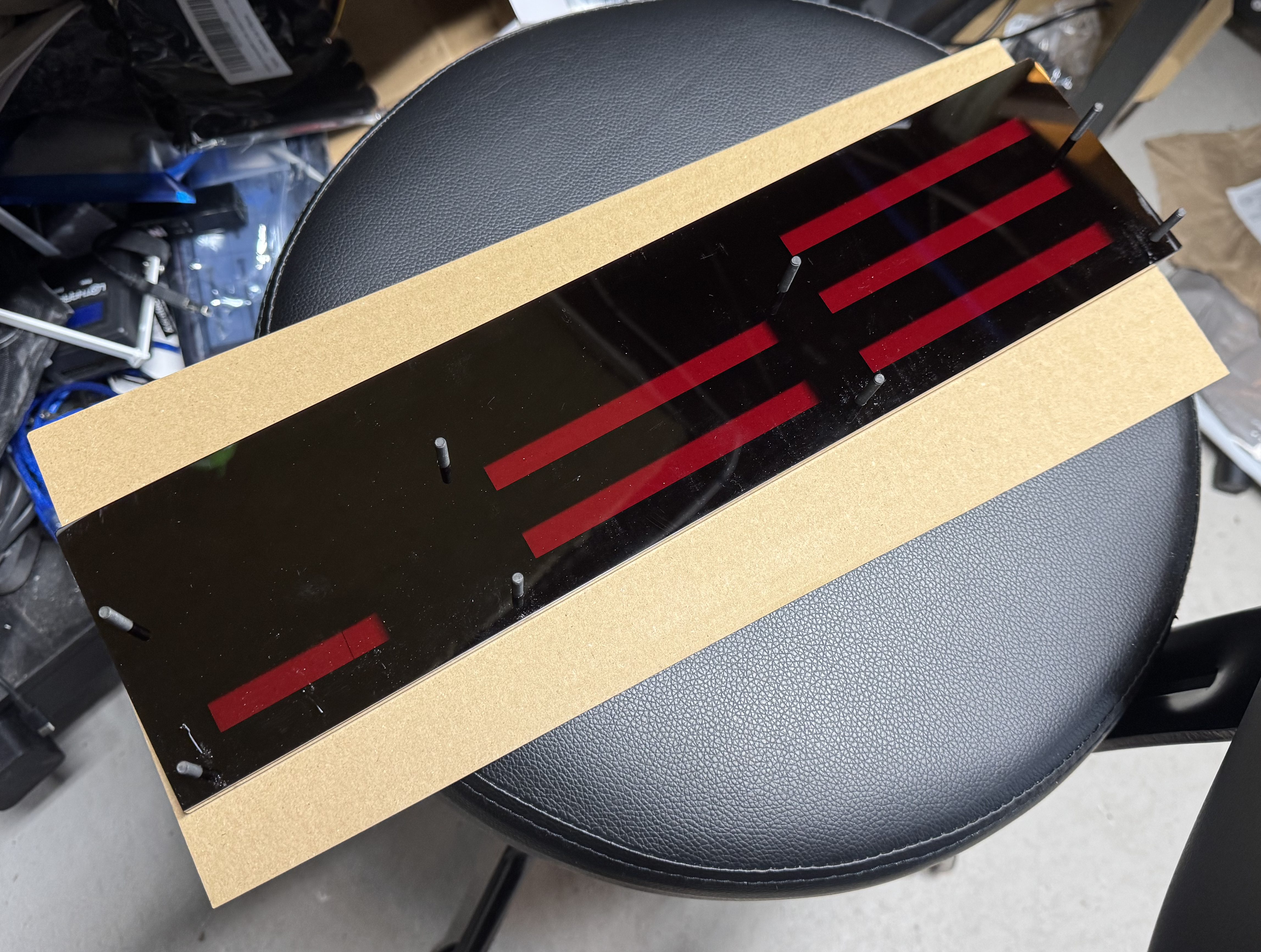
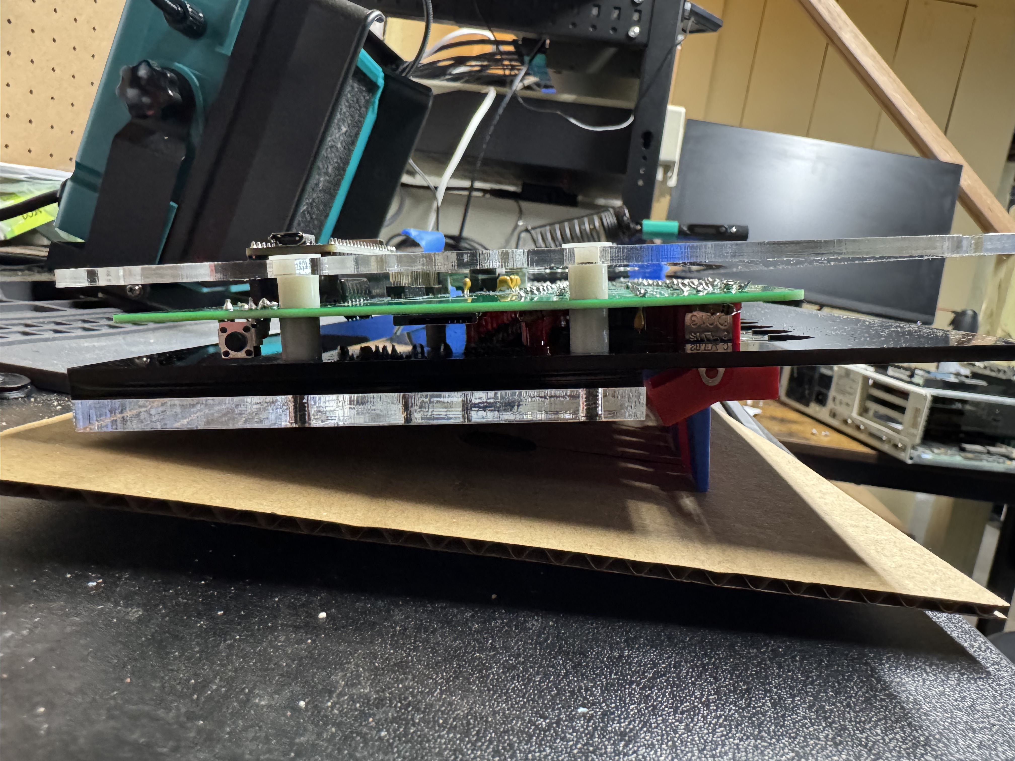
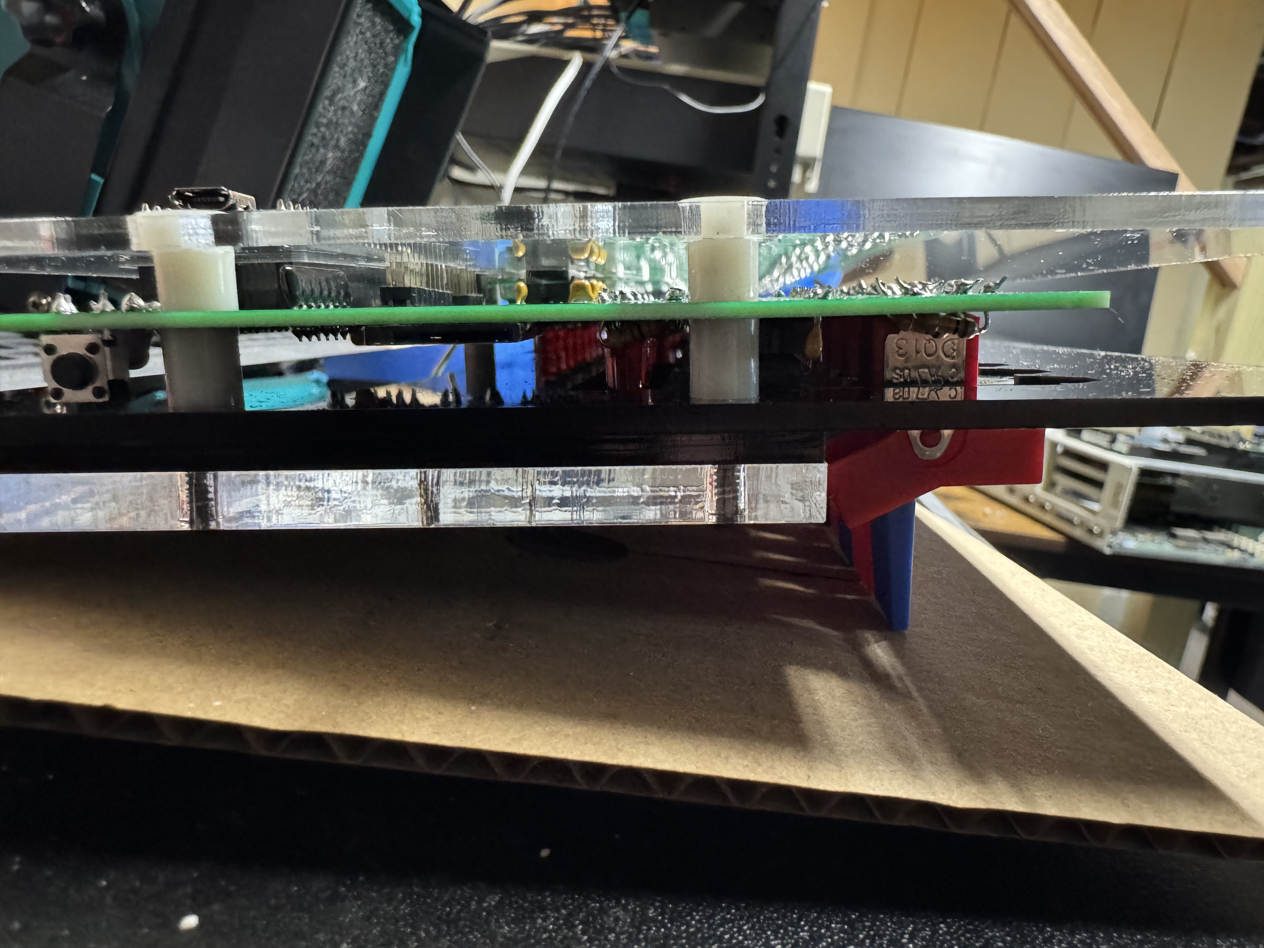
The parts of the last build that were difficult are here too, having to put the system together as a sandwich of acrylic and circuit boards it’s a bit tricky, but once you get it in the right spot tightens up easily. Tape helped keep the build aligned during assembly.
The website for the project has a lot of good information, https://thehighnibble.com/cromemcoZ1/. There’s also a helpful YouTube video, same one as the IMSAI kit, that walks through the construction step-by-step.
The main step that gave me an issue was when you get to Testing, the LS2 light would not come on. After looking in the forums, https://github.com/orgs/thehighnibble/discussions/120, turns out that is a difference in the firmware, and it is not supposed to come on. With the video being for the other kit, it is not mentioned.
Overall, another great kit, and another fun system to add to the collection!
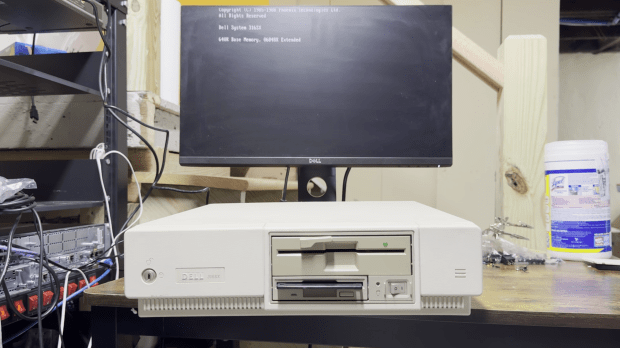
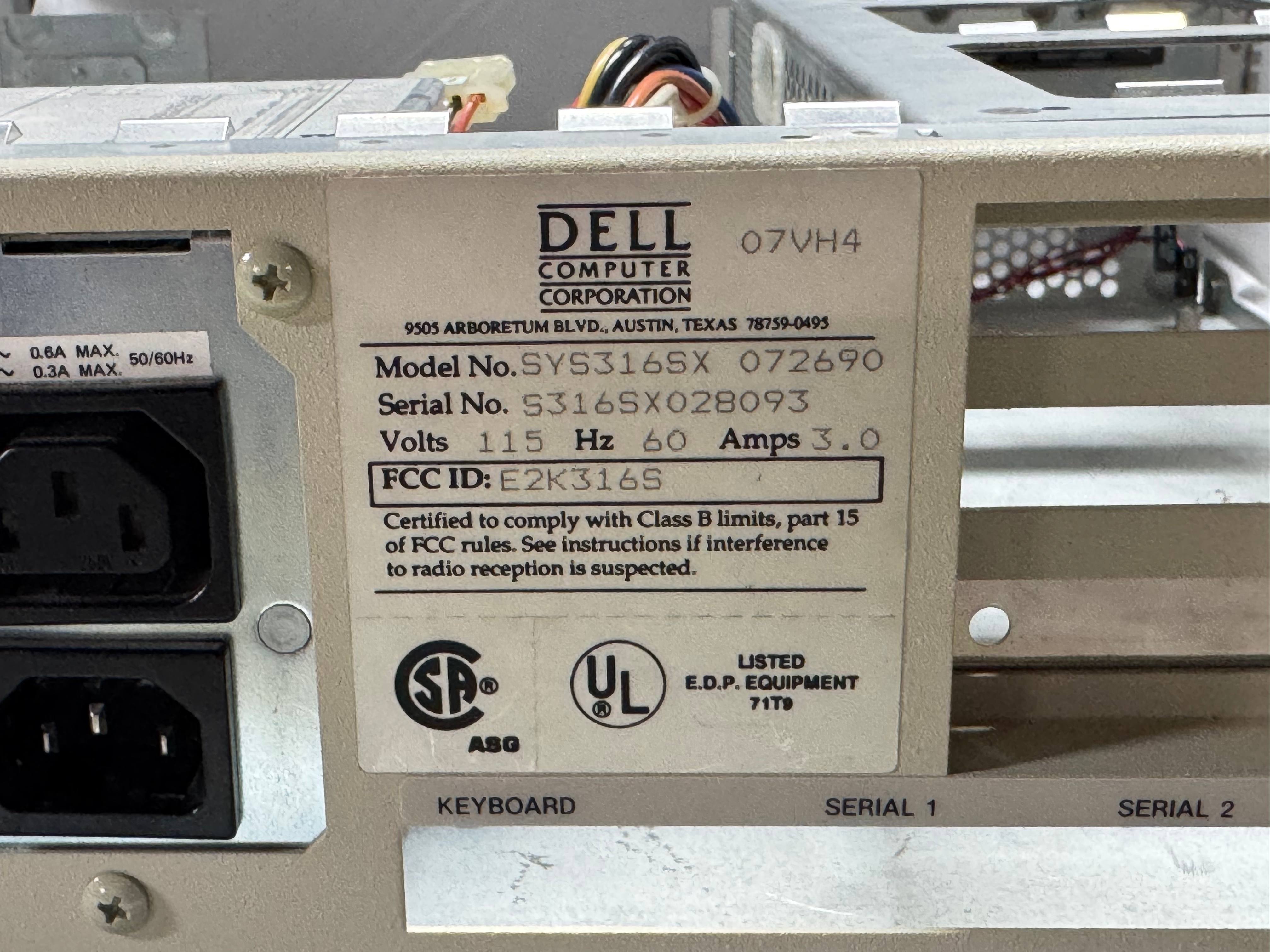
I recently got around to restoring a Dell 316SX—my first childhood computer. It’s a 386SX that lived in my parents’ attic for decades, and reviving it was a journey full of debugging, power supply replacing, and data recovery.
Early Memories
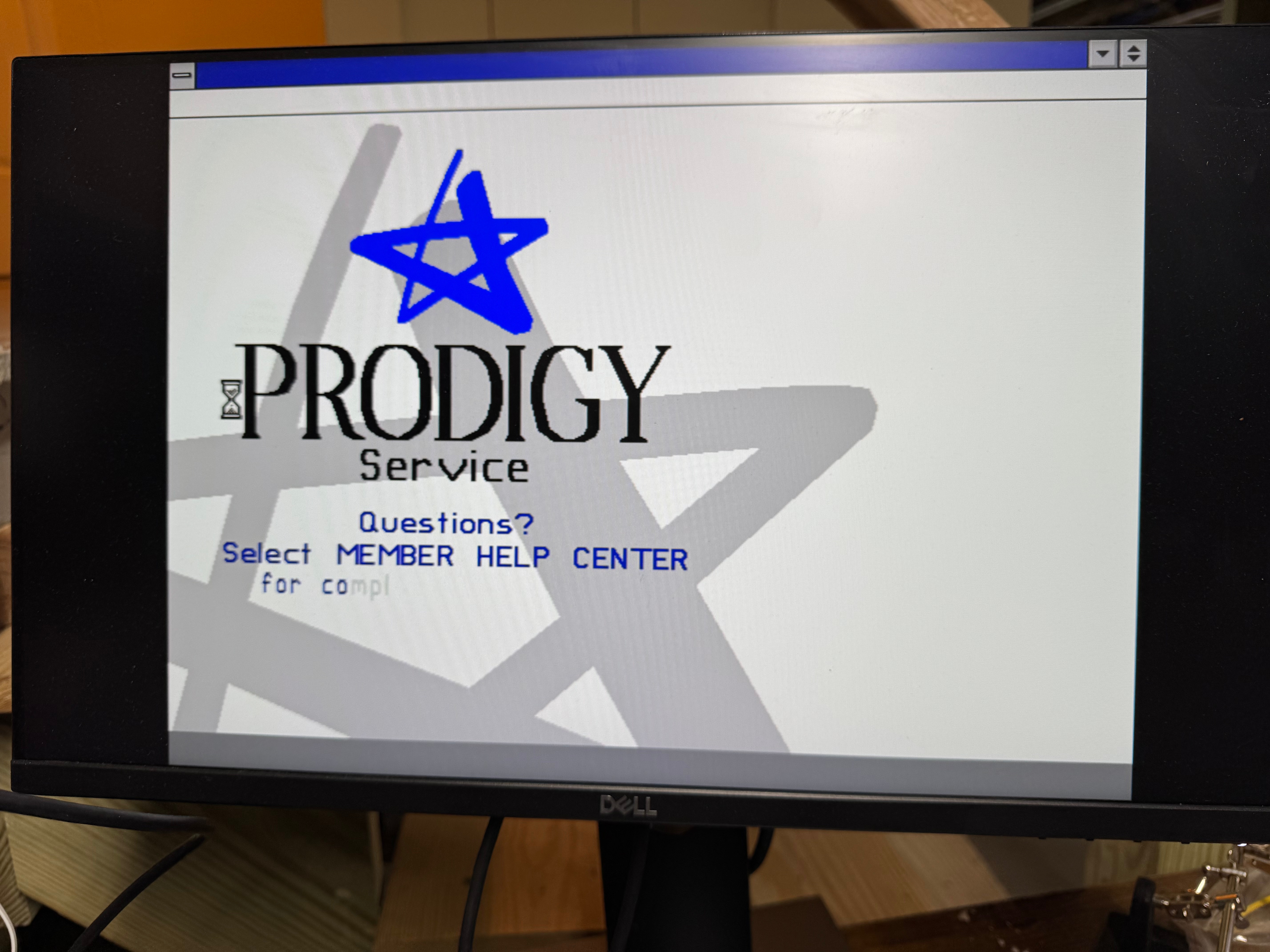
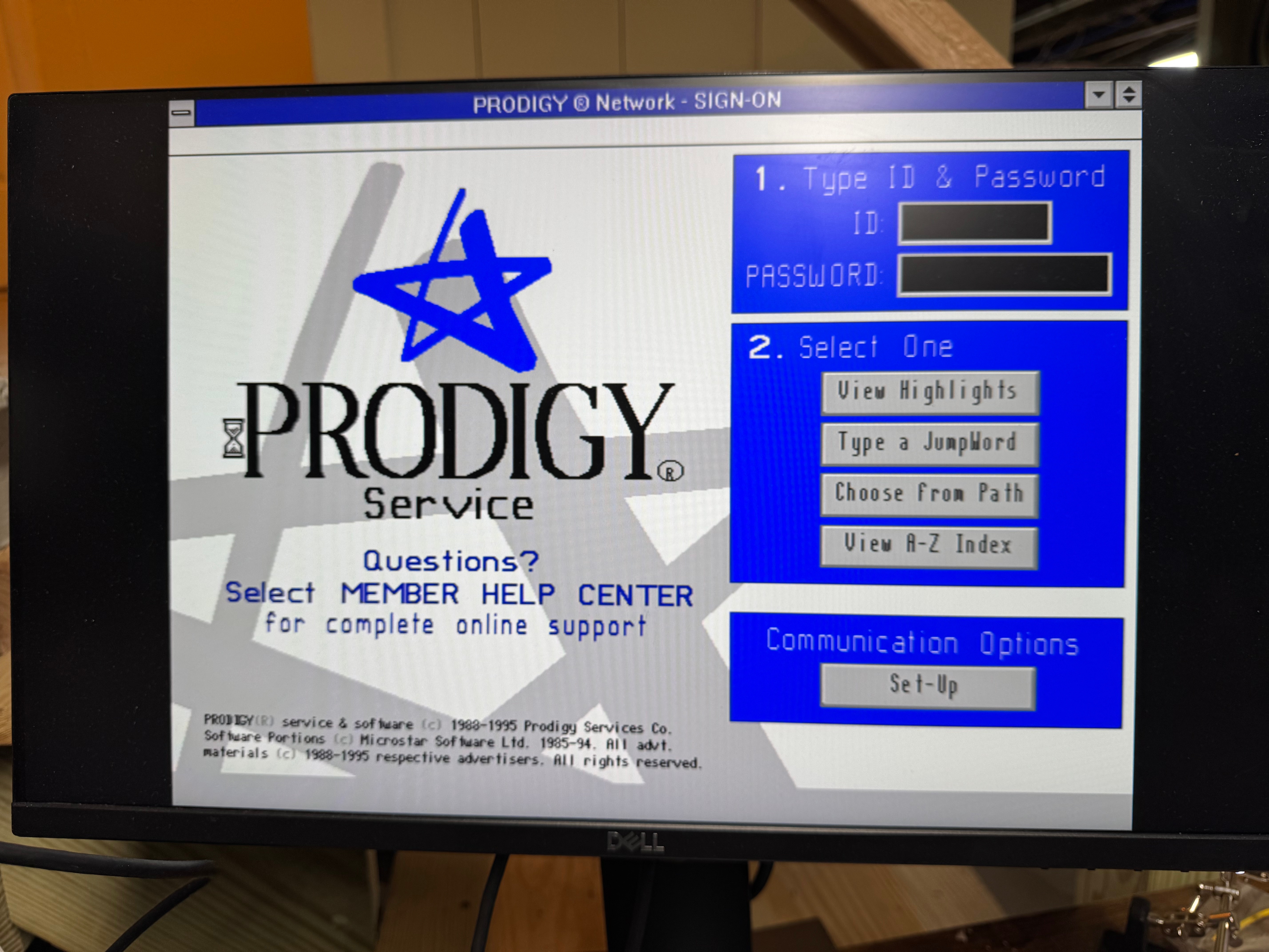
This computer was the first computer I had growing up: a Dell 316SX, with a Intel 386SX. I remember being little and playing Sesame Street games on Prodigy on a parallel port dial up modem (I need to see if I can find that). Shout out to the people trying to bring Prodigy back, https://www.vintagecomputing.com/index.php/archives/1063/bringing-prodigy-back-from-the-dead. There is a photo of my mother pregnant with me, playing the original Sim City on this computer. I always knew I had this computer in my parents attic, and one day I would need to get it out to play with it. Now that I have a bit more space to work on these projects, I got that system (and an old 486DX2 that someone gave me well past its prime) to play with.
More will come of the 486 on here, but that one got going pretty easily and is my go to machine since it has 5.25″ floppy, 3.5″ floppy, a CD-ROM drive, and its hard drive died so I gave it an SD card reader. That makes the 486 very useful; it also has a ton of ISA slots and is easy to work in.
I found a catalog with this computer in it! A PC World from 1990, page 27! I think the monitor is long gone, being a big heavy thing to store. I know my parents got it through a program at one of their work that discounted computers so people could work at home.
I am guessing this was the 40MB VGA Color Plus system. This one also has 4MB of ram, which would have been added on later.
Powering On
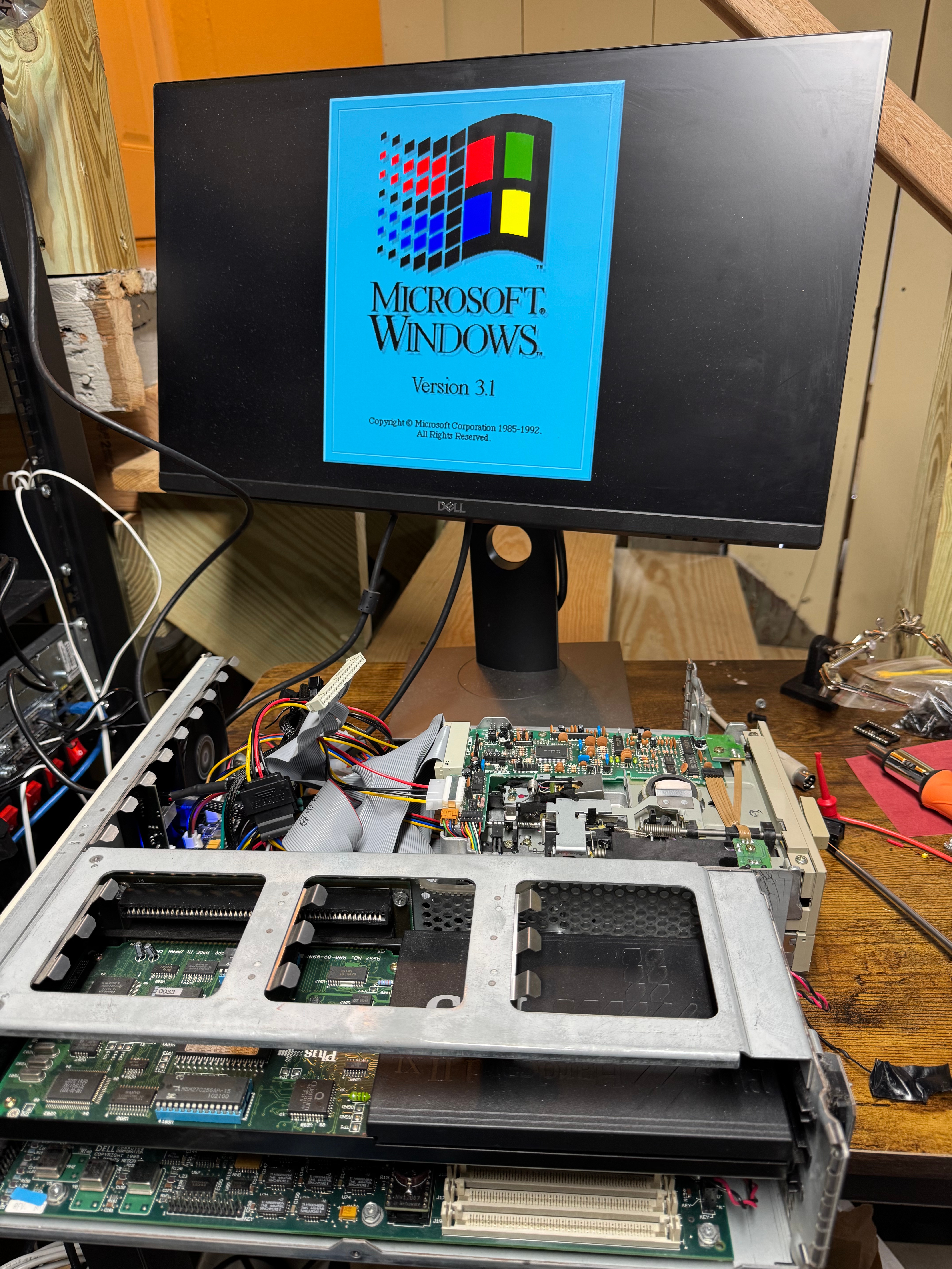
Anyway, back to the Dell 316SX. I could do the right thing and check all the capacitors and everything in the system; that’s what I should have done… So I turn the system on, and I get the familiar fan noise, and the 1990s smell. But no beep, no post, no nothing. The floppy drives don’t even attempt to seek. I left it for some time hoping that the capacitors would reform on their own, and come back. No luck.
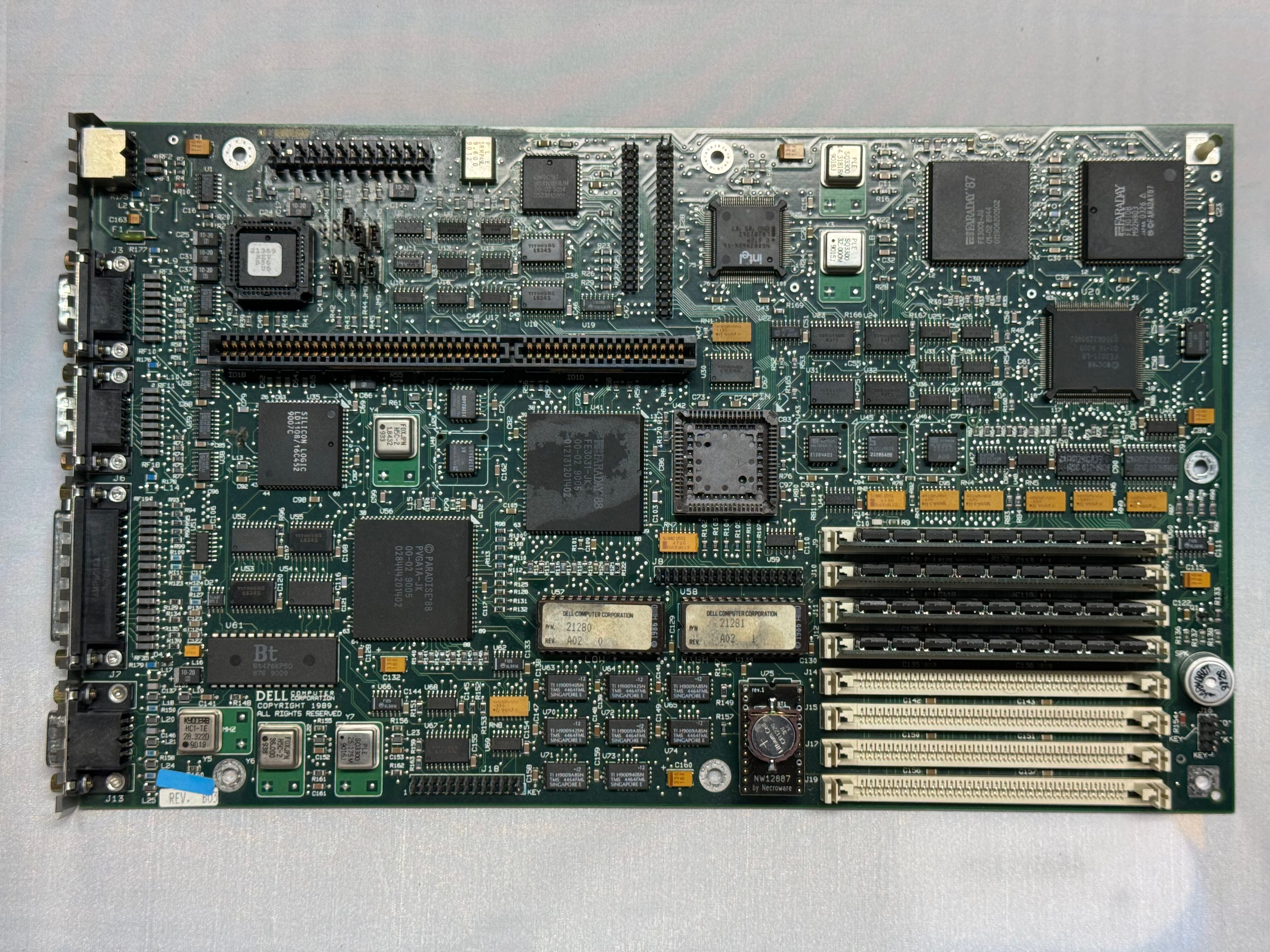
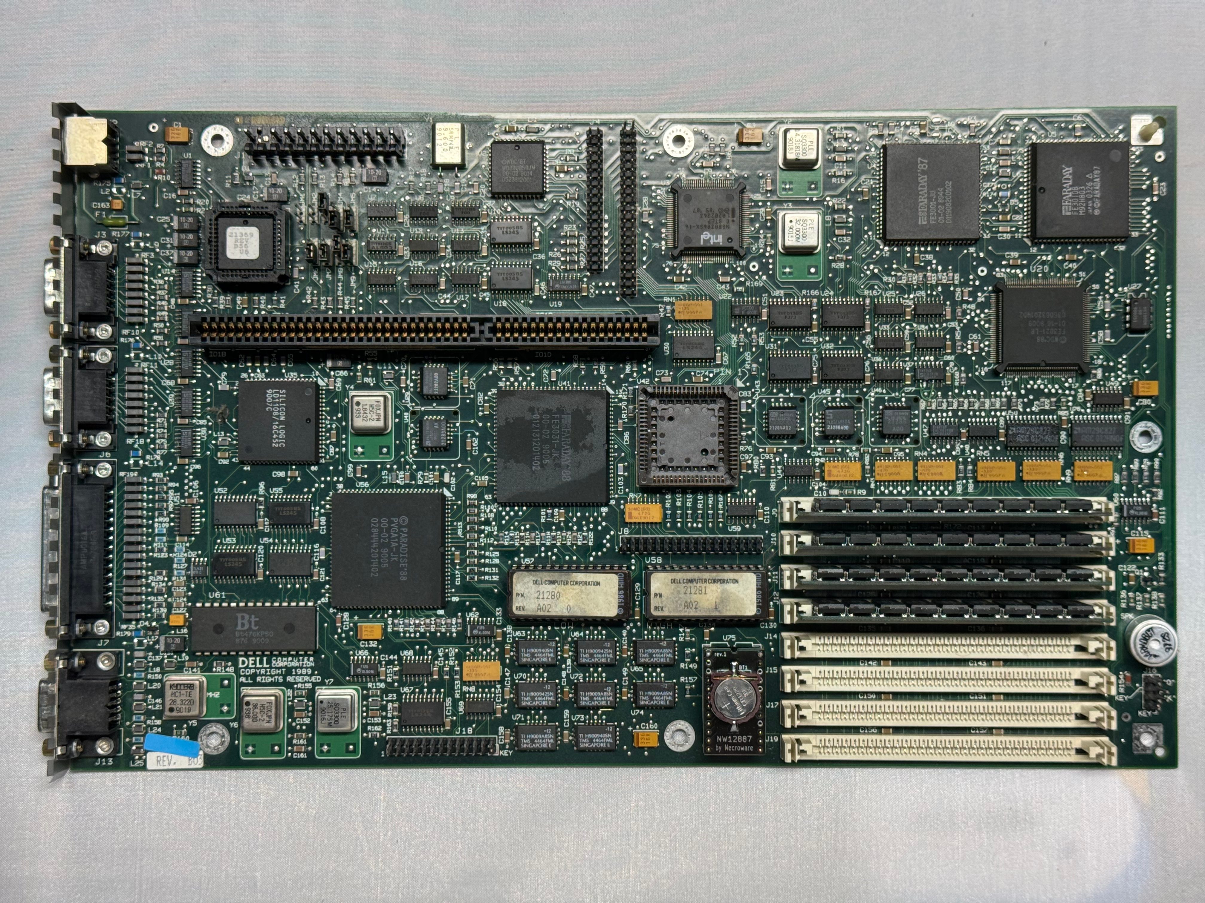
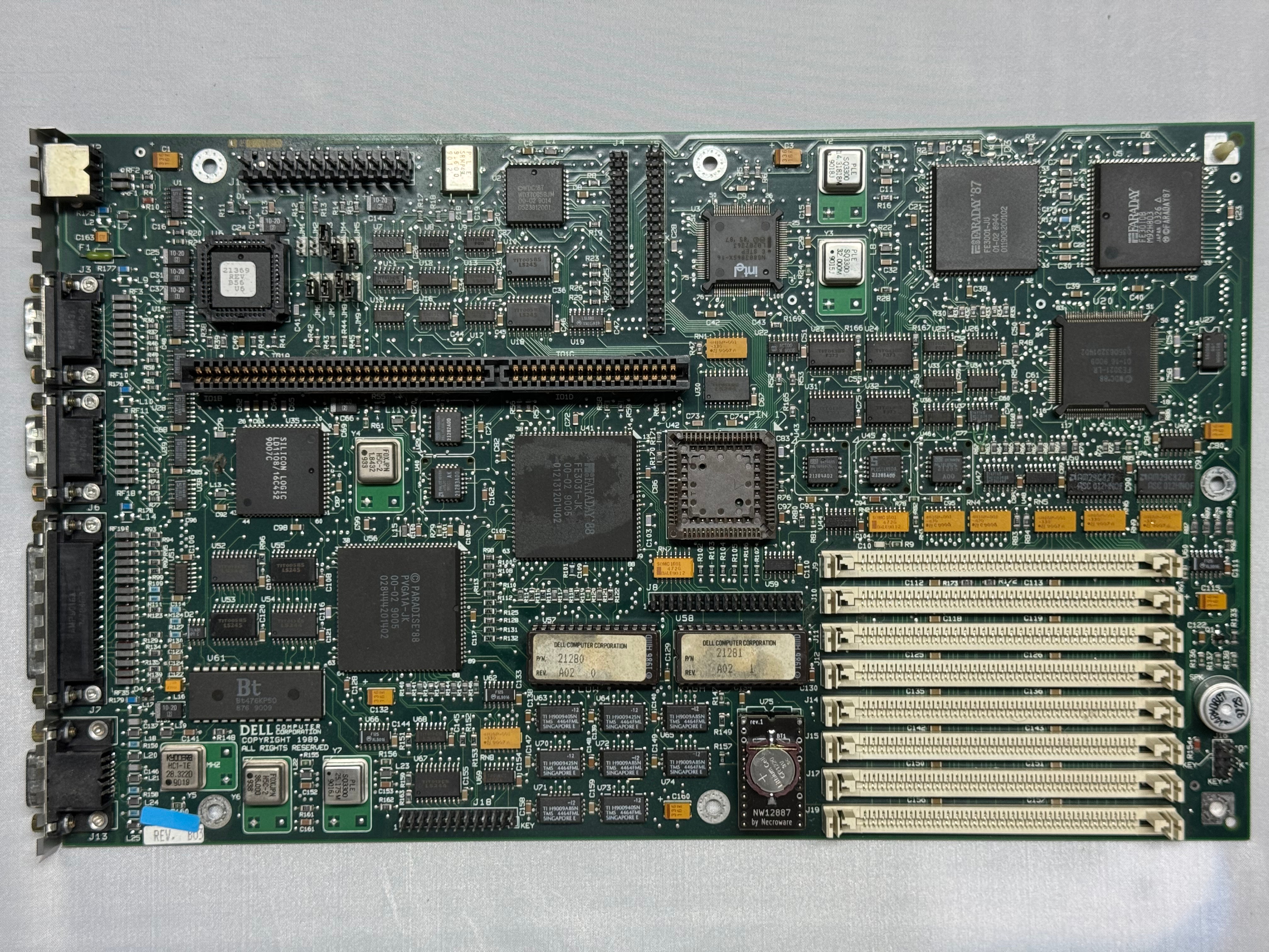
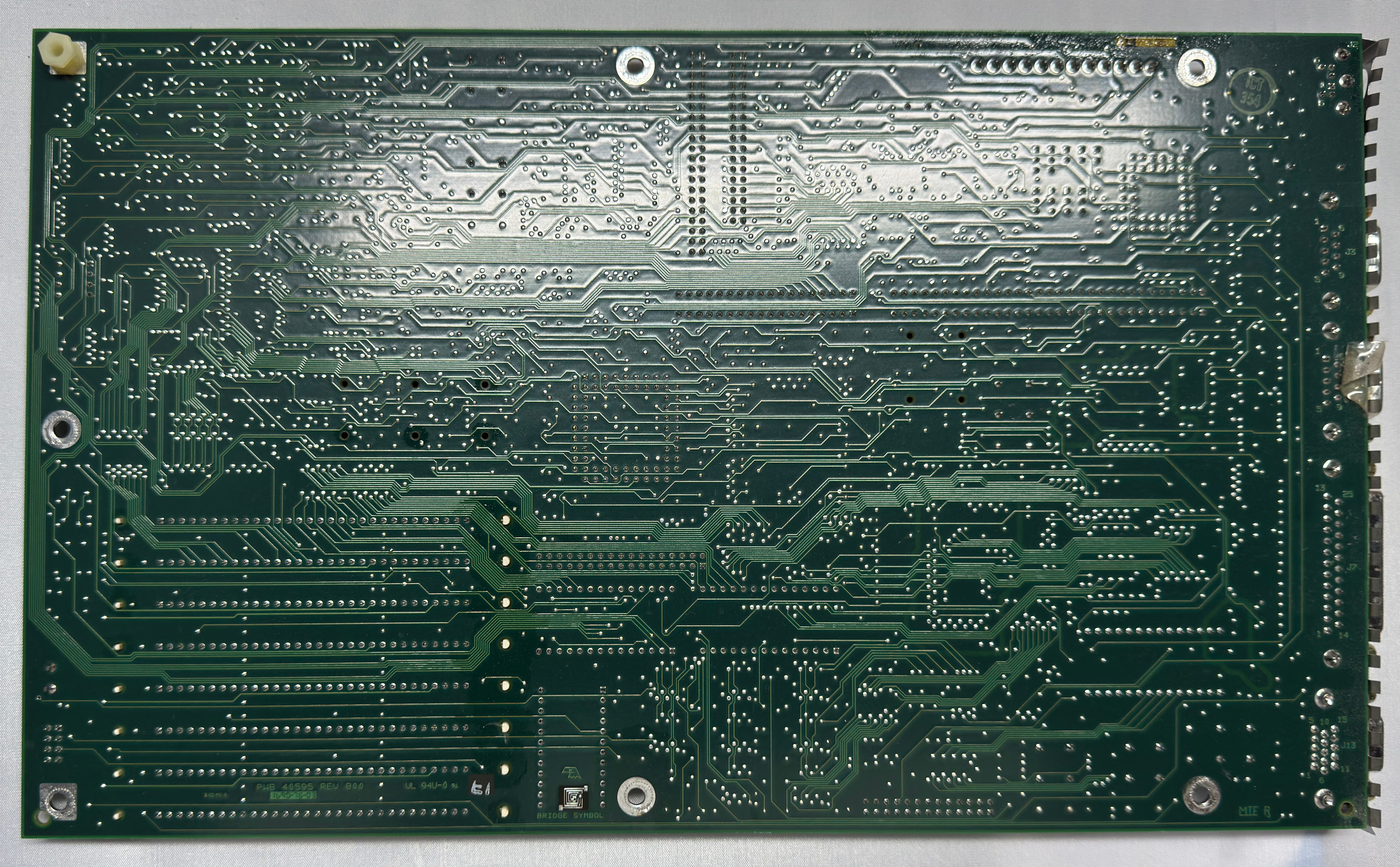
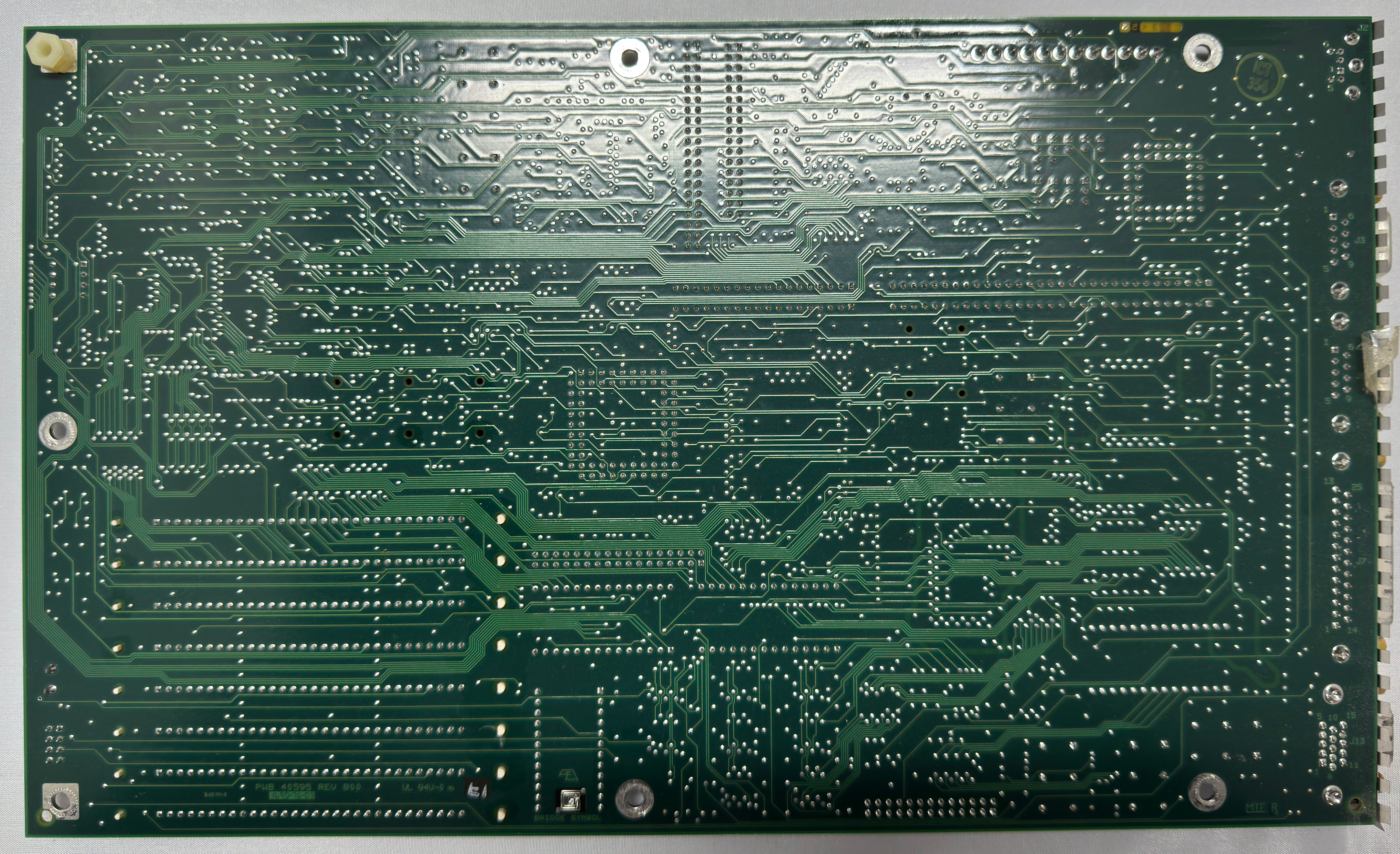
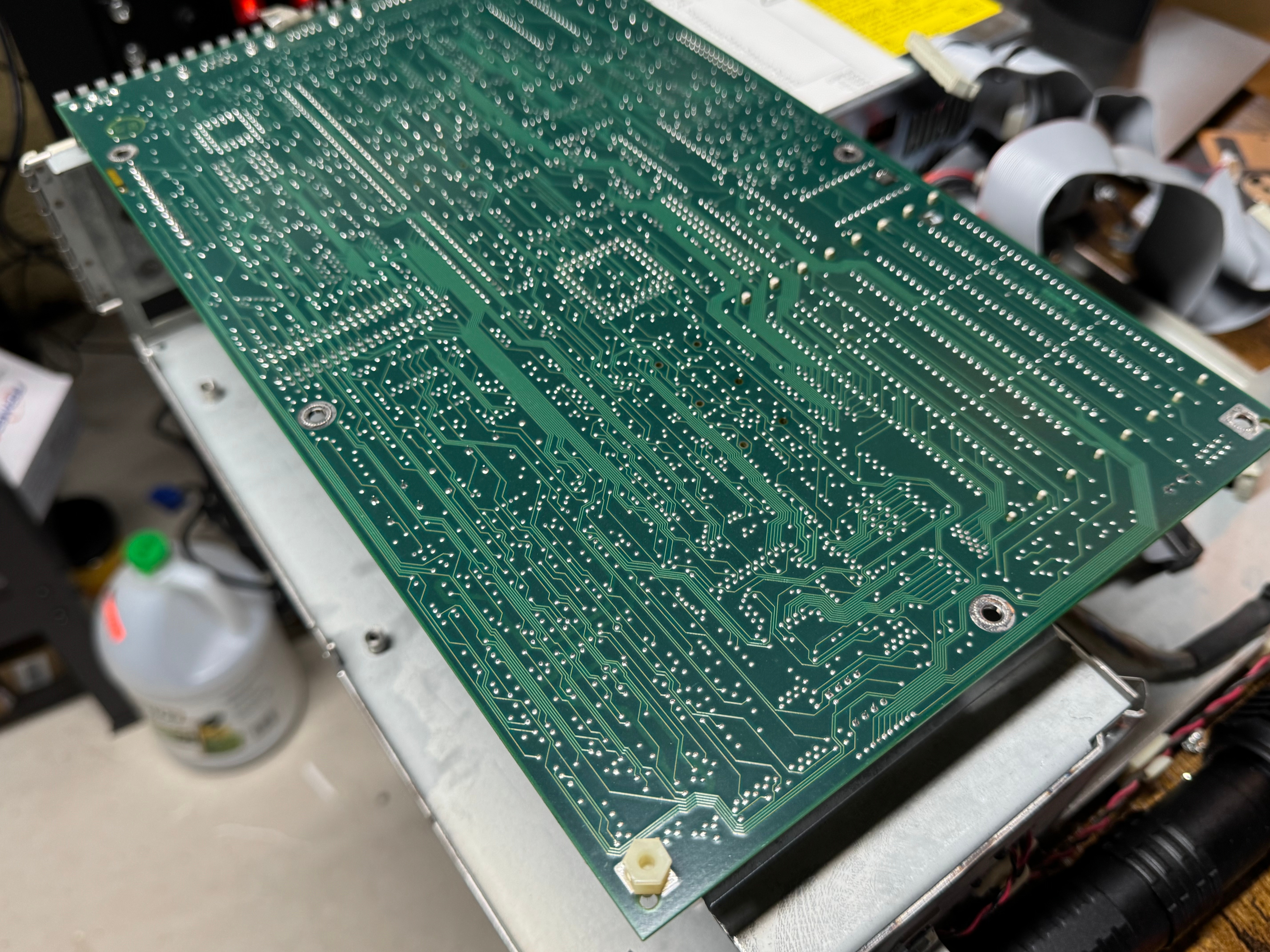
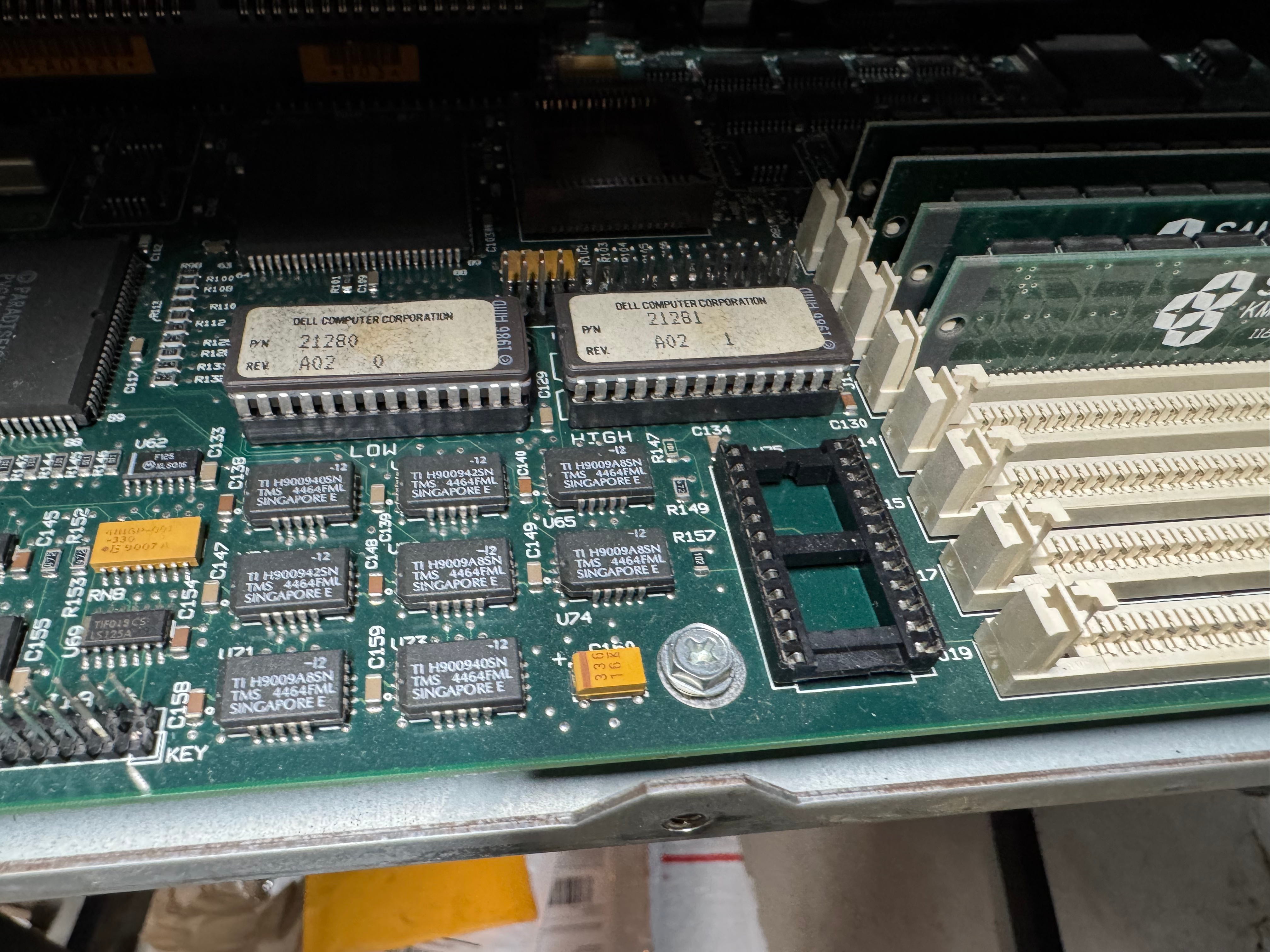
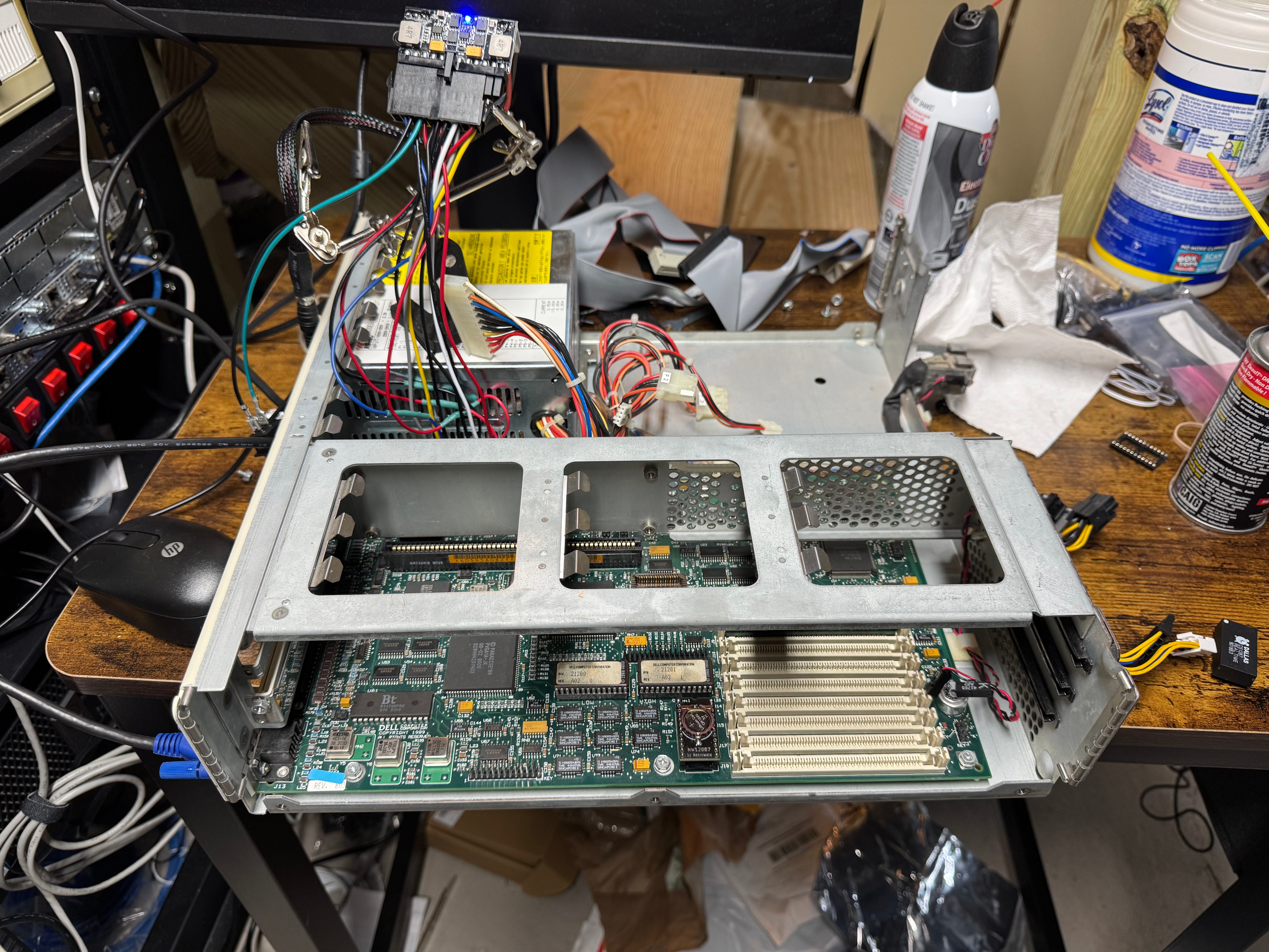
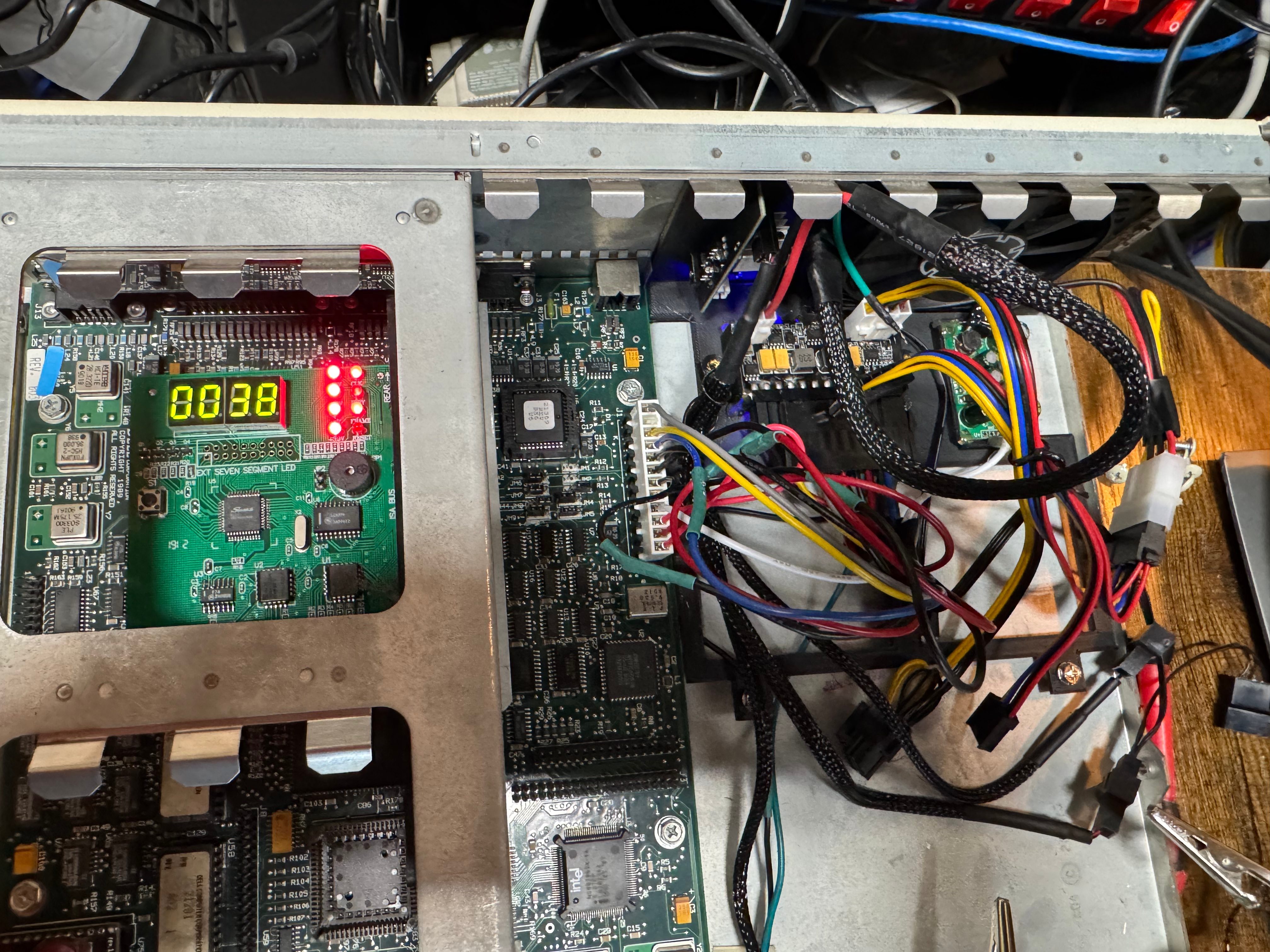
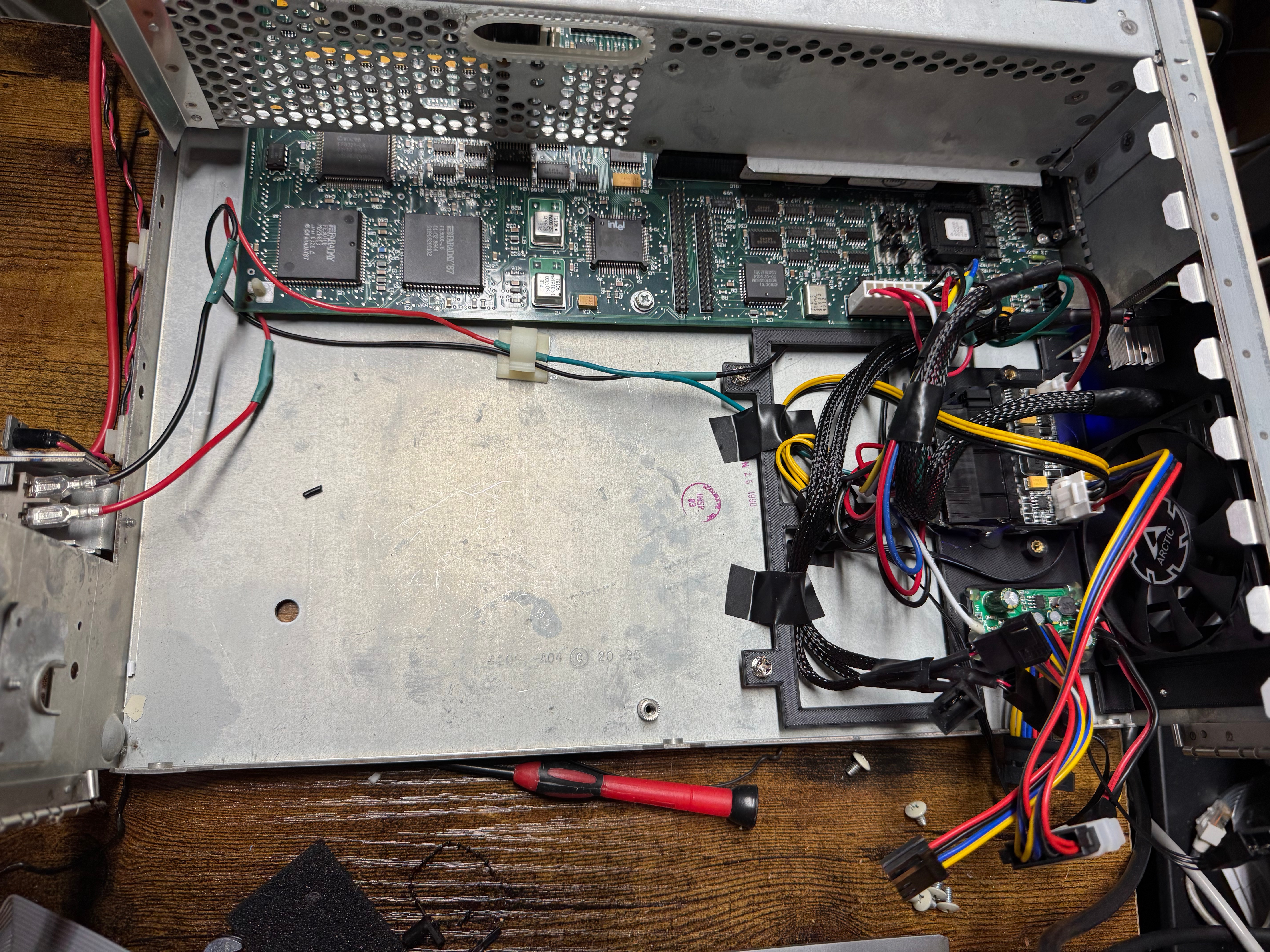
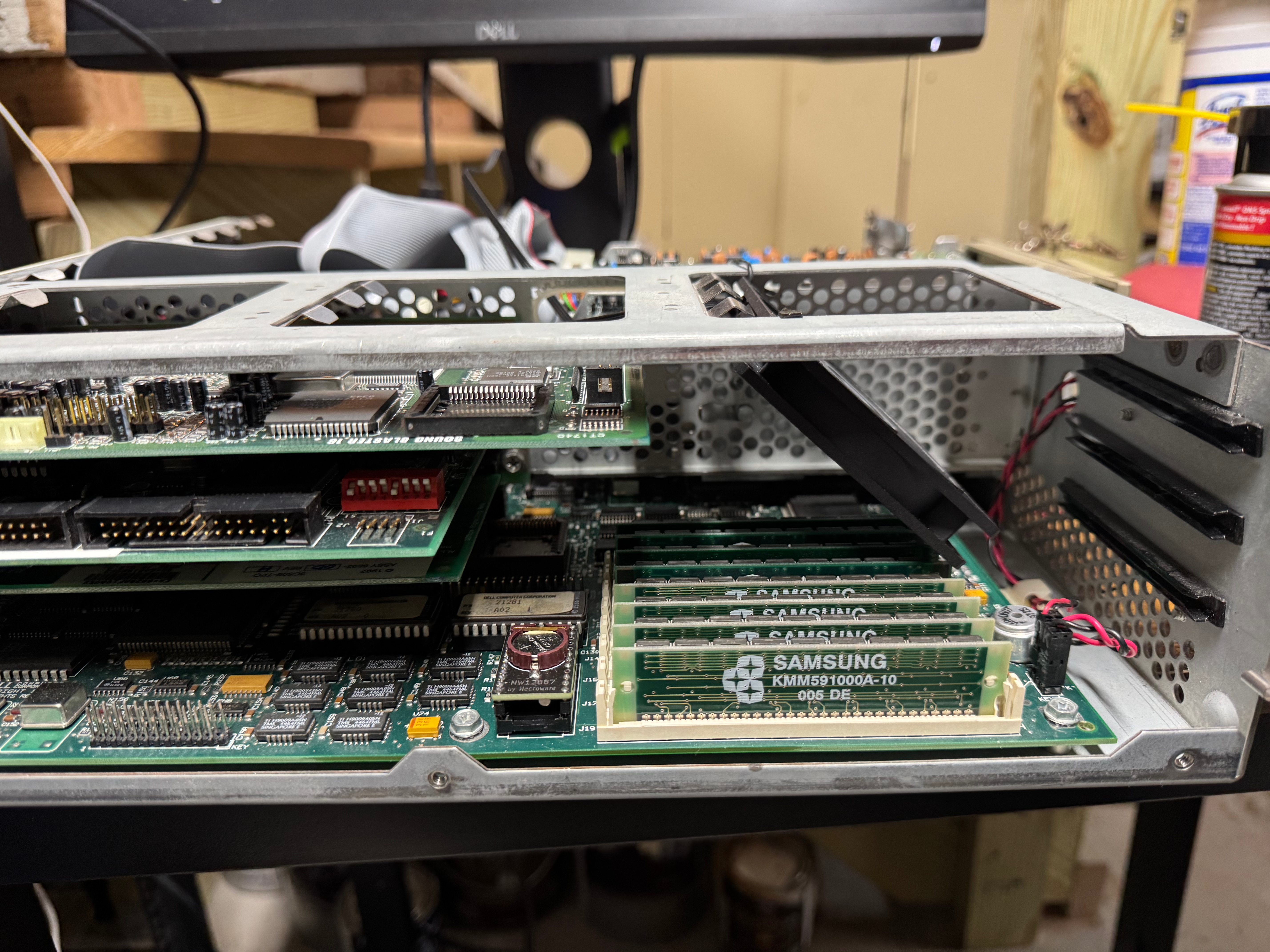
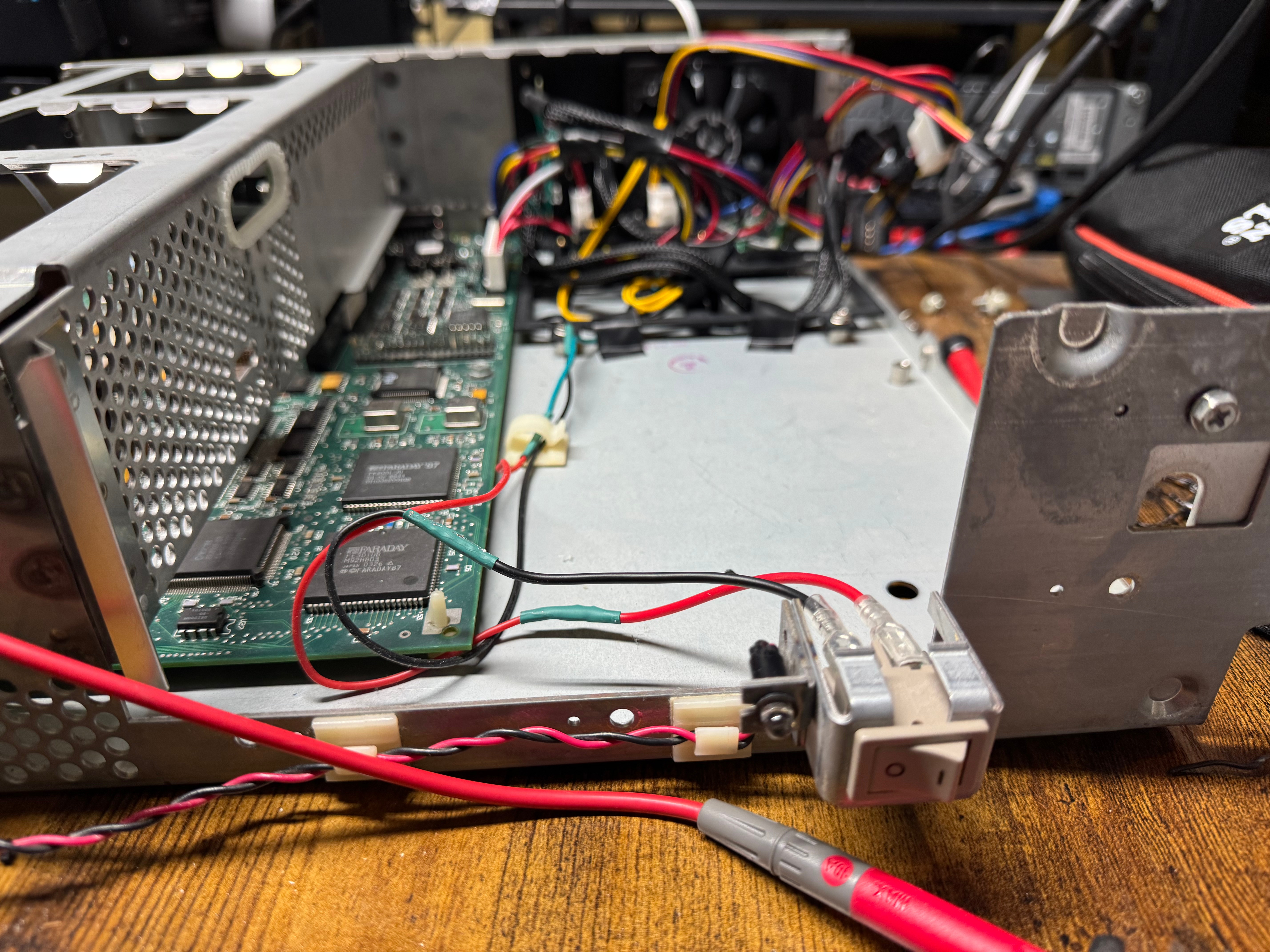
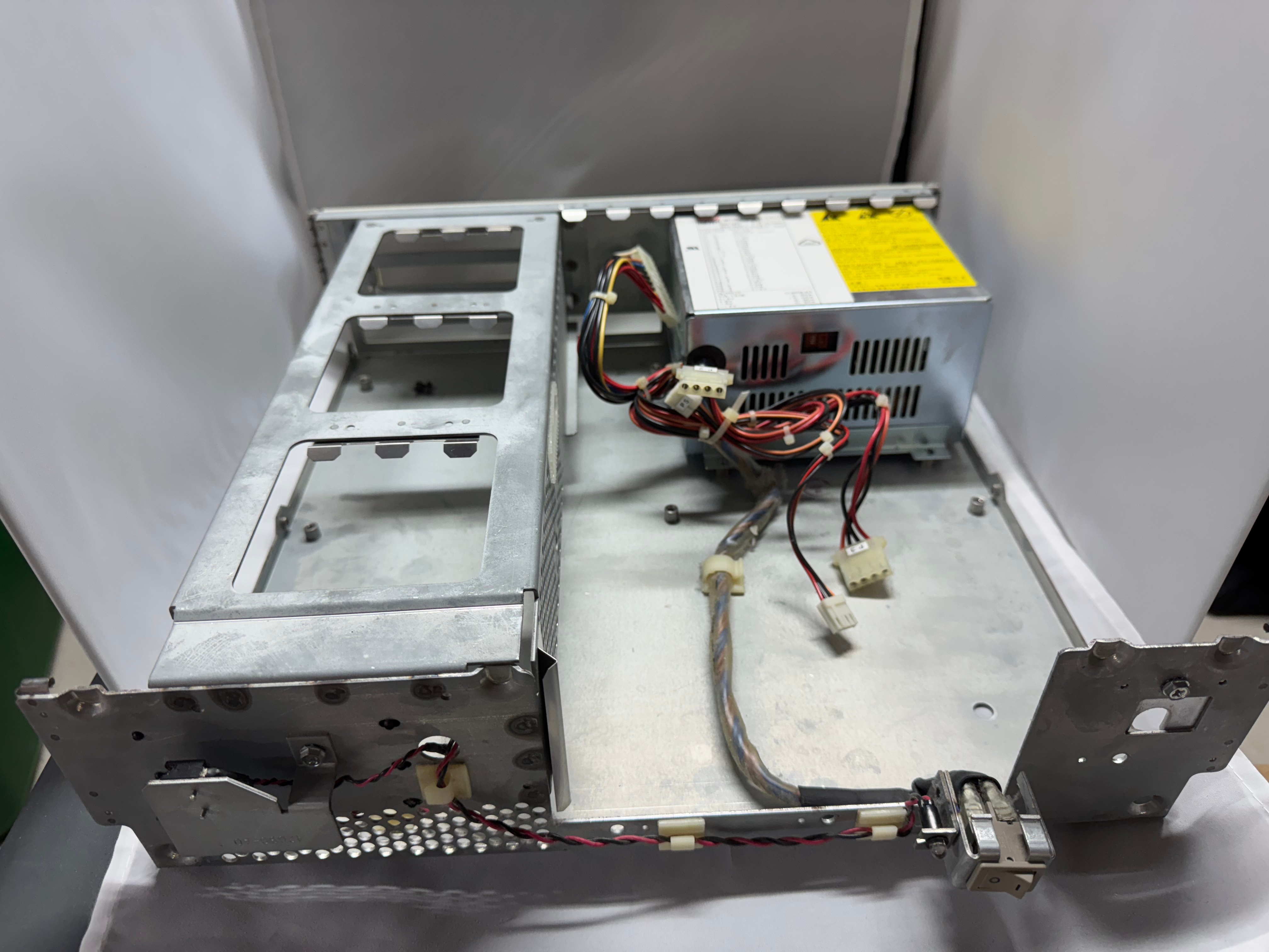
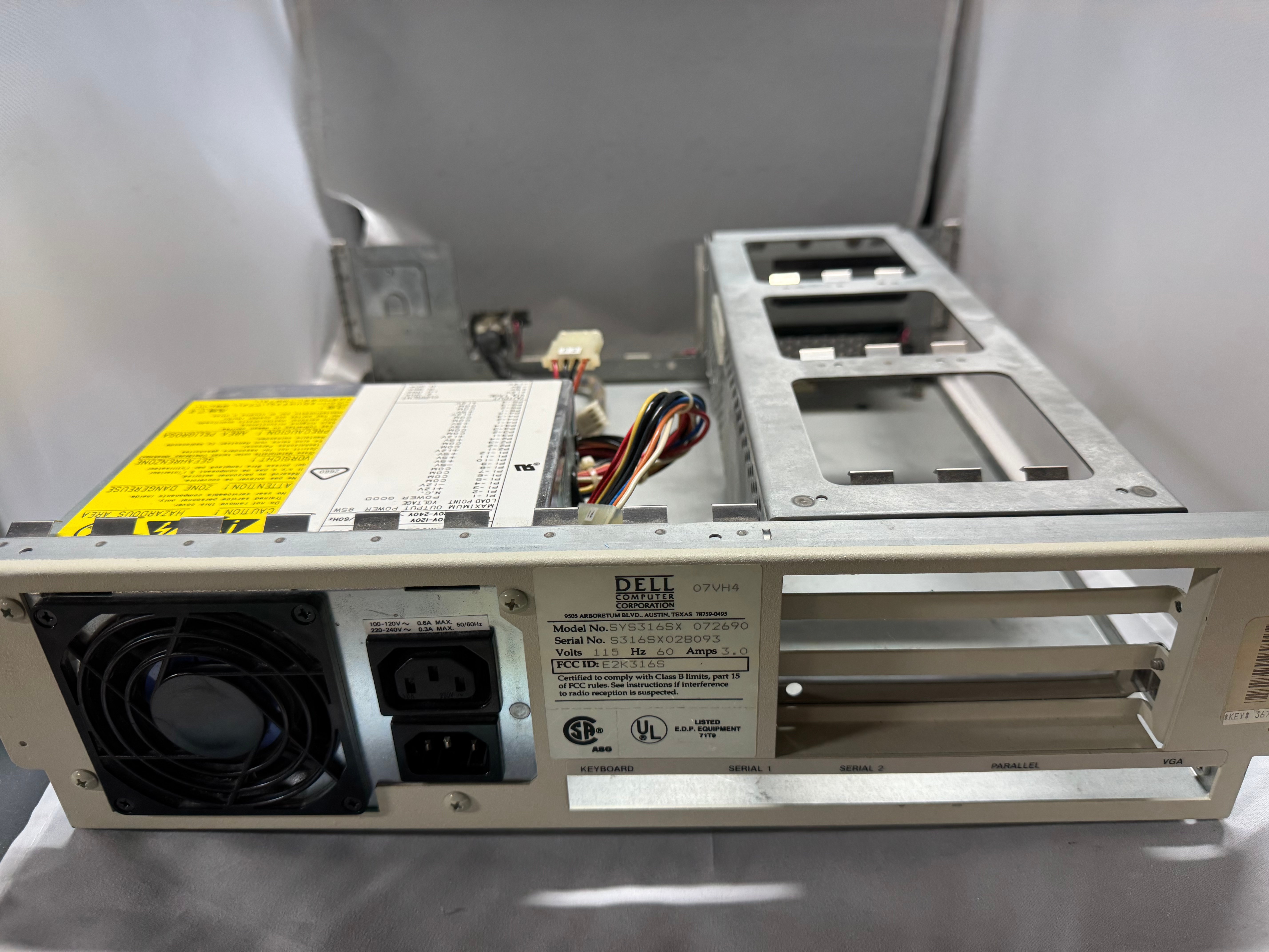
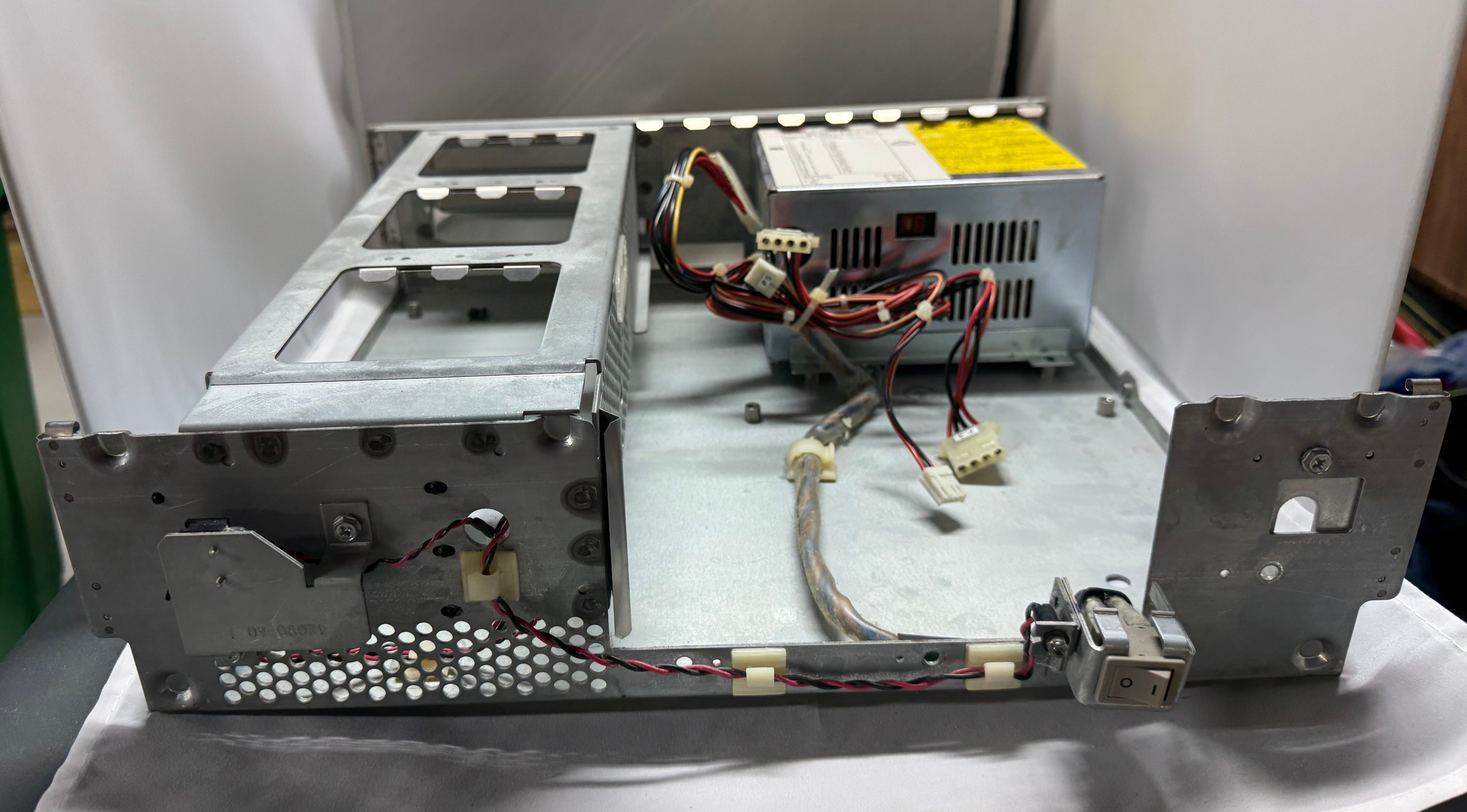
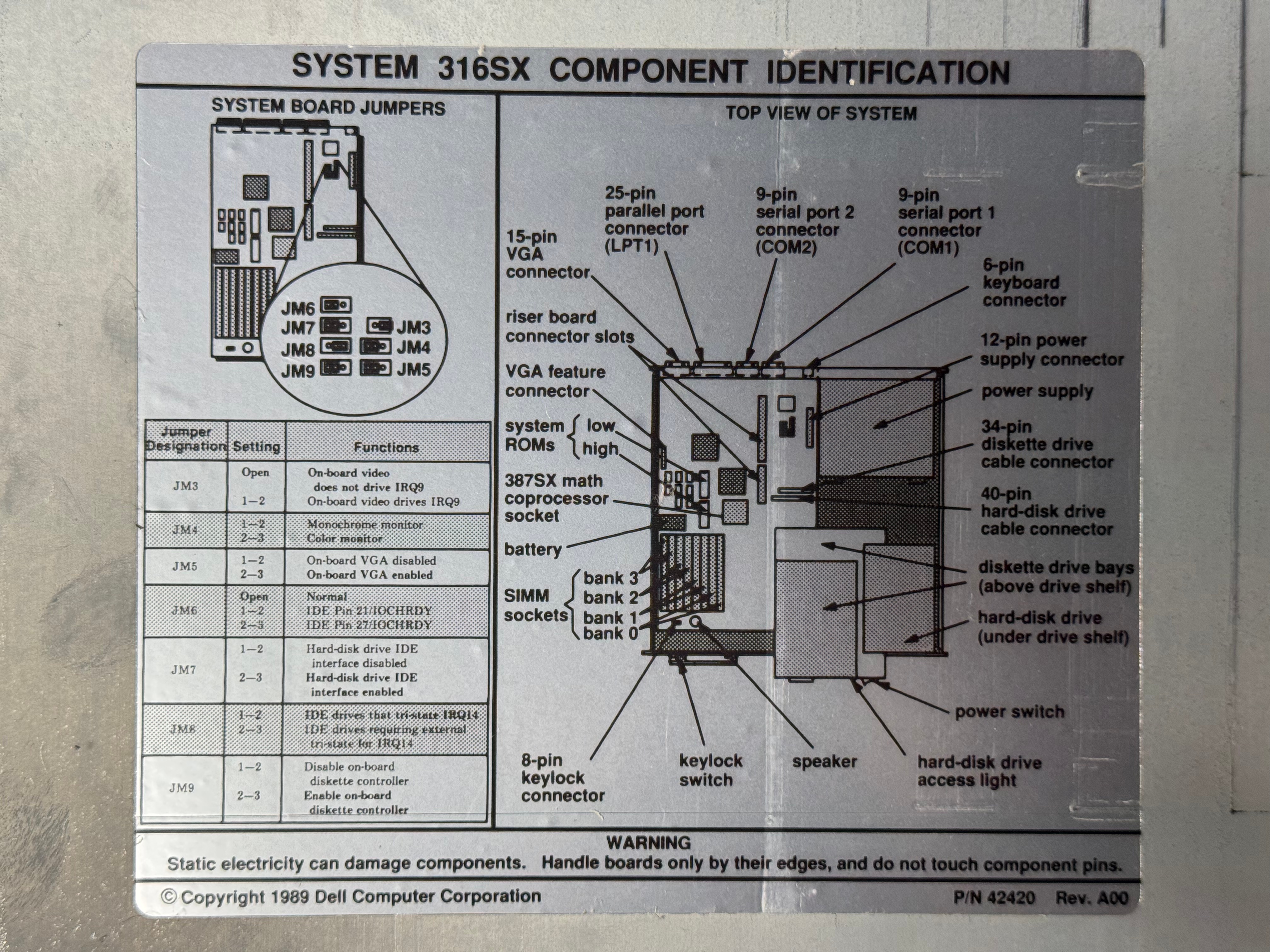
I took the case off for the first time in 30 years or so, and it all looks in good condition. No rust or corrosion from anything leaking. Below are some nice photos of the board and the system. It is a Dell 316SX (no math co-processor) Motherboard revision B03. (I had some glare on the board, so I uploaded several photos)
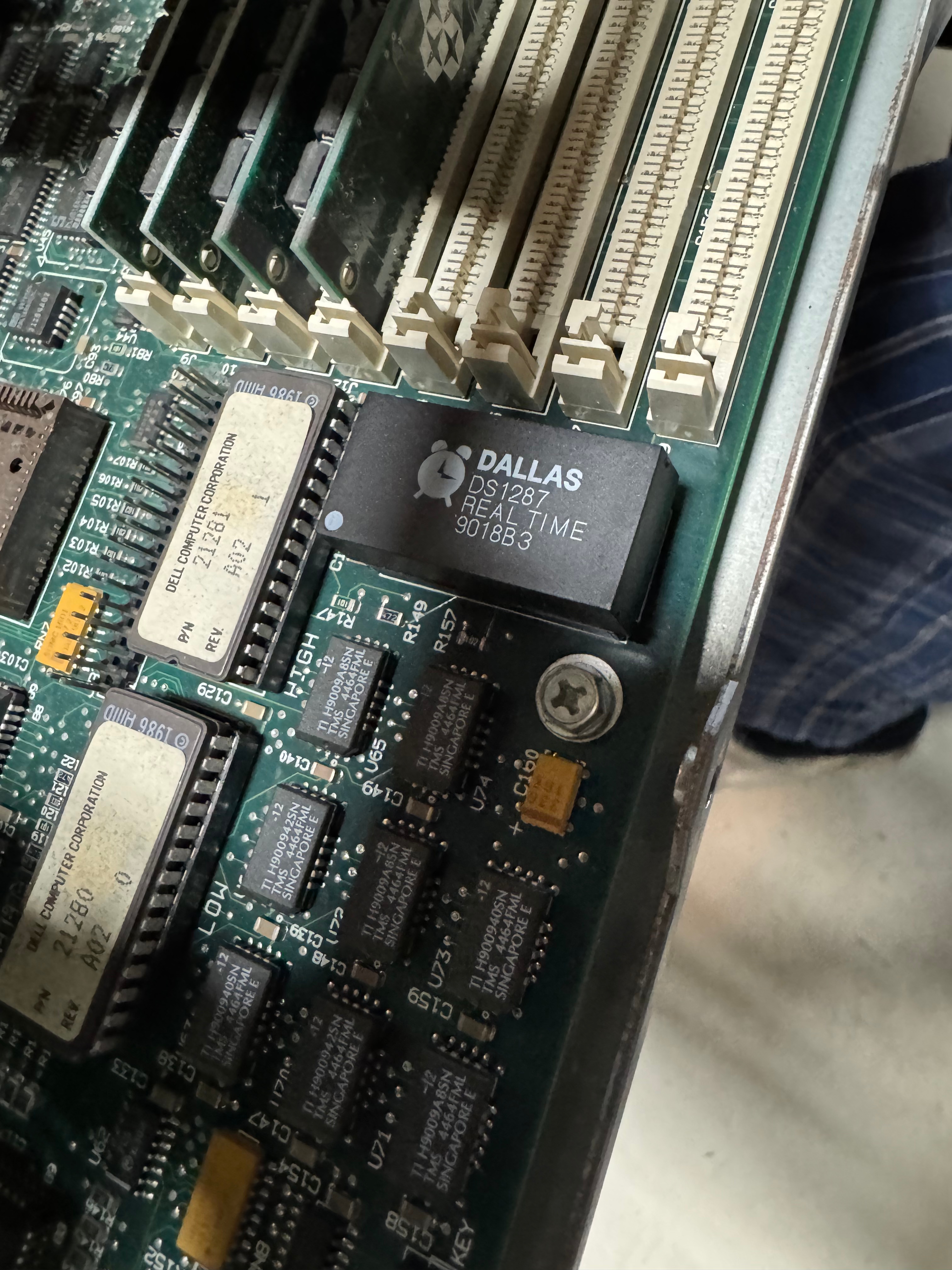
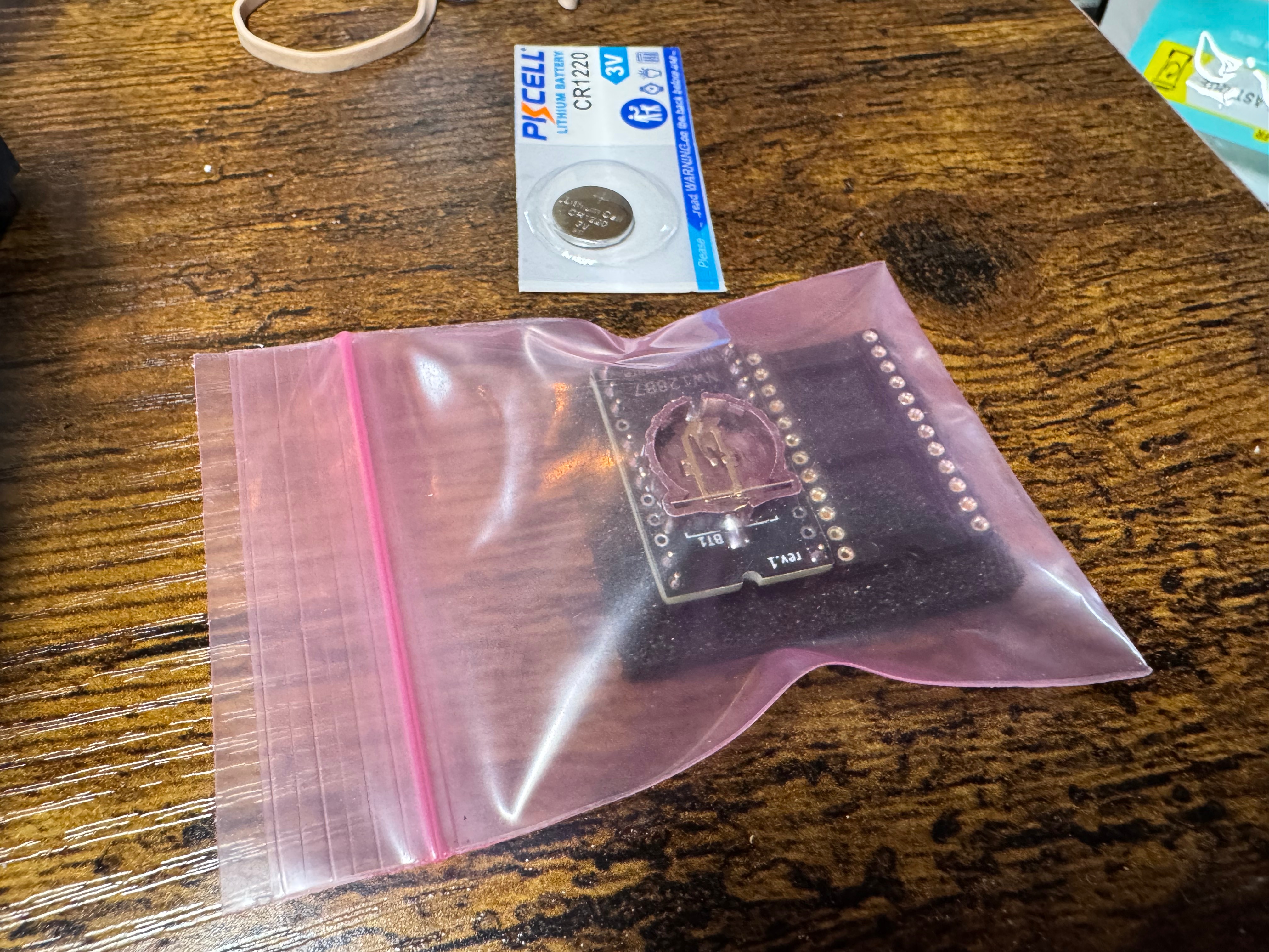
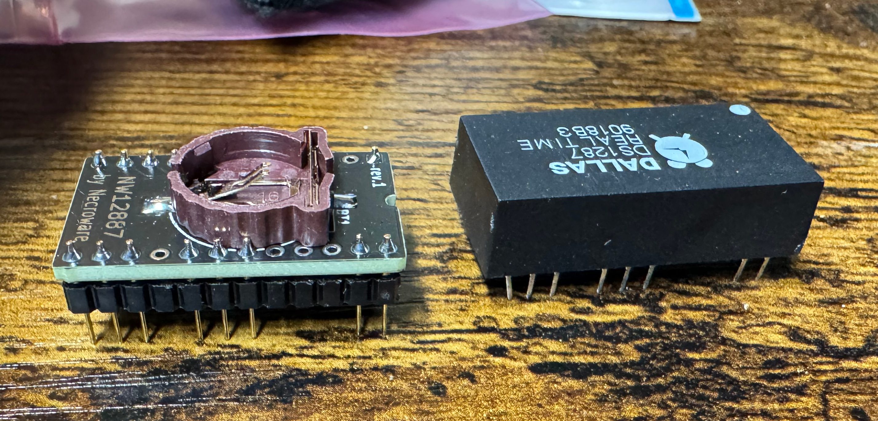
My first thought after chatting with ChatGPT was that this system was old, and had a Dallas clock chip. The Dallas DS1287 is a real-time clock with built-in battery — a common failure point in old PCs because the internal battery can’t be replaced easily. The internet said some 386 systems will fail to post if this chip is completely dead. I order a replacement (https://www.ebay.com/itm/134217827379) from the same vendor I got the PS2 Serial adapter from. Wait a few days, it comes, pop it in AND… nothing…
Old Dallas ChipClock ReplacementClock Replacement and Dallas chip side by sideBIOS Revision and slot for Dallas Chip
At this point I figure we are probably looking at a power problem. This system is 35 or so years old, its big capacitors failing would not be a shock.
Power Supply Restoration
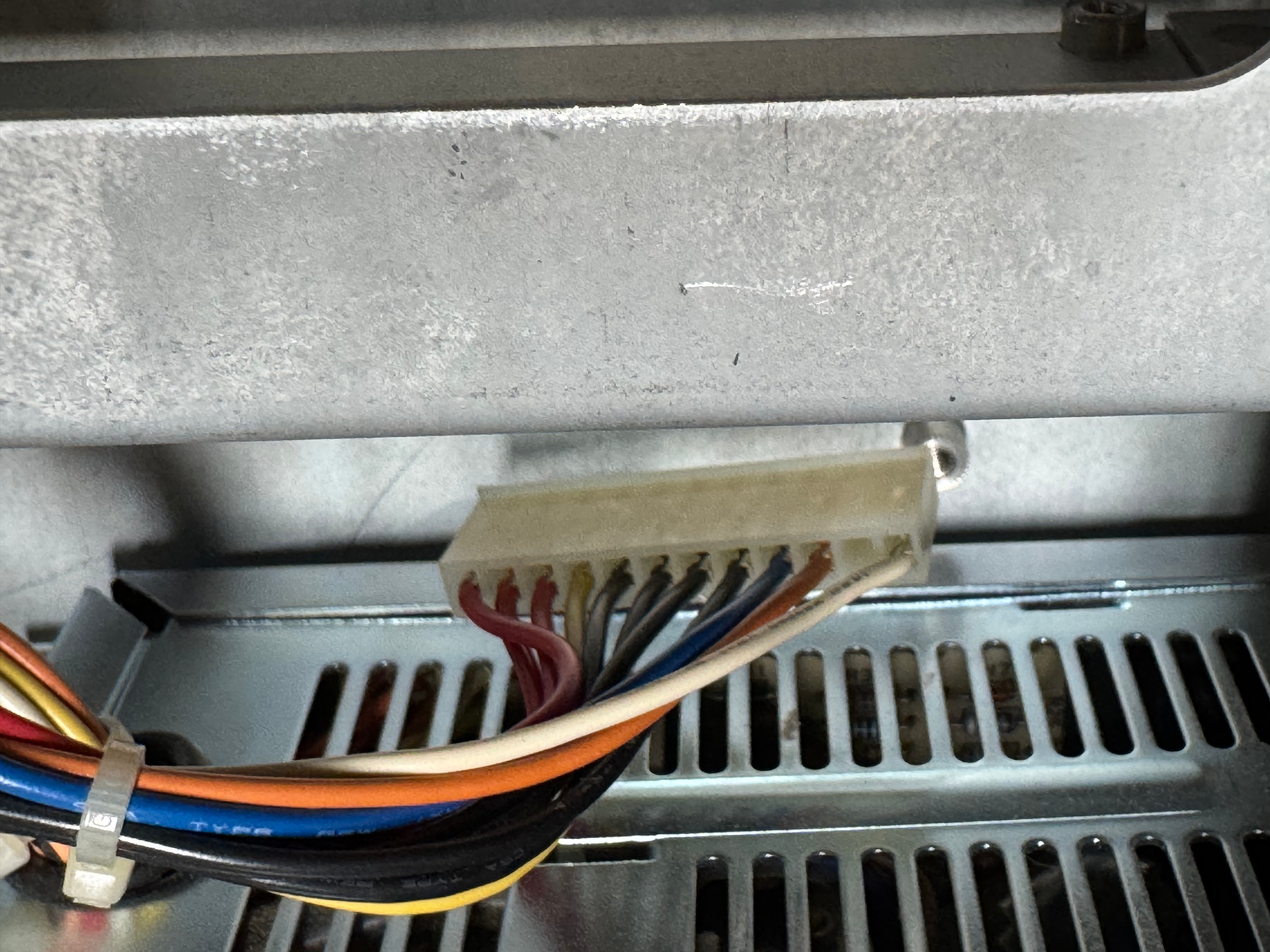
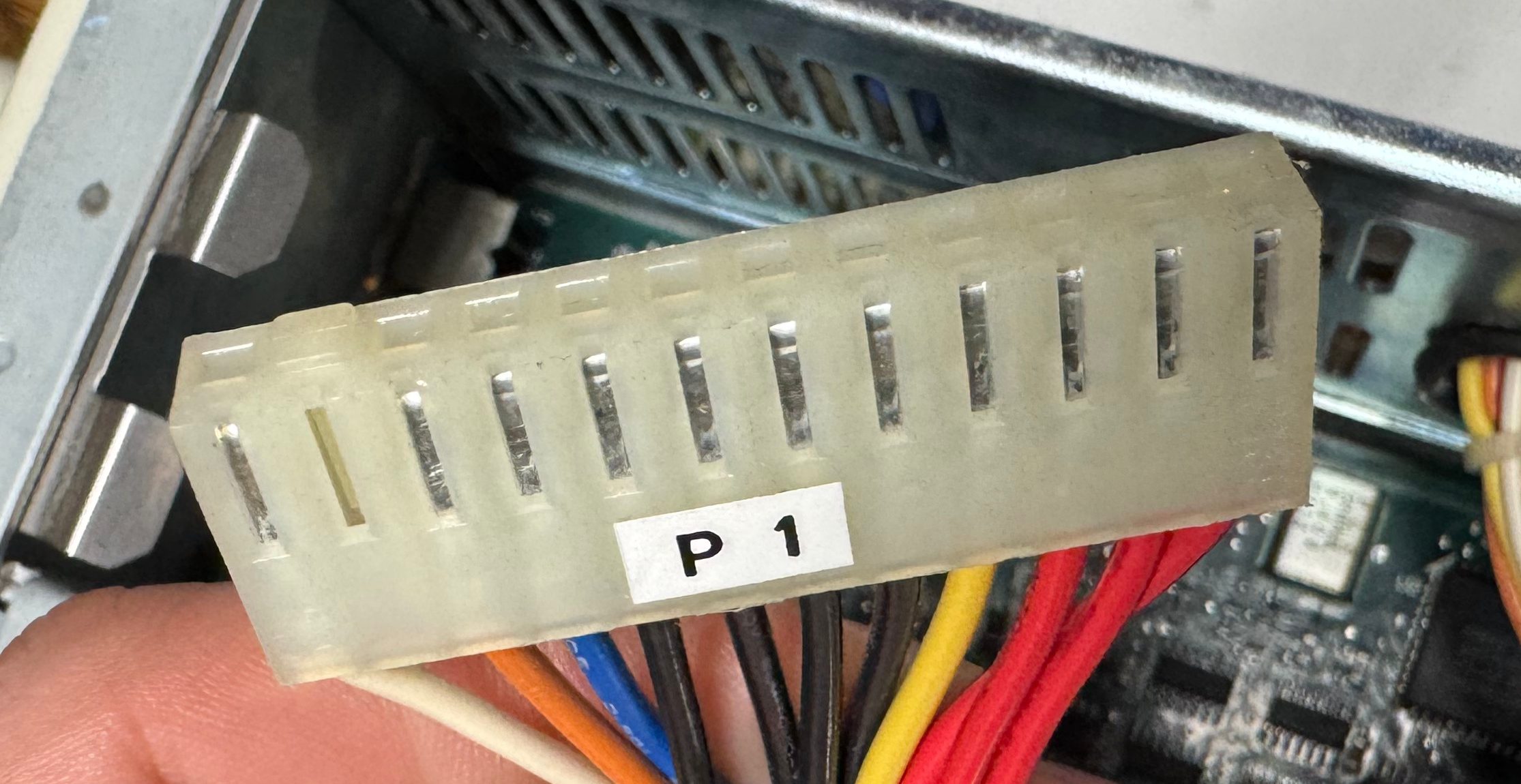
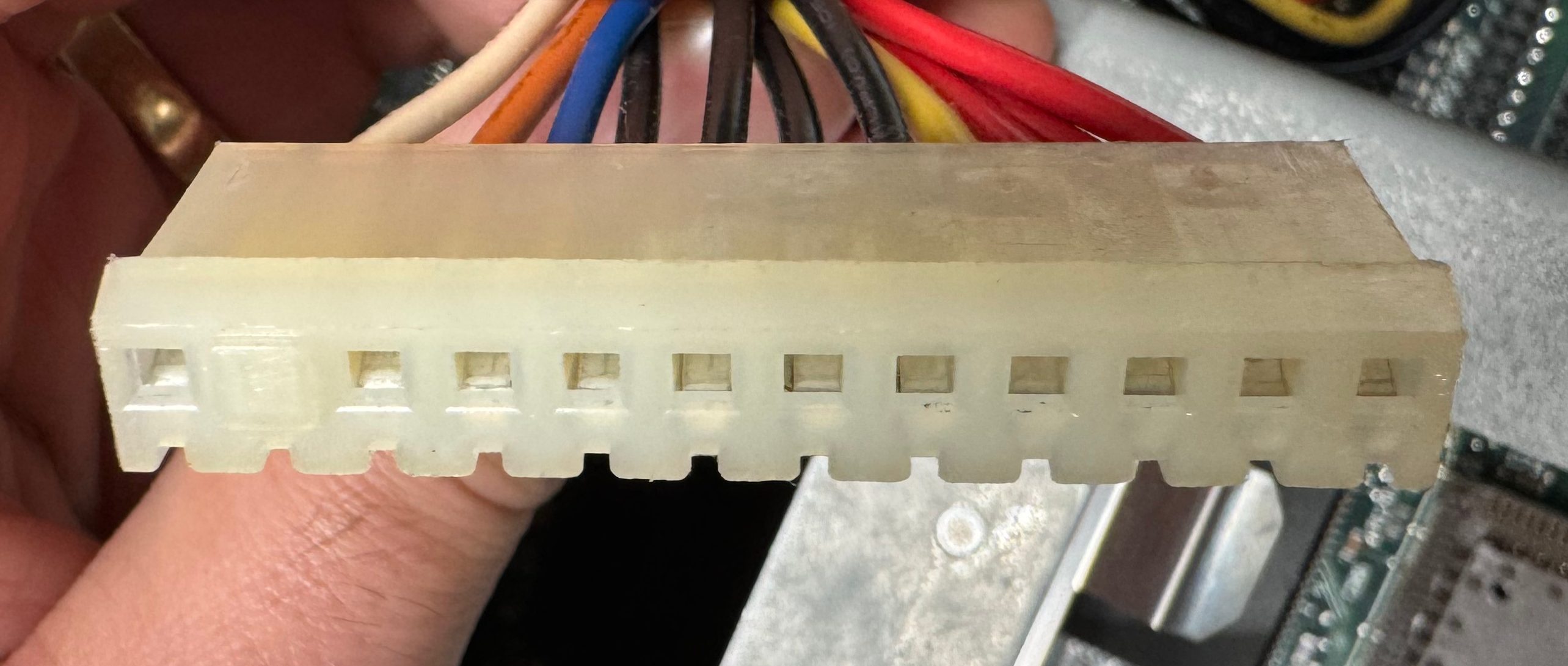
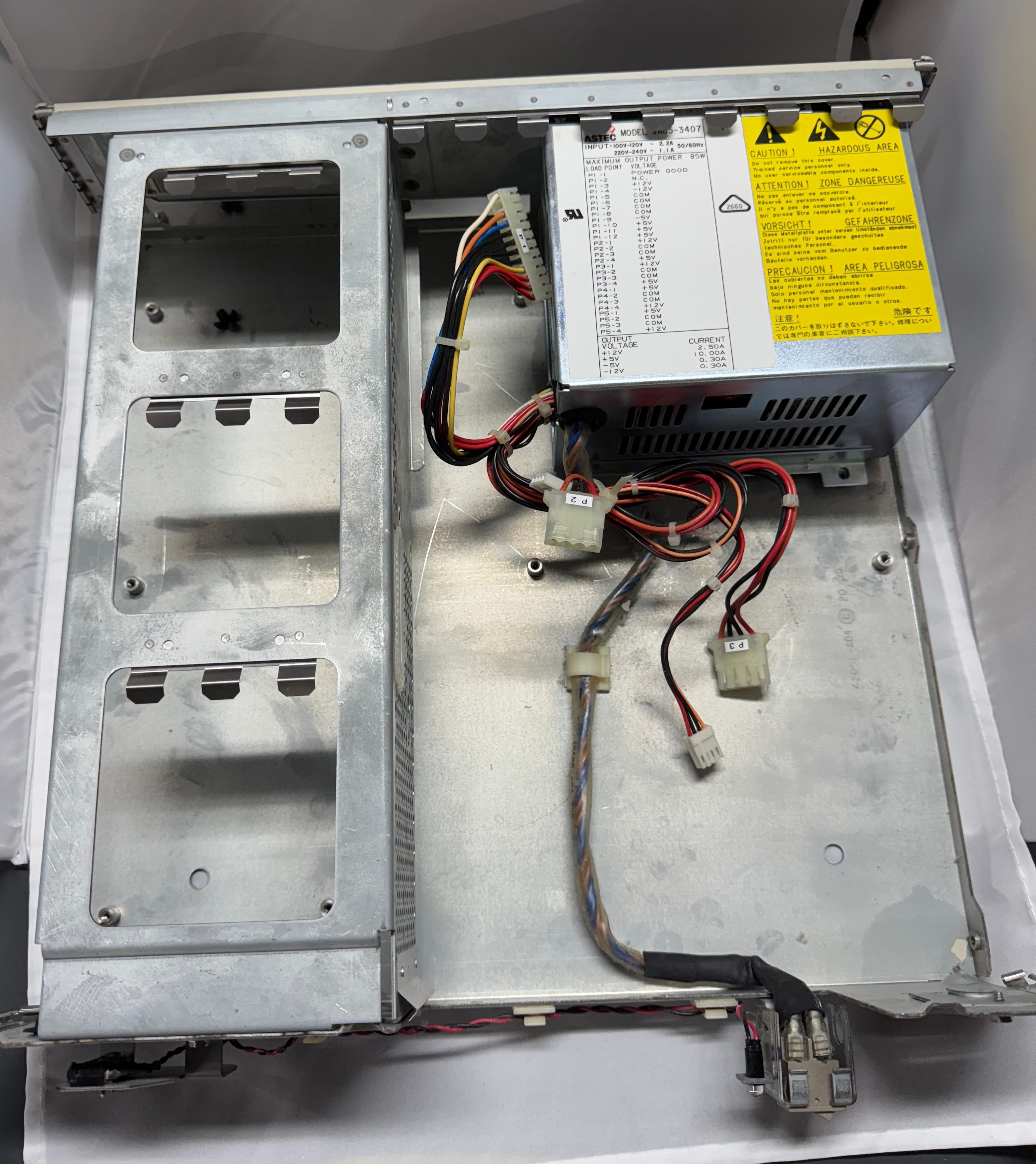
I don’t love dealing with power, but here we are. I got the multimeter out and started probing the connections I could see. This is an older power supply than anyone today is used to, this is following the original IBM AT standard, minus the fact that is a seemingly proprietary Dell header on the motherboard. For anyone with the same system, the connector is a MOLEX 09-50-8121, more on that later.
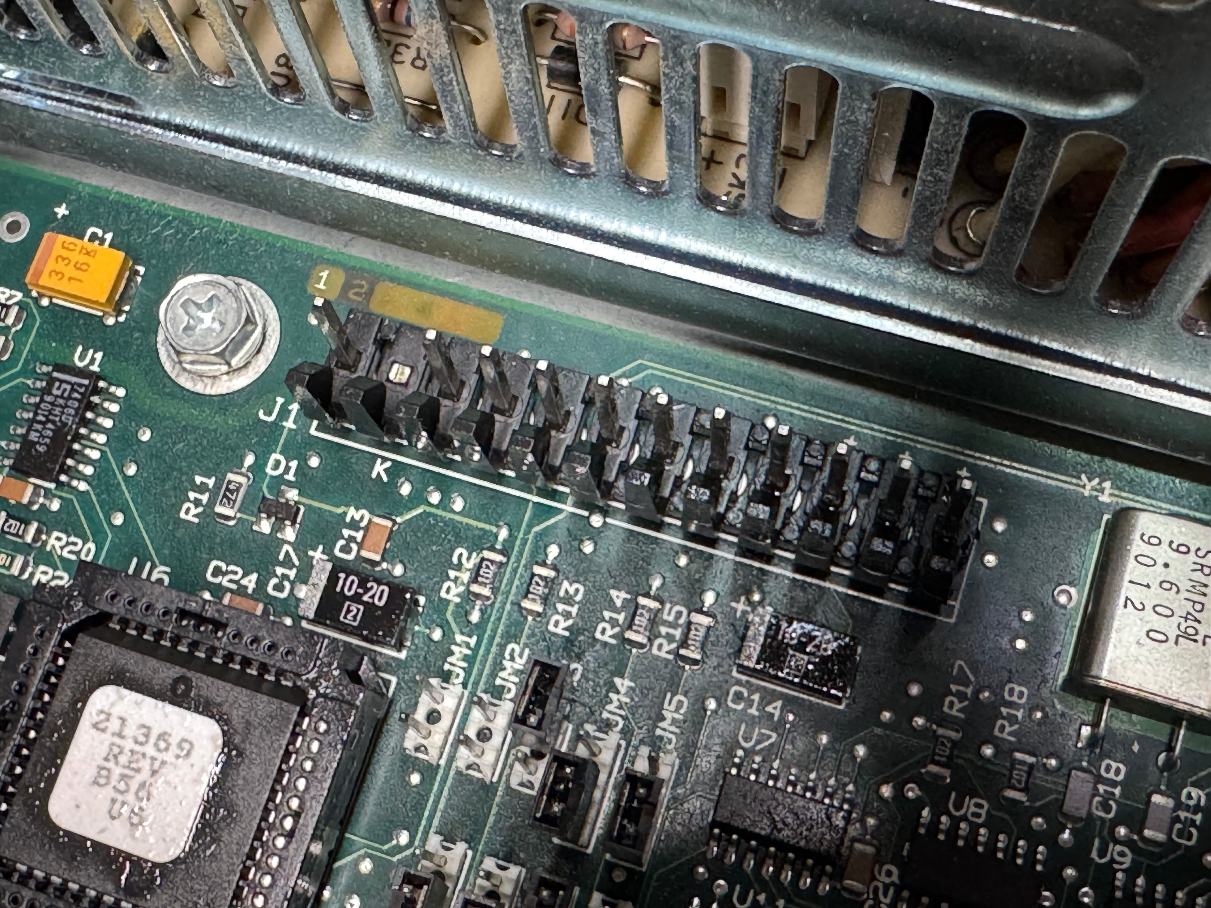
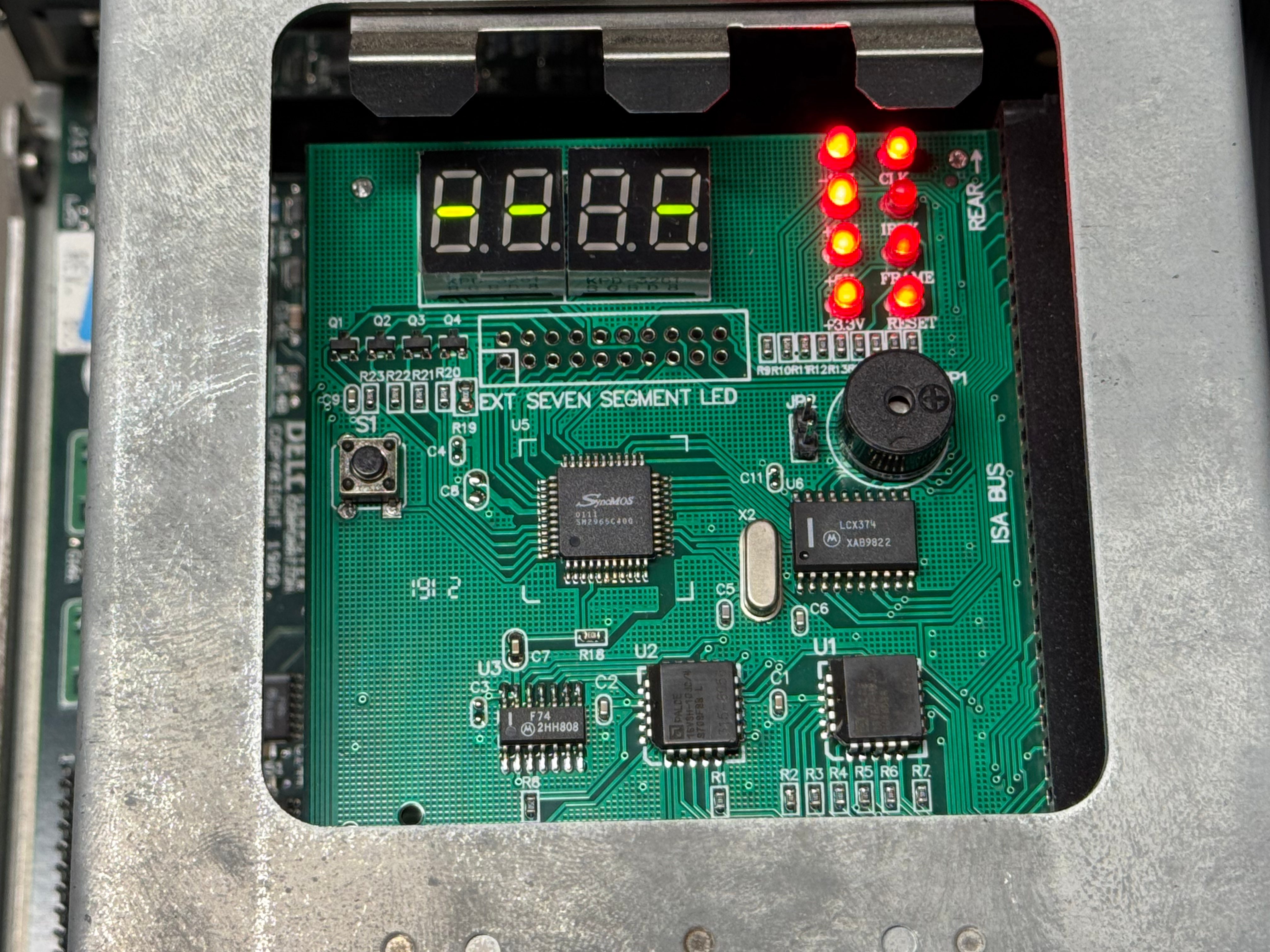
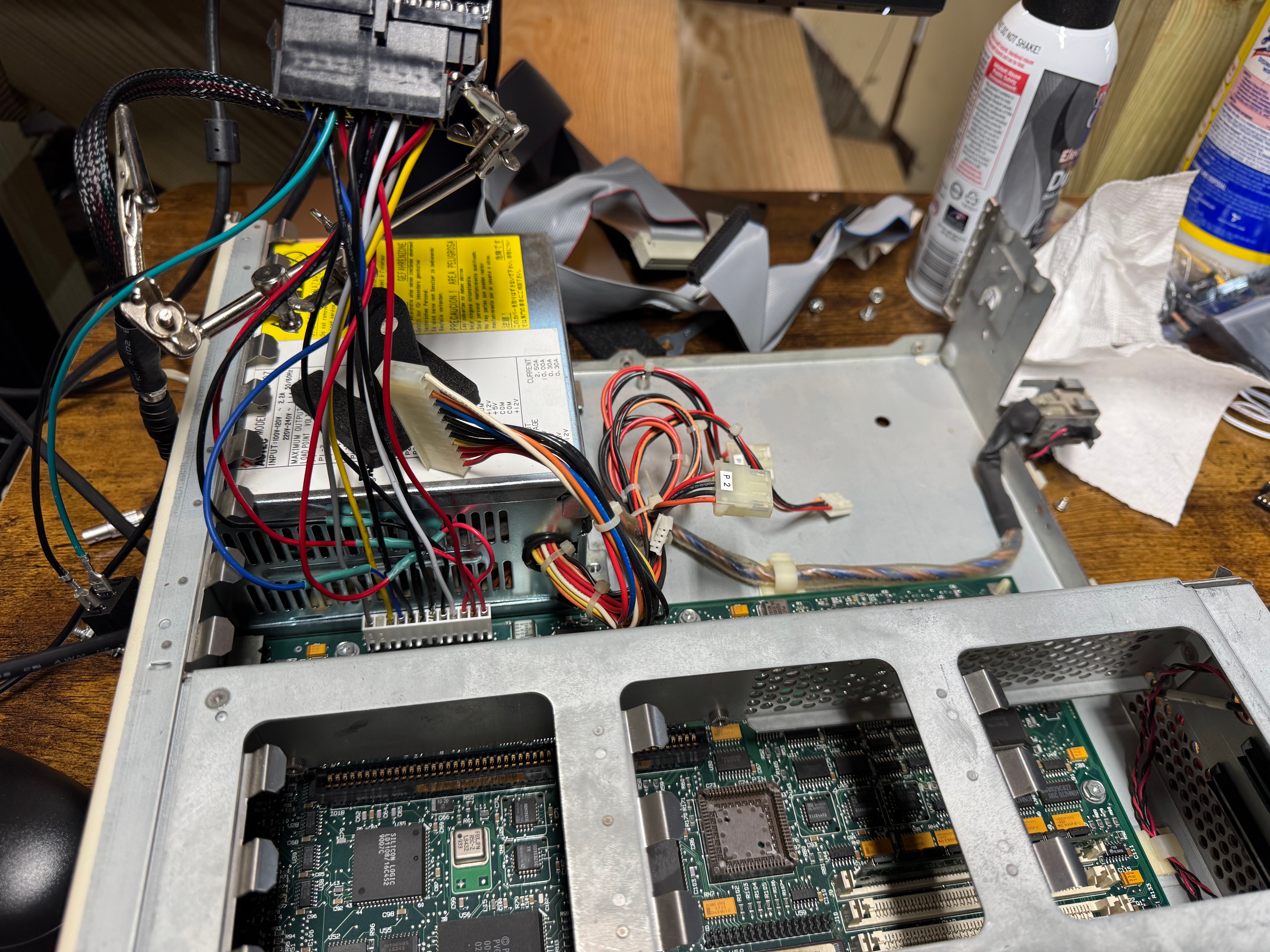
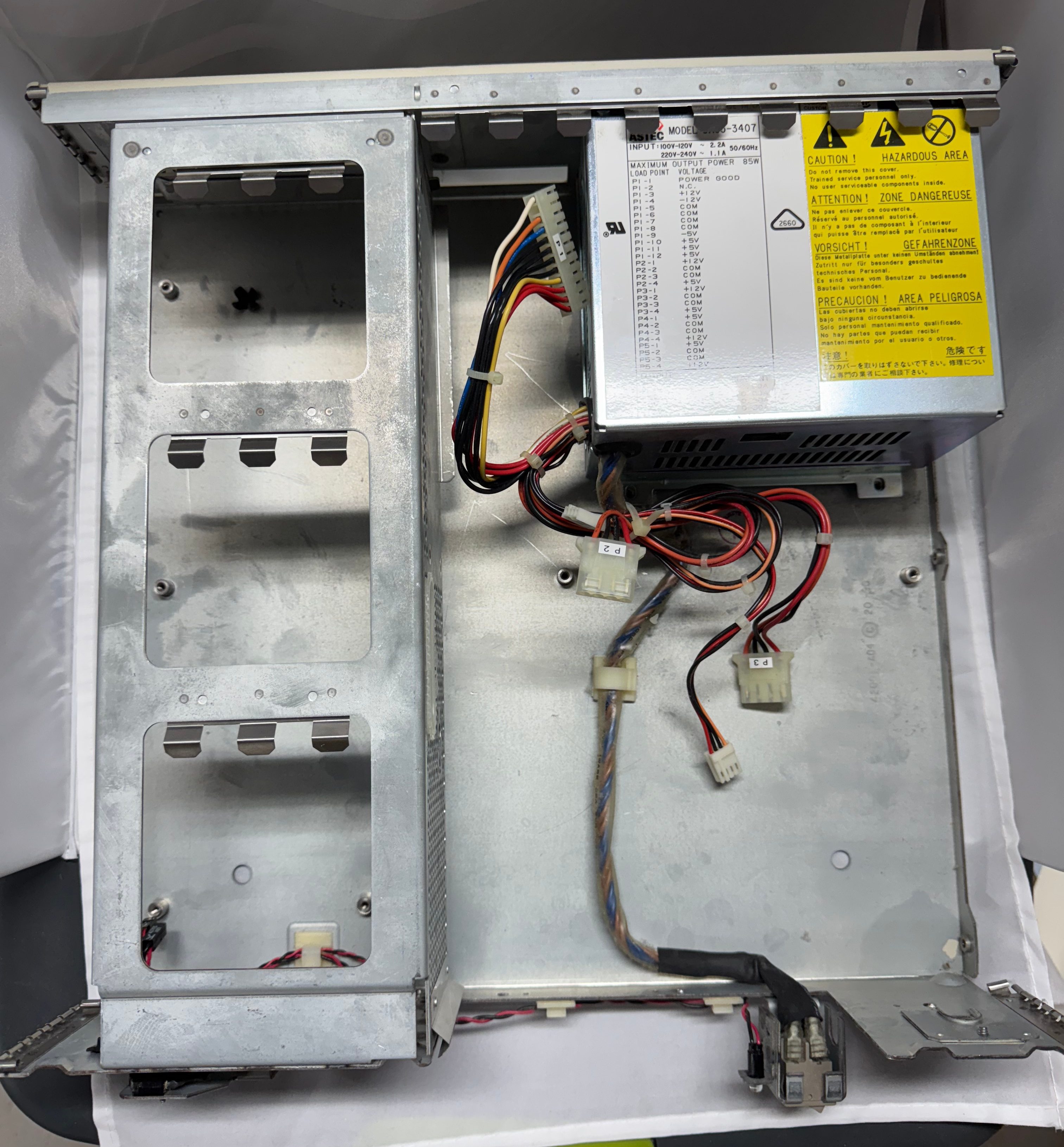
Reading the motherboard pins +12V, +5V looked good, -5V, and -12V looked a tiny bit low, but within tolerance for a system like this. I popped in a ISA/PCI diagnostic card and see that the RESET line is holding high, and the CPU is never being released. Then I probed the last line on the motherboard PSU connector, POWER GOOD; this pin goes high once the power supply has all the lines at a good voltage, releasing the processor to start… processing… That line never came up for me, and thus never released the processor. I opened the power supply and saw it was 2 boards with many wires going in-between them. I may eventually repair this power supply, but I do not feel like tackling that whole thing right now. I put that power supply on the shelf, and started the task at building a new one to meet this computers needs.
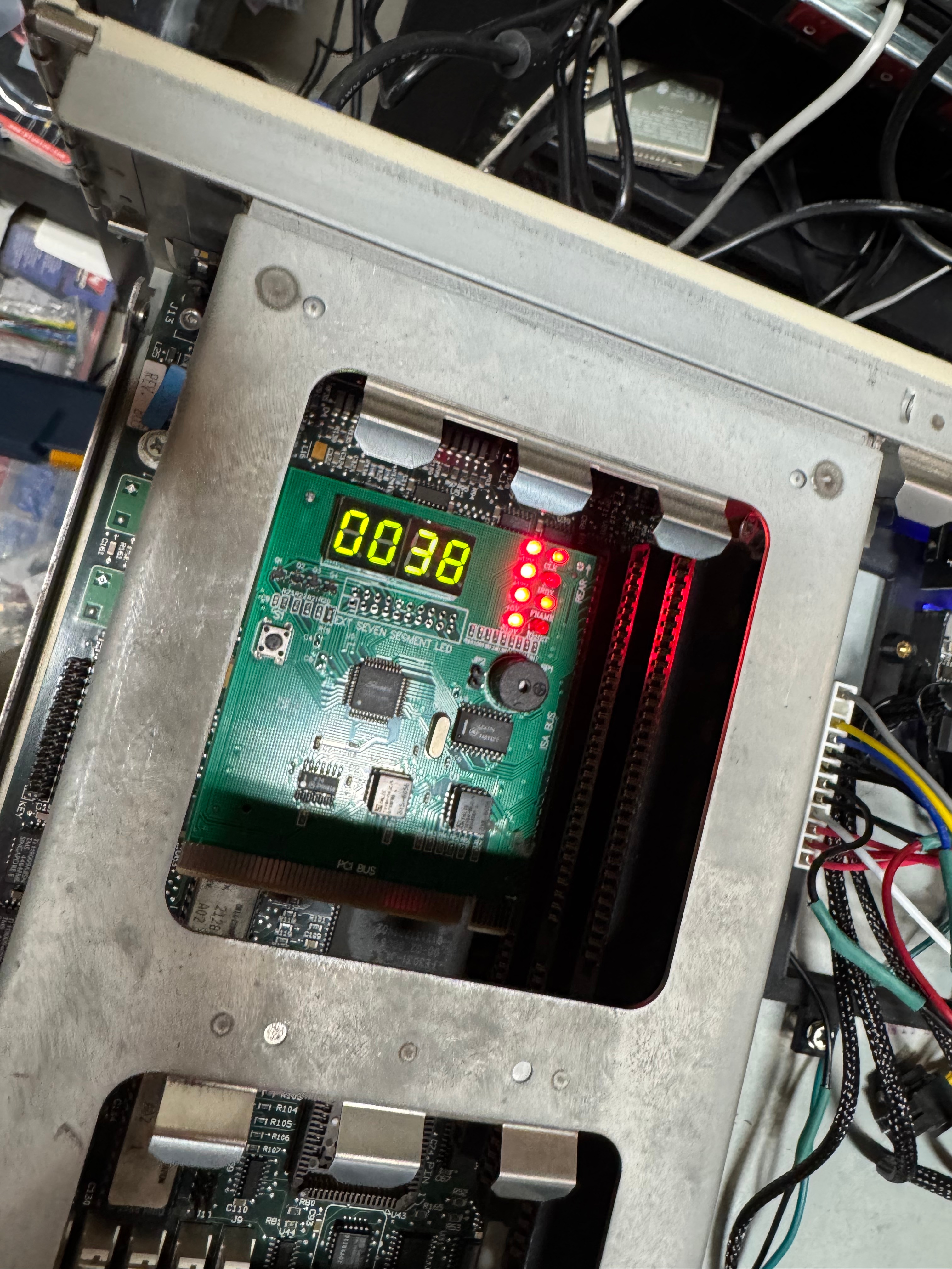
Bad POSTGood POST
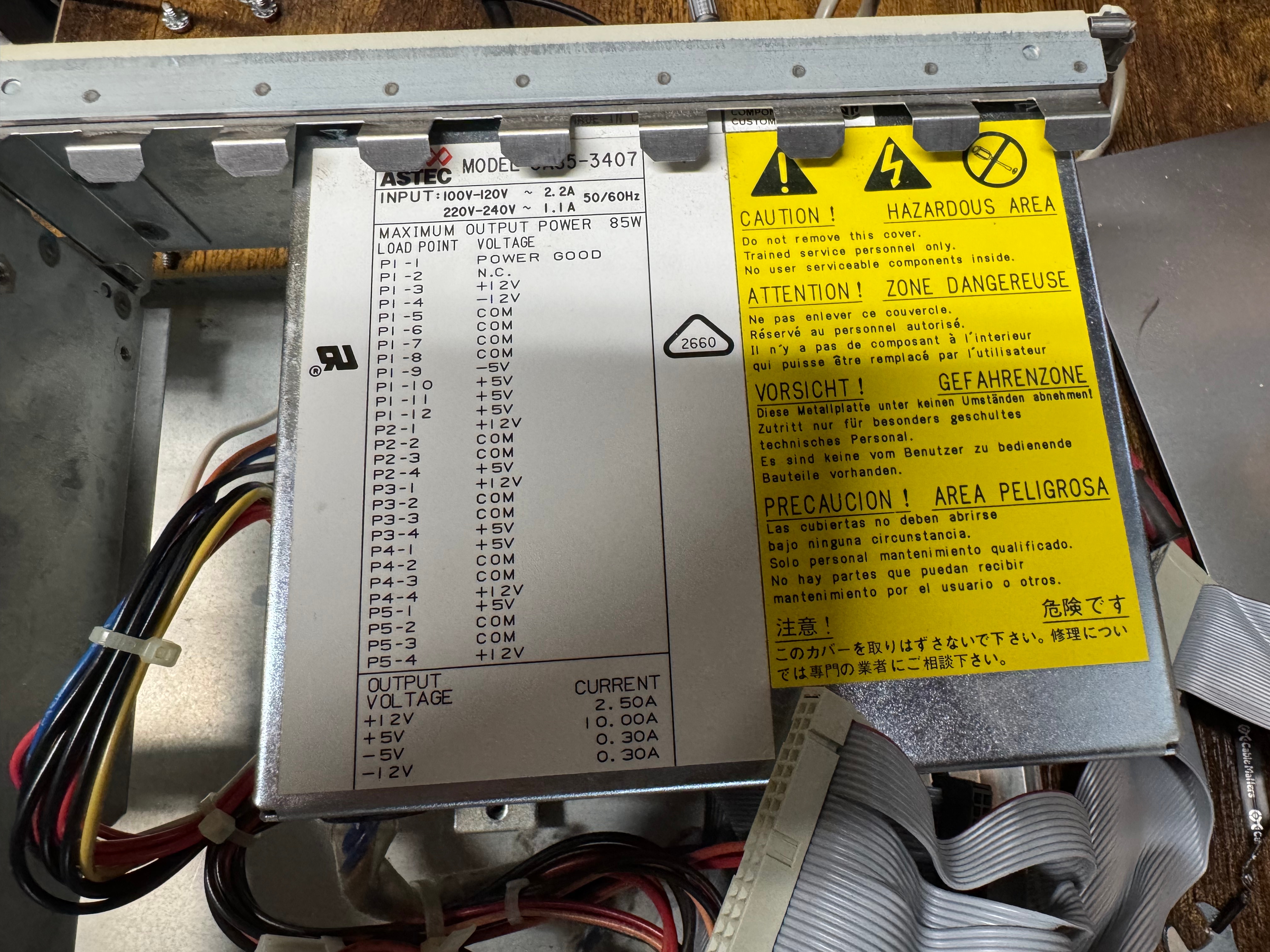
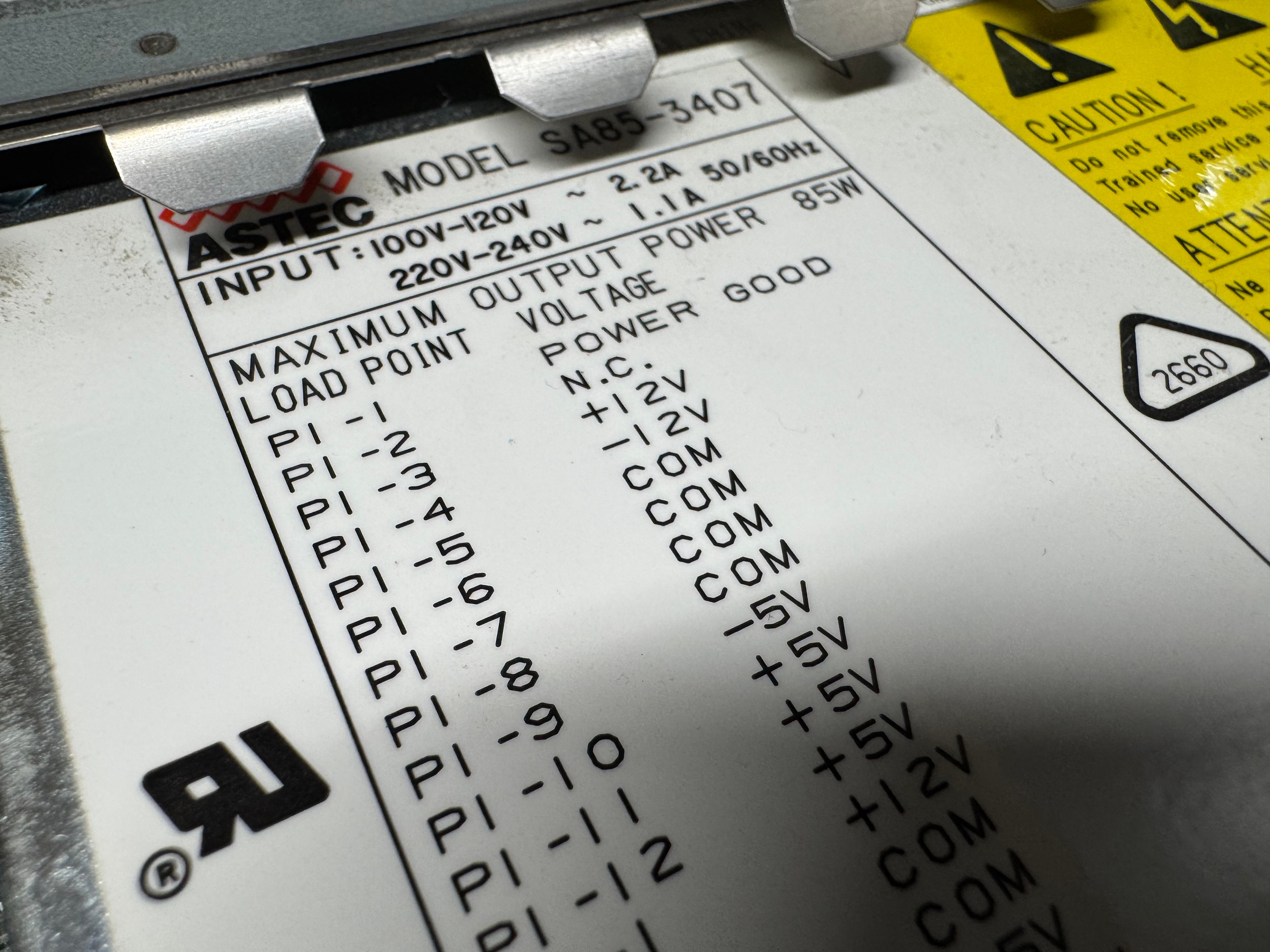
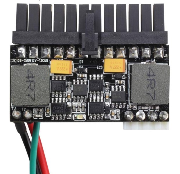
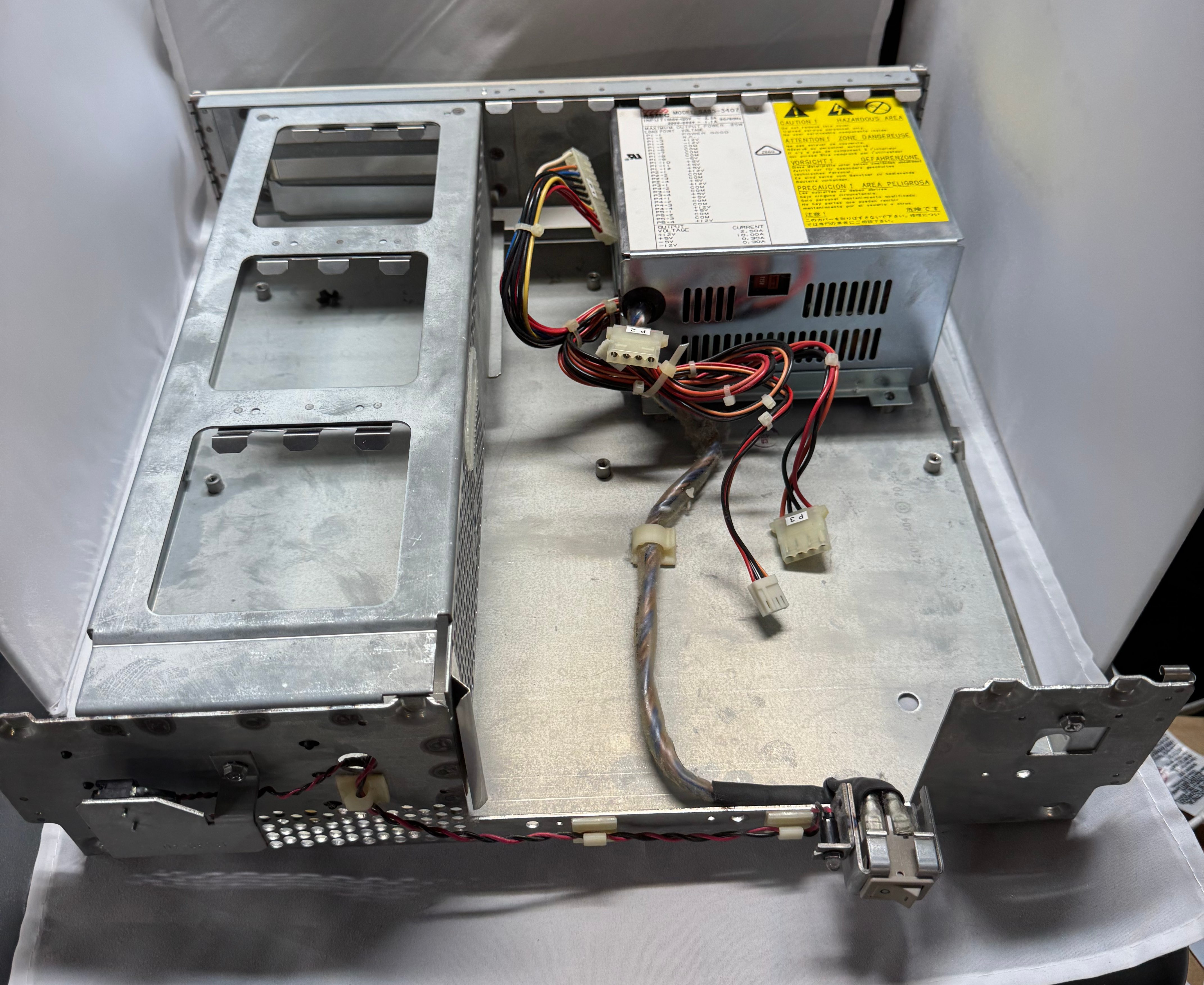
A while ago I bookmarked this device, https://www.tindie.com/products/dekunukem/picopsu-adaptor-for-ibm-5155-ibm-pc-compatibles/, an ISA card that can replace a power supply in these old machines. Looking at that I thought it would be a good place to start. I didn’t want to use this exact thing here, because the Dell 316SX only has 3 ISA slots, and I didn’t want to lose one to power. That brought me to 3D printing a bracket to hold whatever parts I needed for this power supply. The original power supply was a 85 watt, Astec SA85-3407.
The low wattage supply was neat because there are tiny modern supplies that can do 200ish watts. They are a bit scary because they are an exposed power supply delivering 200 watts. They also deliver ATX power, not the AT power I need. These days there are cables to convert between the two standards. Yet, again, the Dell used a specific MOLEX 09-50-8121 header, which I found on Mouser for $0.92. I gathered up my adapter cable, and the new header, and a cable kit from Amazon for Molex connectors; and spent the evening rewiring a new header, very slowly and carefully. I checked every pin several times to not spell doom for the system.
Its also interesting to point out, with the PicoPSU, it takes 12V DC in. This helps it be smaller and cooler, since the AC-DC conversion is done with a brick outside the chassis.
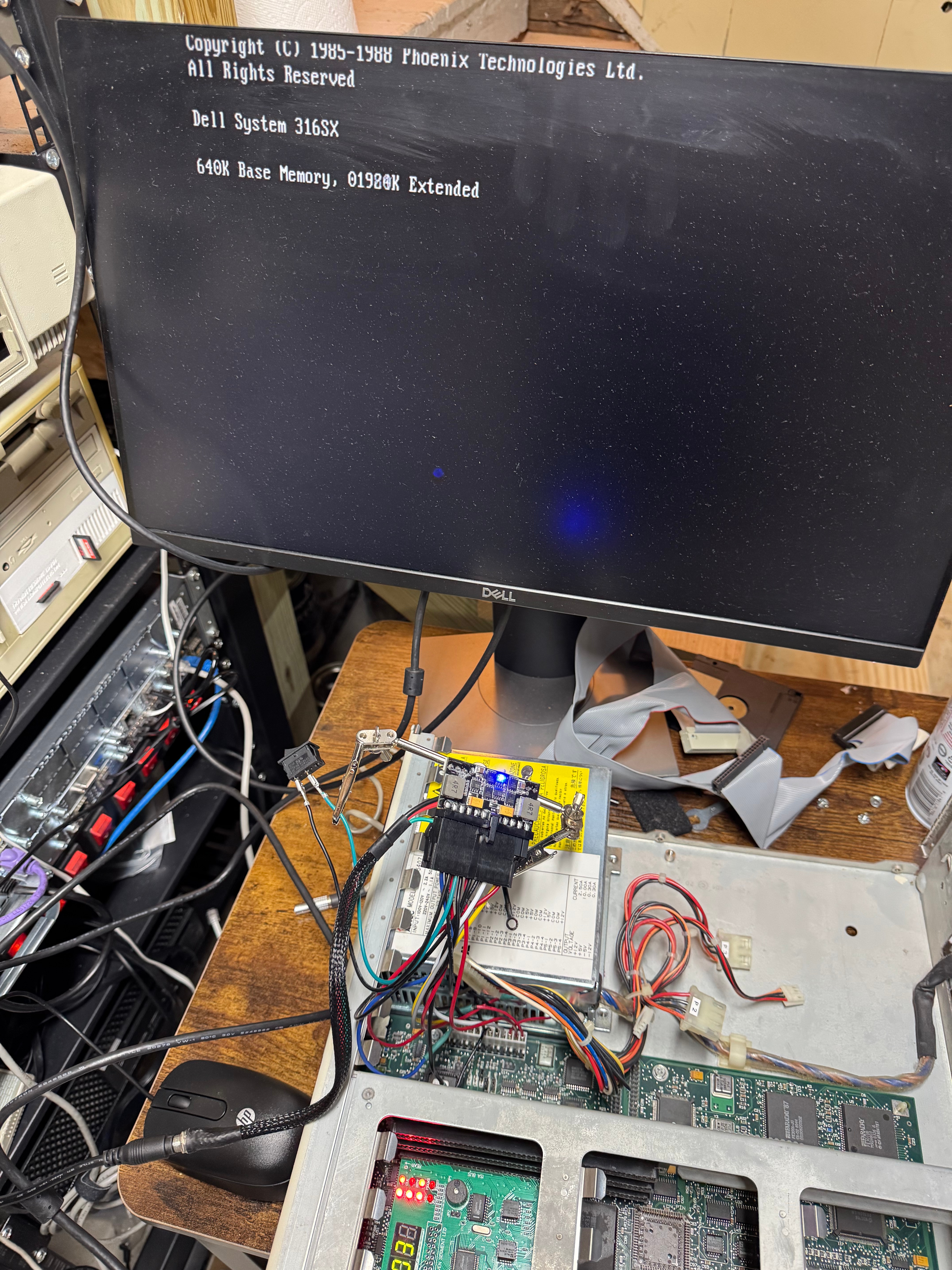
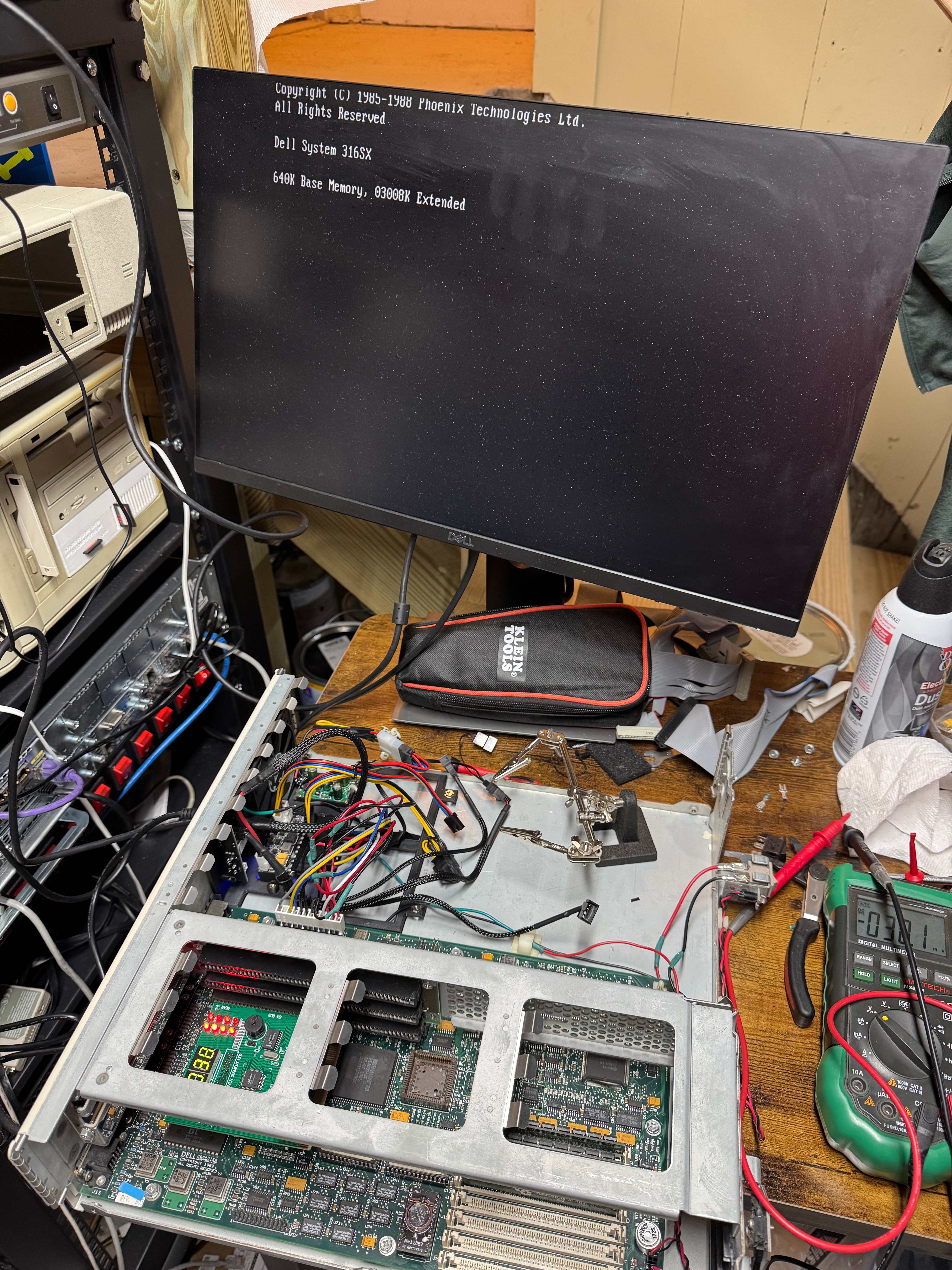
Then I plugged in just the motherboard, and with the power supply held in a little soldering clip, hit the power. And the system came up! Well at least I got video with the BIOS showing up! Plugging in the diagnostic card I saw +12V, -12V, +5V were all good, but the card said 3.3V was failing. That’s odd, 3.3V is not a voltage I provide. Turns out the motherboard uses the -5V rail to create the 3.3V rail. Searching online shown that -5V wasn’t really needed for anything, but its part of the ISA spec and some Sound Blasters and network cards need it, which means I wanted to have it. It’s worth noting this rail is used in very little quantities, the original power supply had .30A for the -5V line max. While the ATX standard mentions -5V, its not longer used in modern PCs. Thus, no modern power supply tends to give out the -5V. I got a step down converter that can do negative voltages and stepped -12V to -5V. Wired that in line, and I suddenly had all the power rails I needed!
First sketchy bootWide shot of sketchy bootCable messCleaner cablesClose up of powerPSU and POST cardCleaned up cable areaTaping down cables
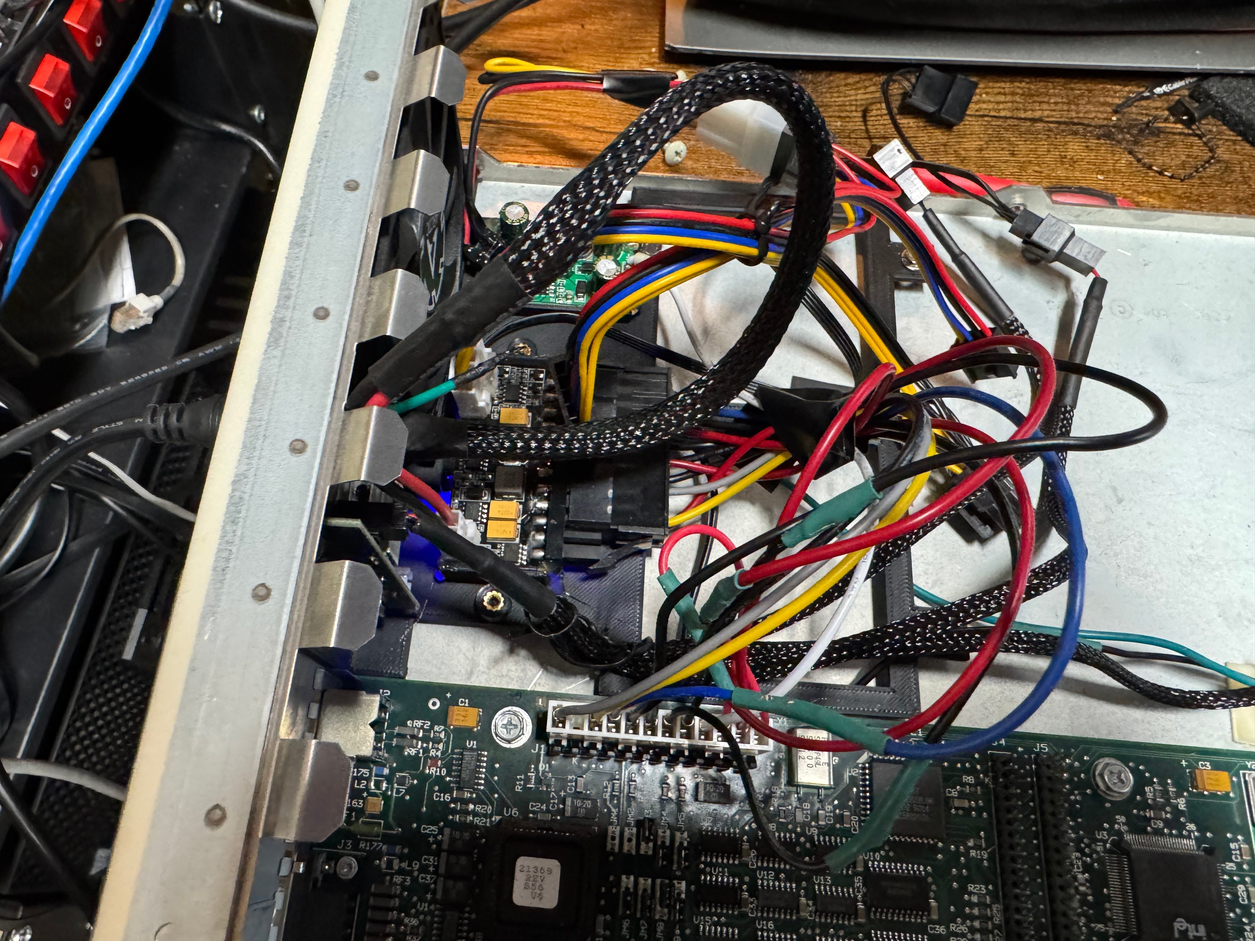
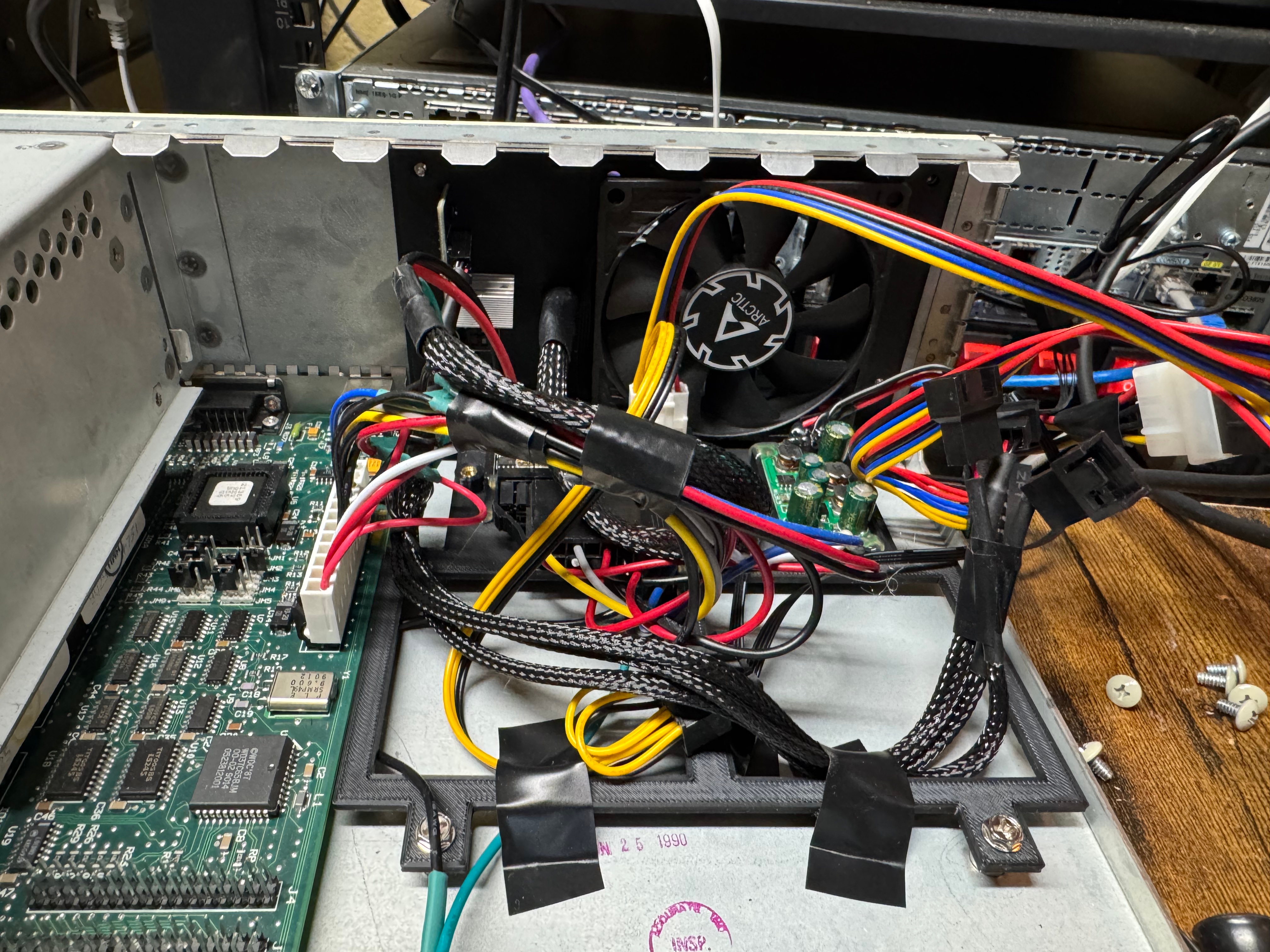
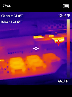
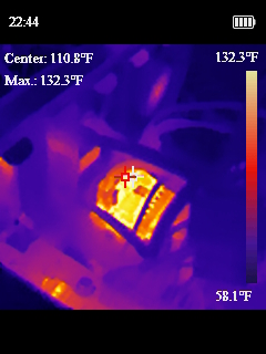
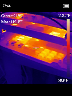
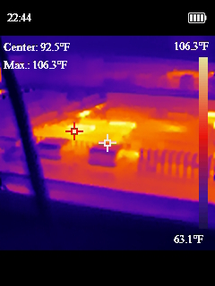
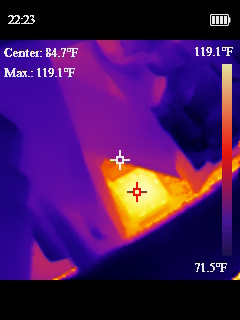
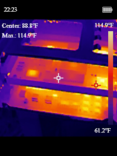
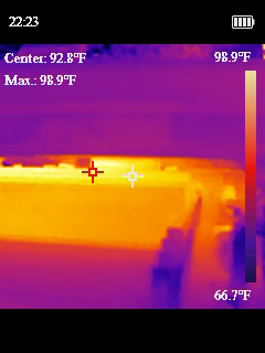
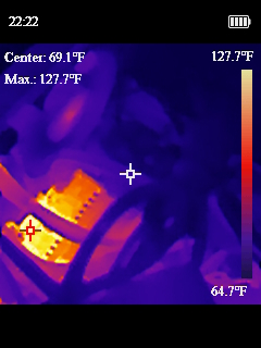
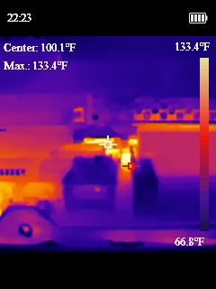
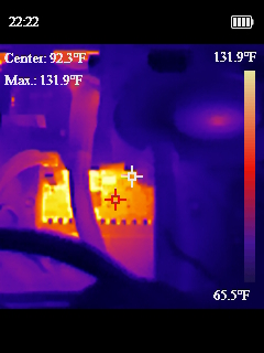
Now that we had our semi-sketchy power situation working, I wanted to design a bracket to drop in where the old power supply went and could hold all these pieces nicely in place. I ended up working on a cover to mostly protect myself from the open PicoPSU running at the heart of the system. I added a fan with a speed controller as well, since the original power supply fan in the system was the only airflow the whole computer has. Then I added another fan to the front of the chassis. The system originally only had the one power supply fan, and when I took thermal measurements some of the chips were getting toasty and I thought another fan couldn’t hurt.
Extra FanExtra Fan
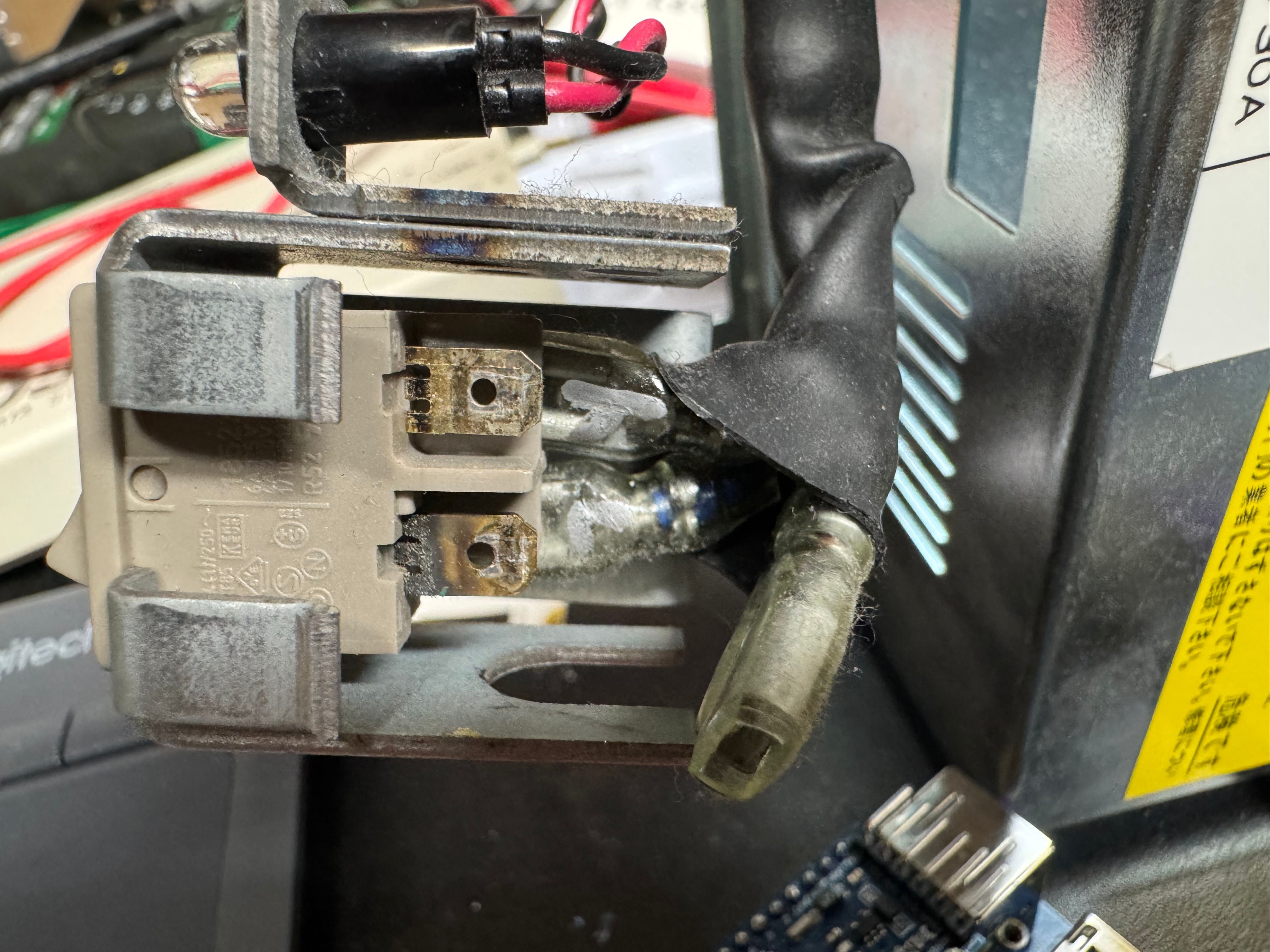
One last fun fact about this old power situation. The old computers didn’t have “soft power” like we do today; where you hit on and it tells the BIOS to start booting. This system had a big ON/OFF switch in the front with mains voltage (120V for the US) going to it. In replacing the PSU, I swapped this for a ATX, low voltage on, switch.
Front switchNew power running to front switch
Video
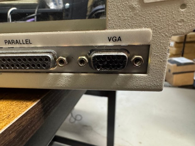
While the Dell 316SX does have standard VGA on the back, there is not a spot for pin 7; the second pin in the second row. If you lookup pinouts for VGA online, this pin is either called “green ground” or “not used”. These days even if not used we include a spot or pin for it and not connect it. This machine has no spot for a pin. I had to get a VGA cable, and cut the pin out; allowing the cable to plug in.
Data Recovery
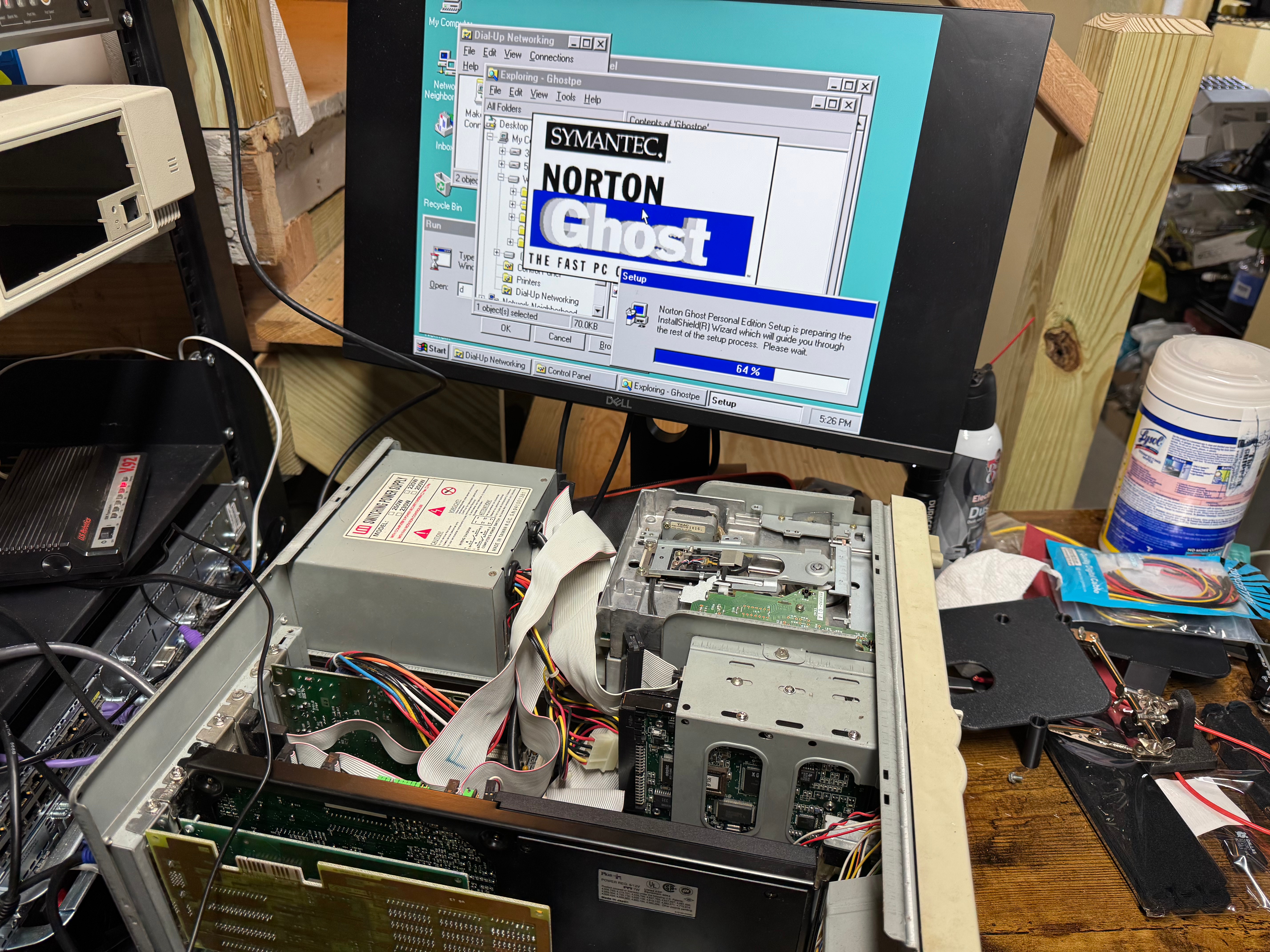
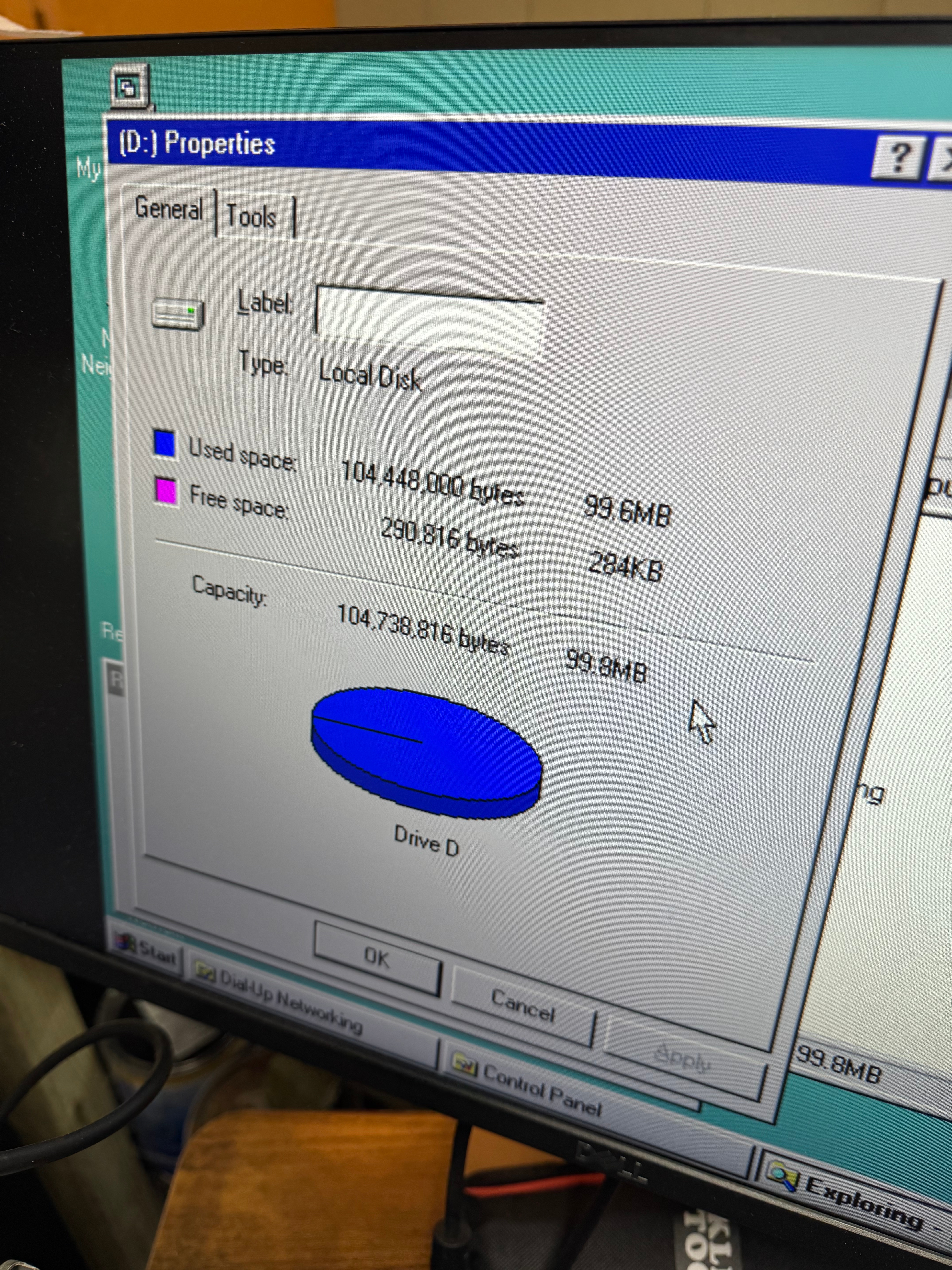
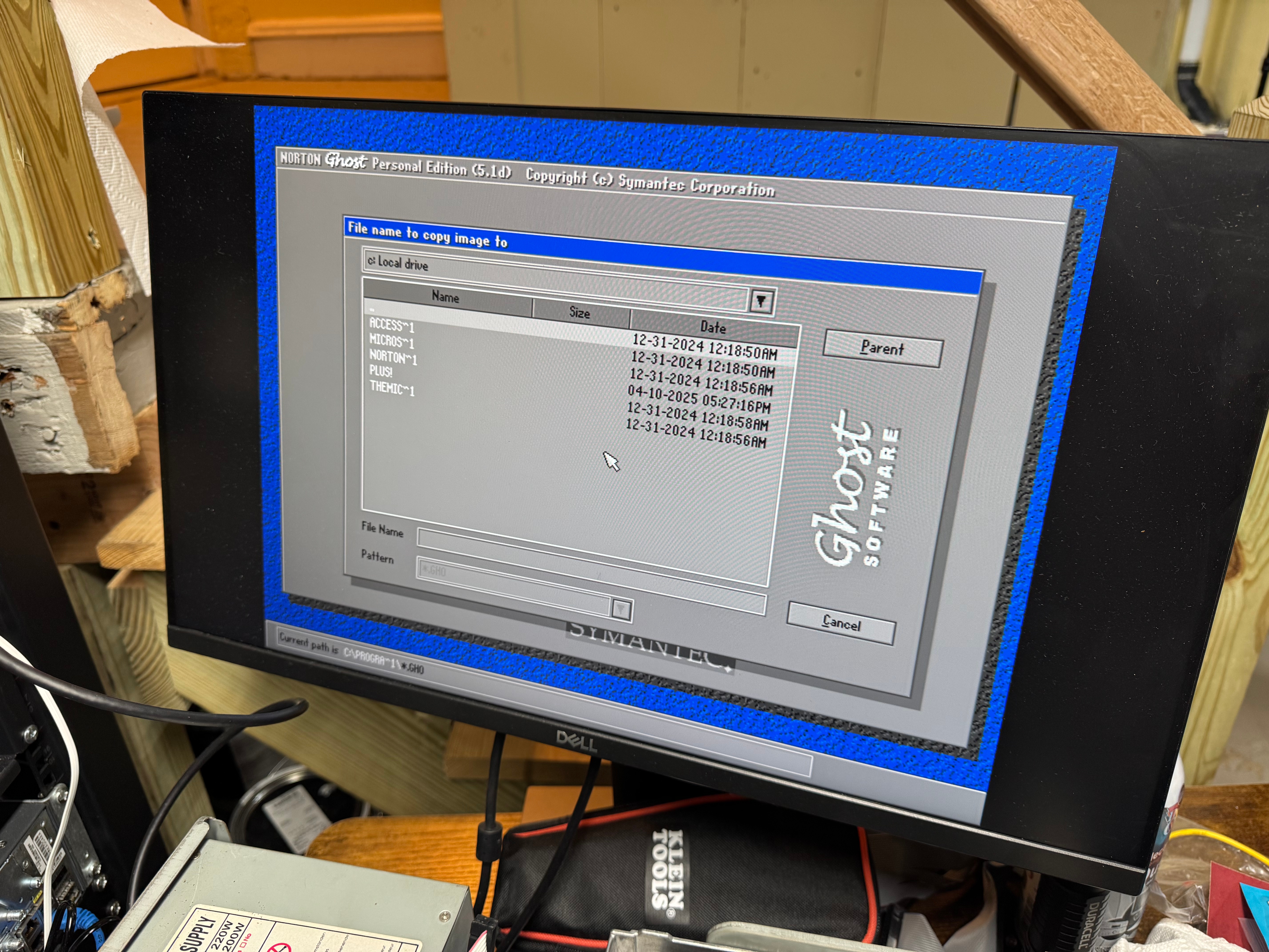
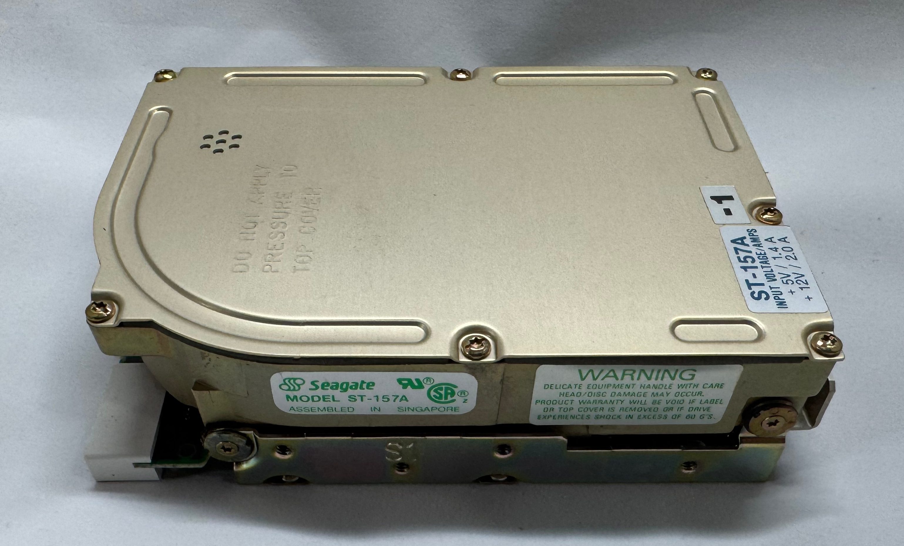
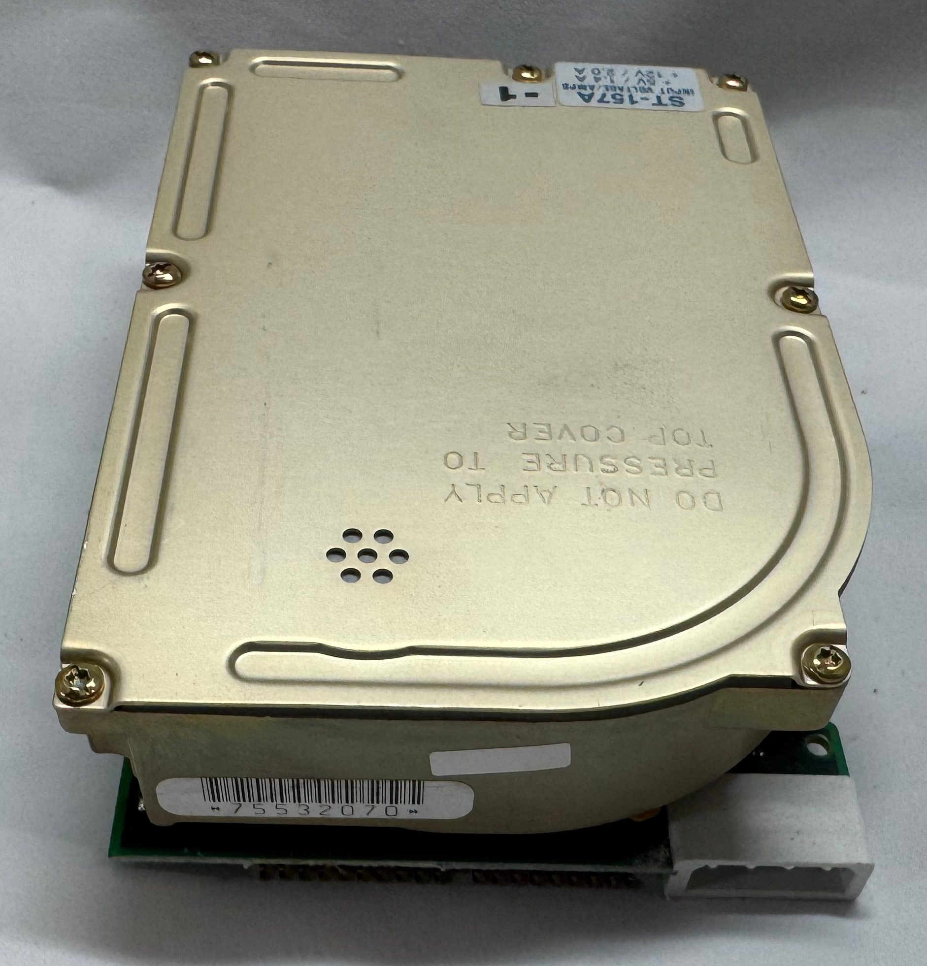
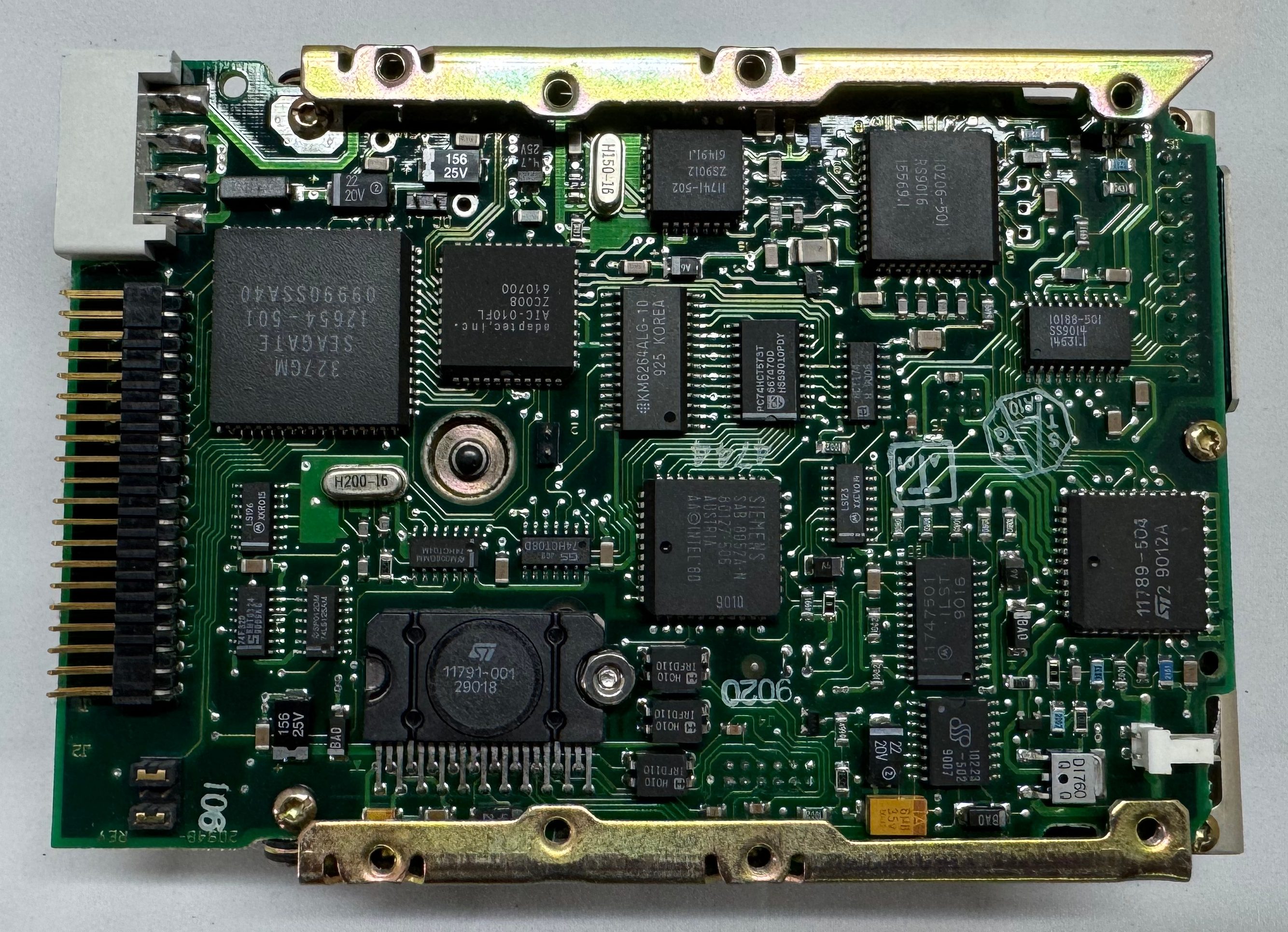
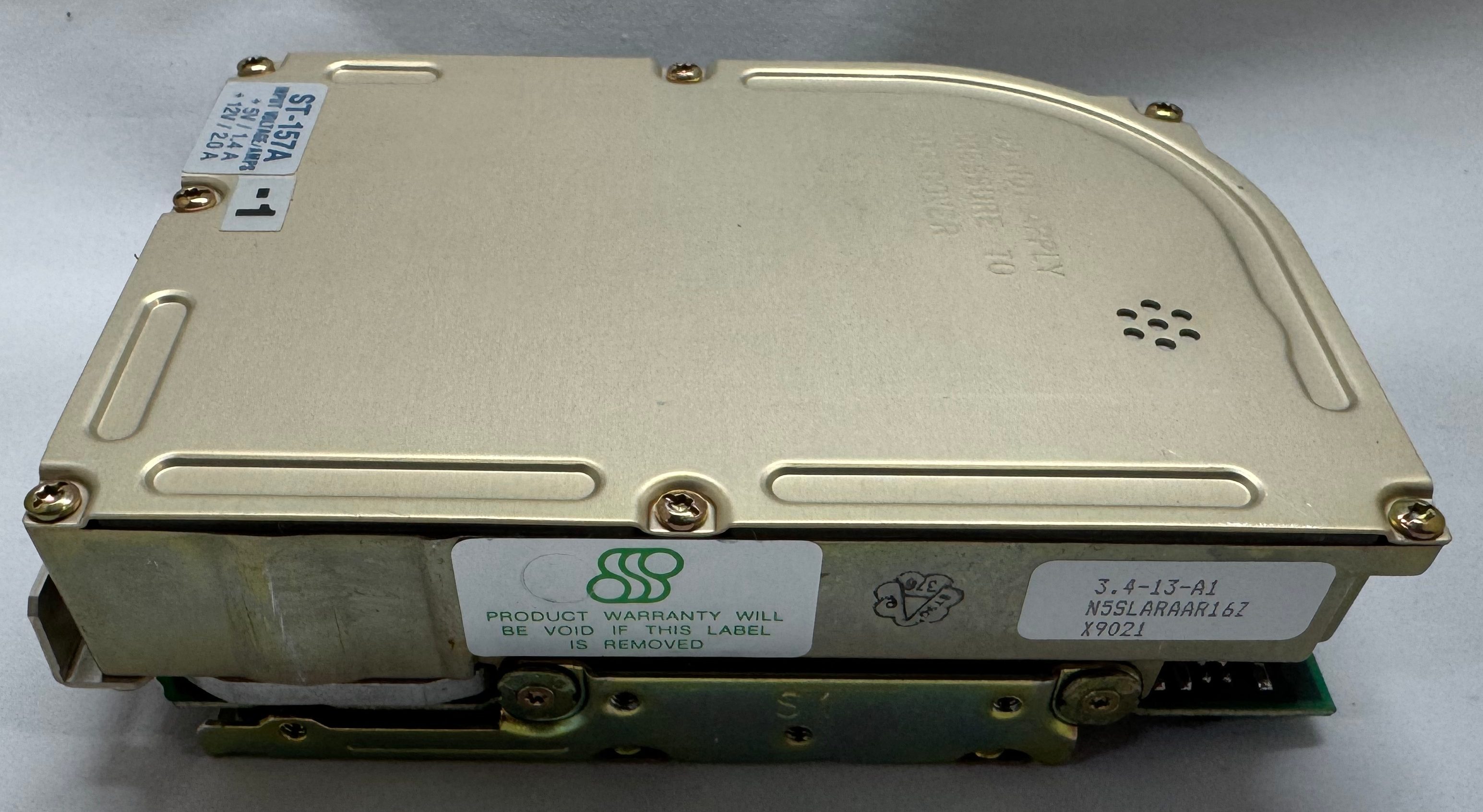
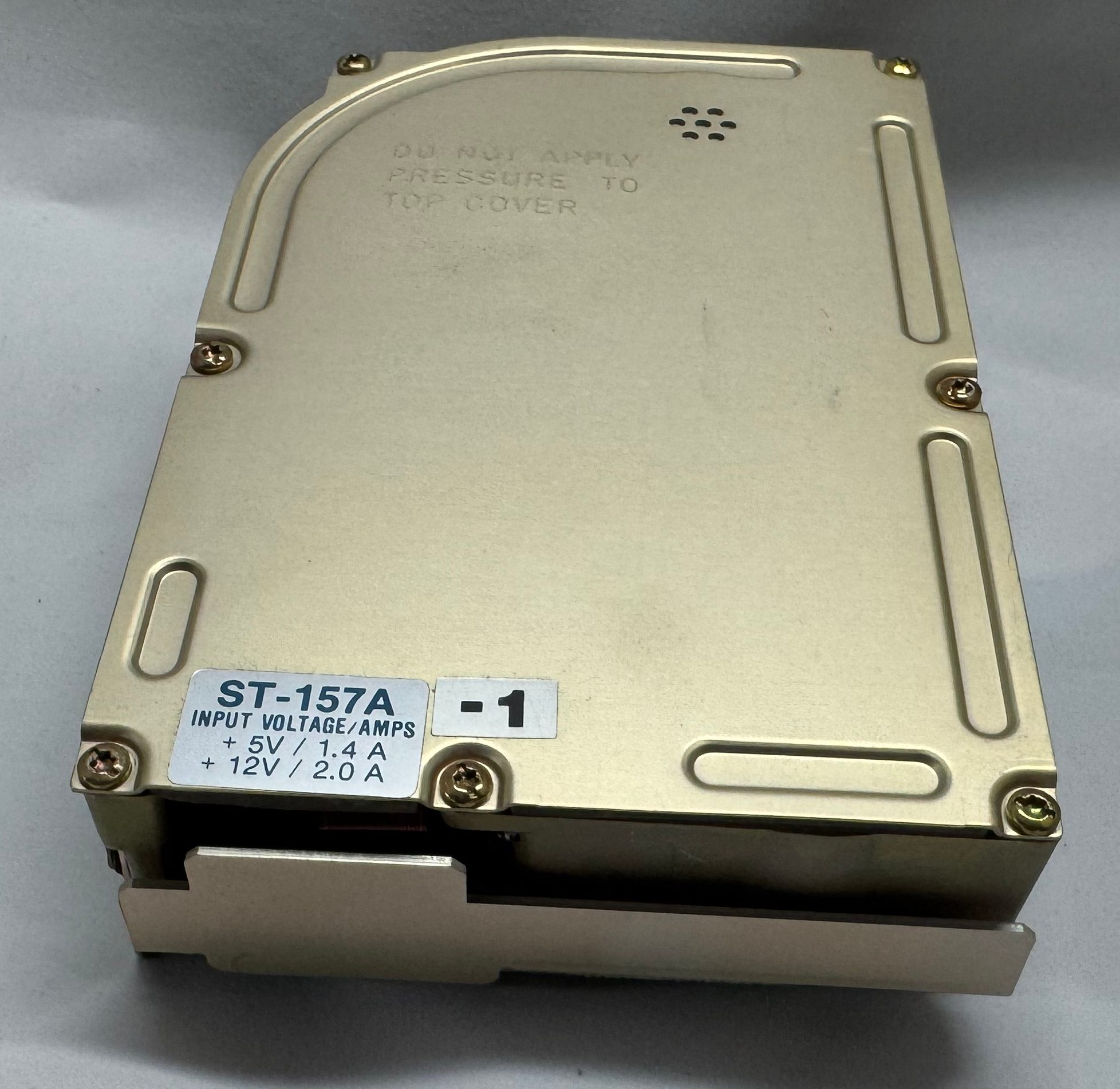
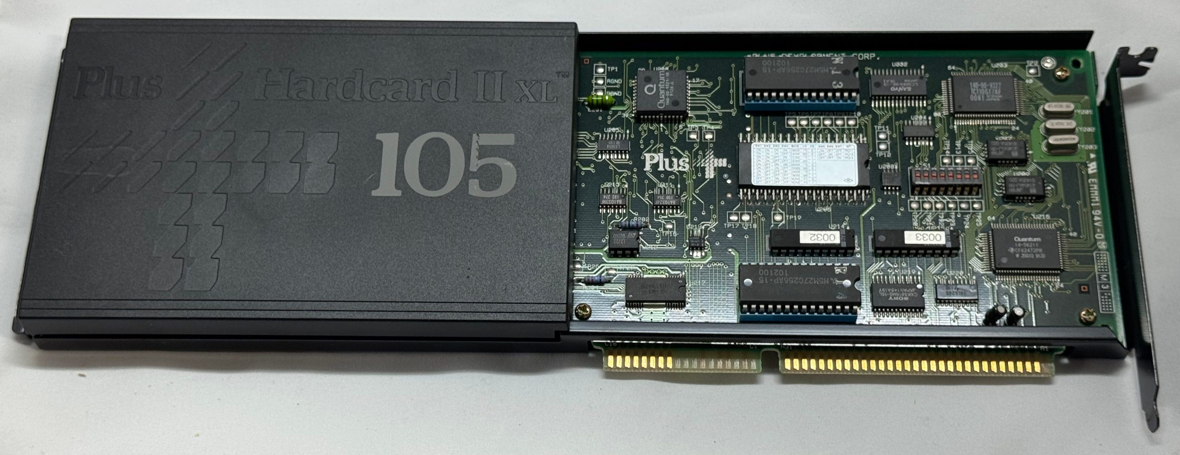
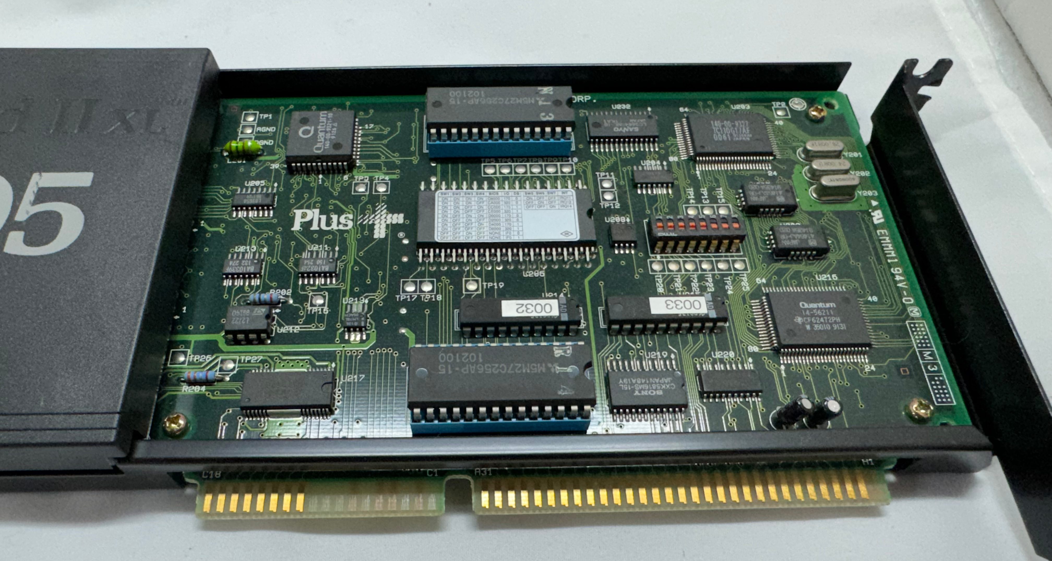
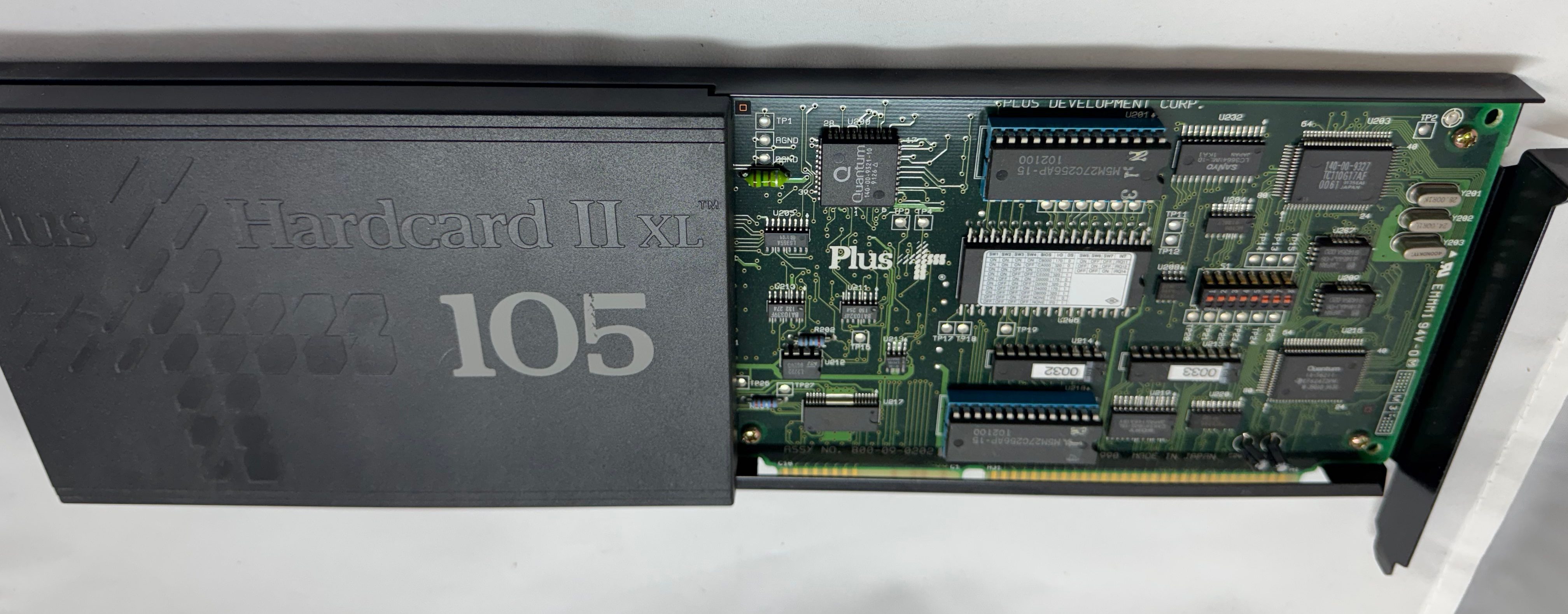
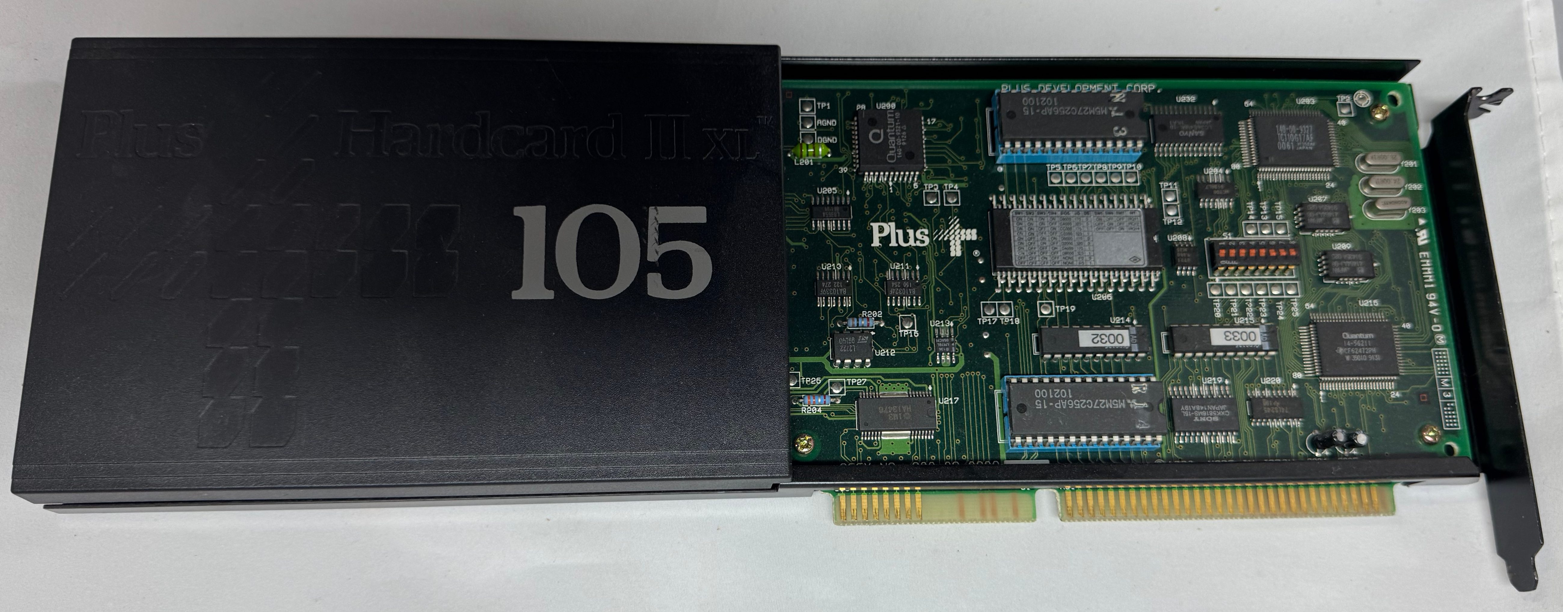
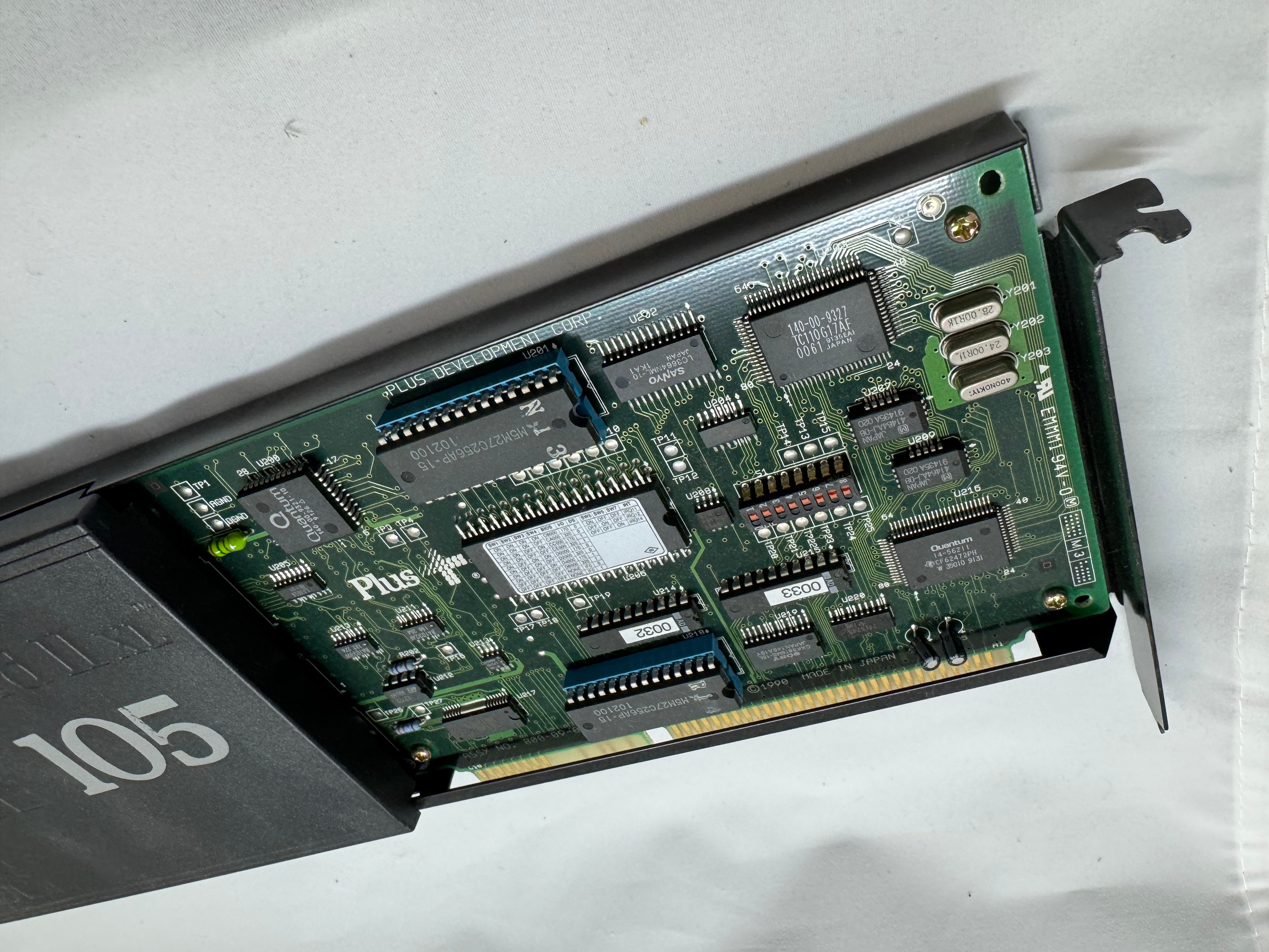
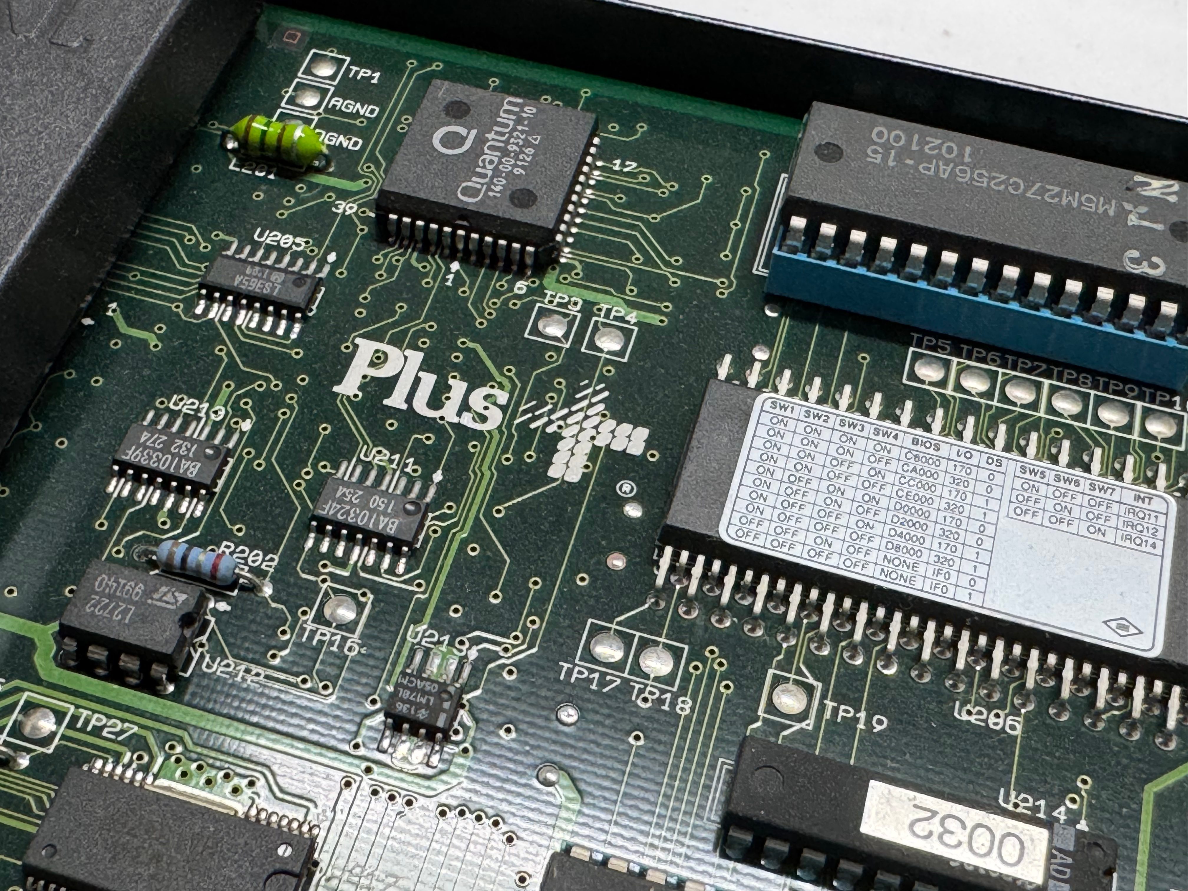
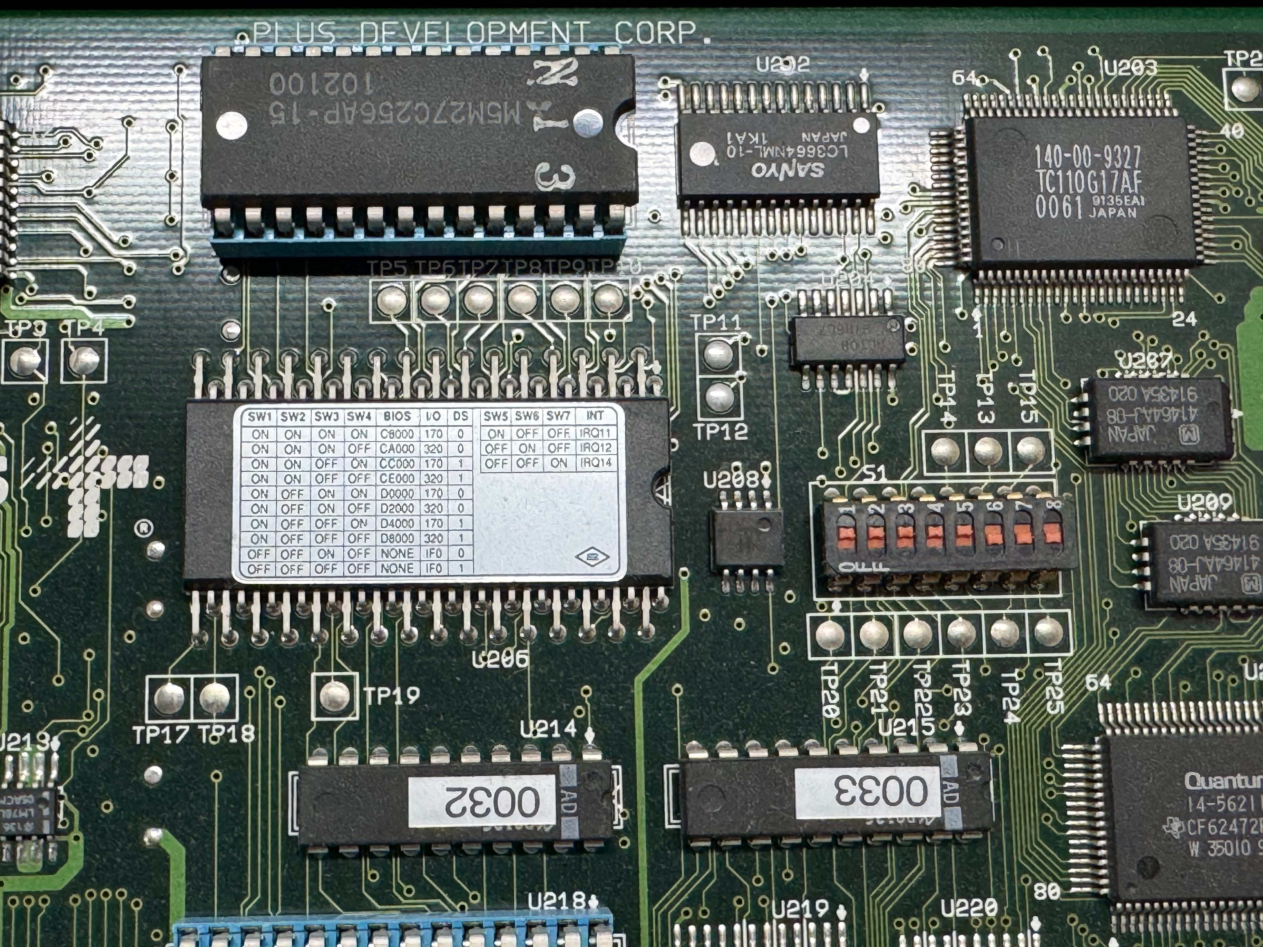
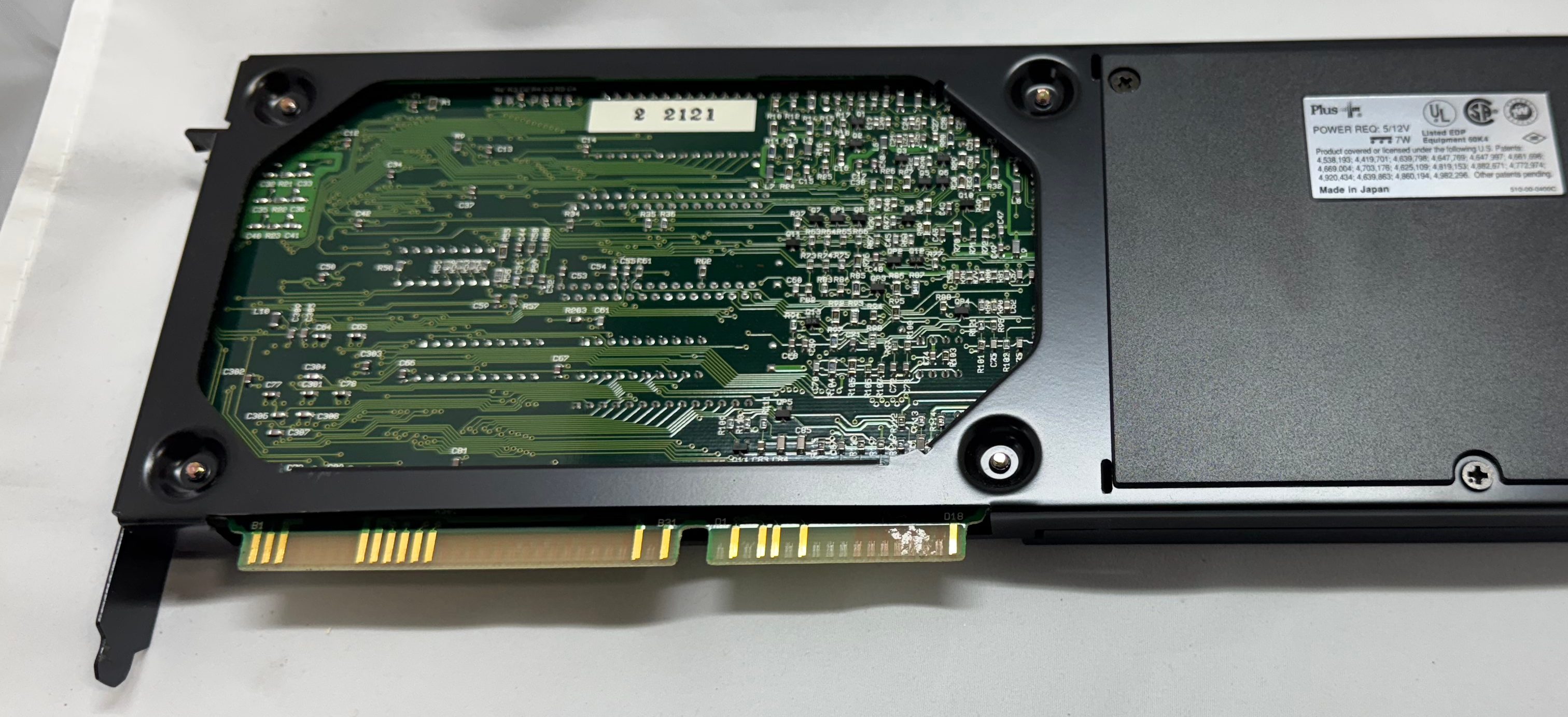
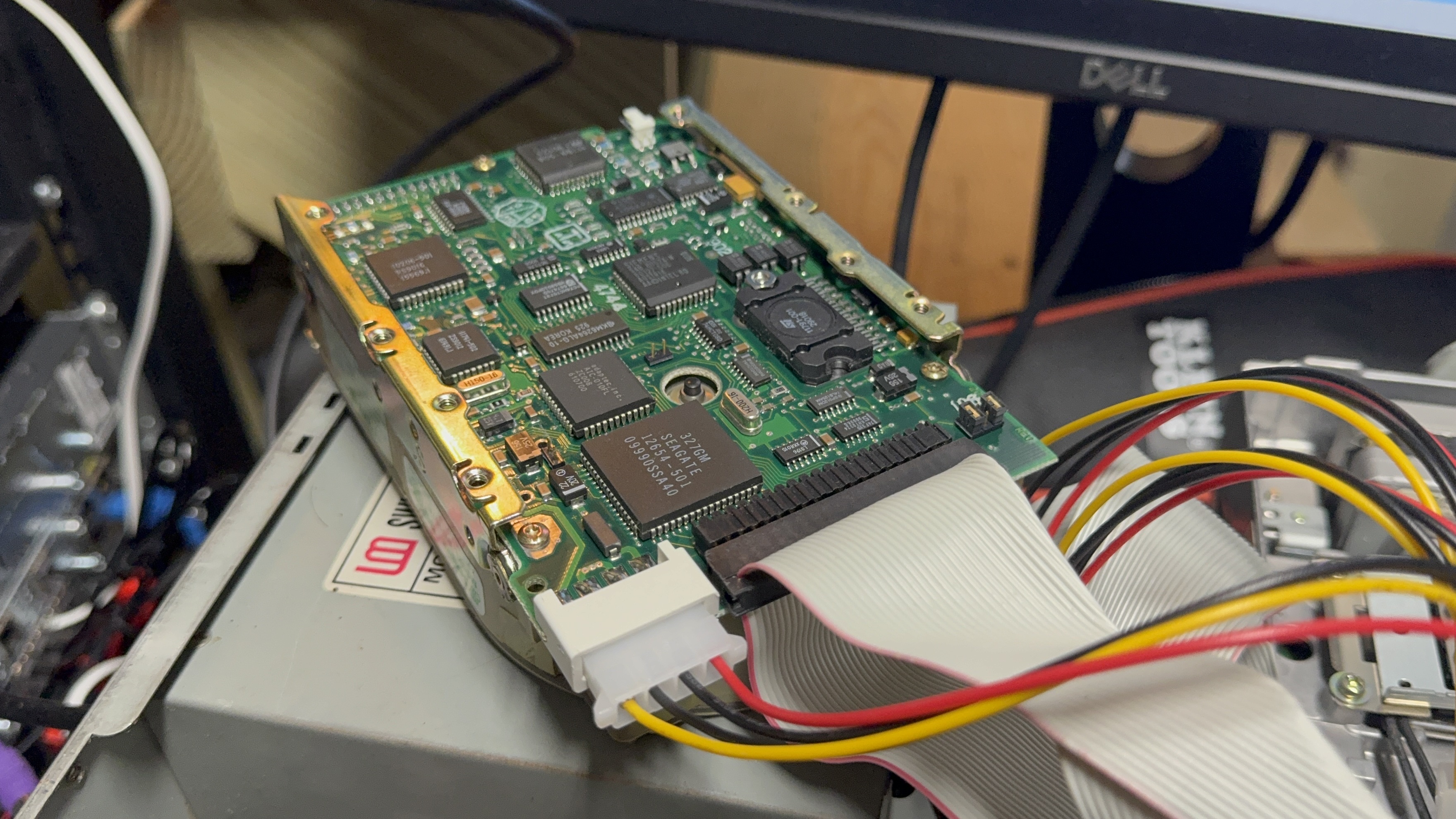
Now we had power, and can POST. The Dell 316SX had a Seagate ST-157A-1 – 44MB IDE/ATA-1 HDD; and a Hardcard II XL – 100MB ISA card. The first thing I wanted to do was get a backup of each of these storage devices just in case after 35 years they suddenly died. The Hardcard was easy, I moved it over to the 486 I had, used an old copy of Norton Ghost, and captured the drive no issues.
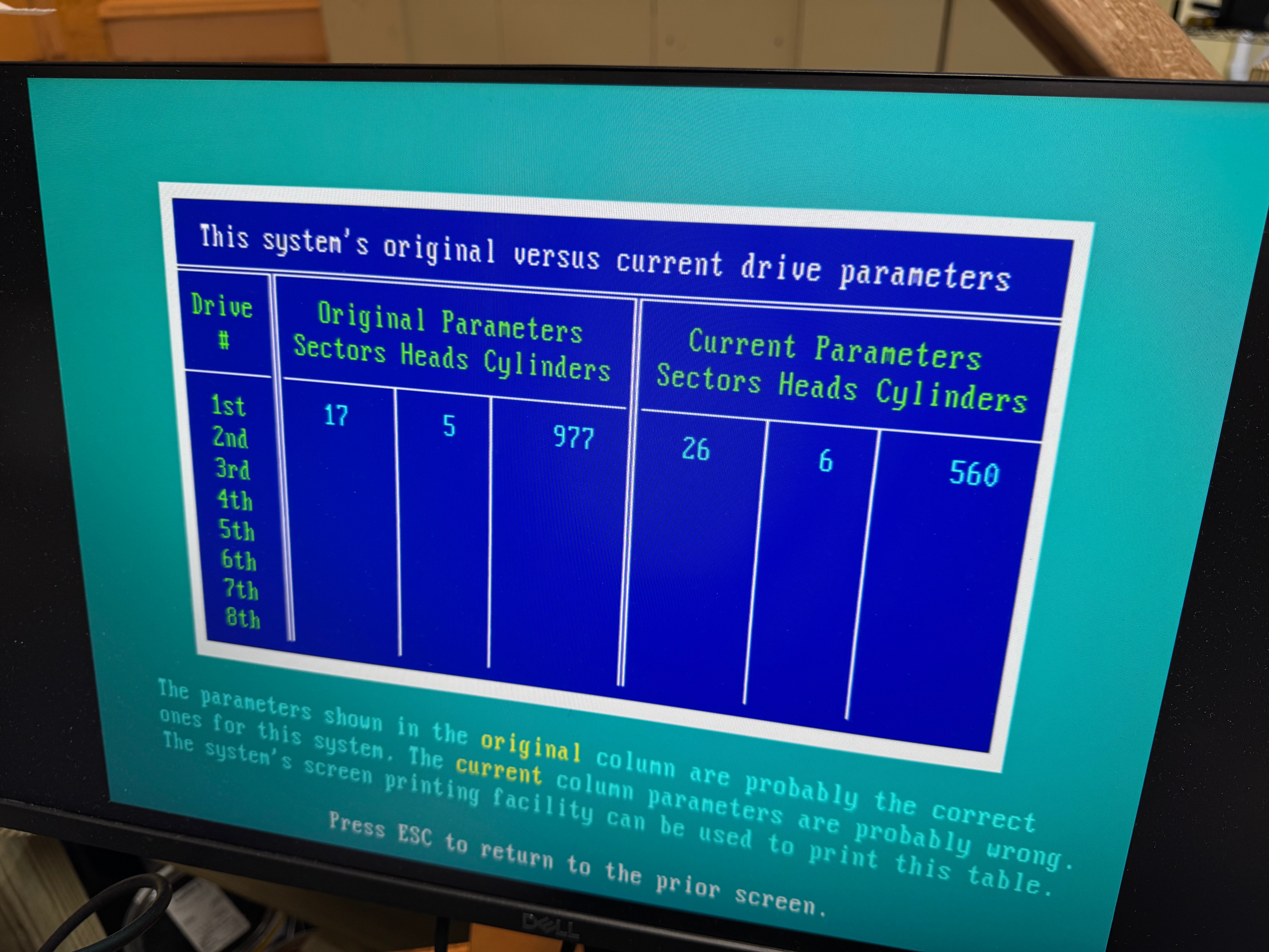
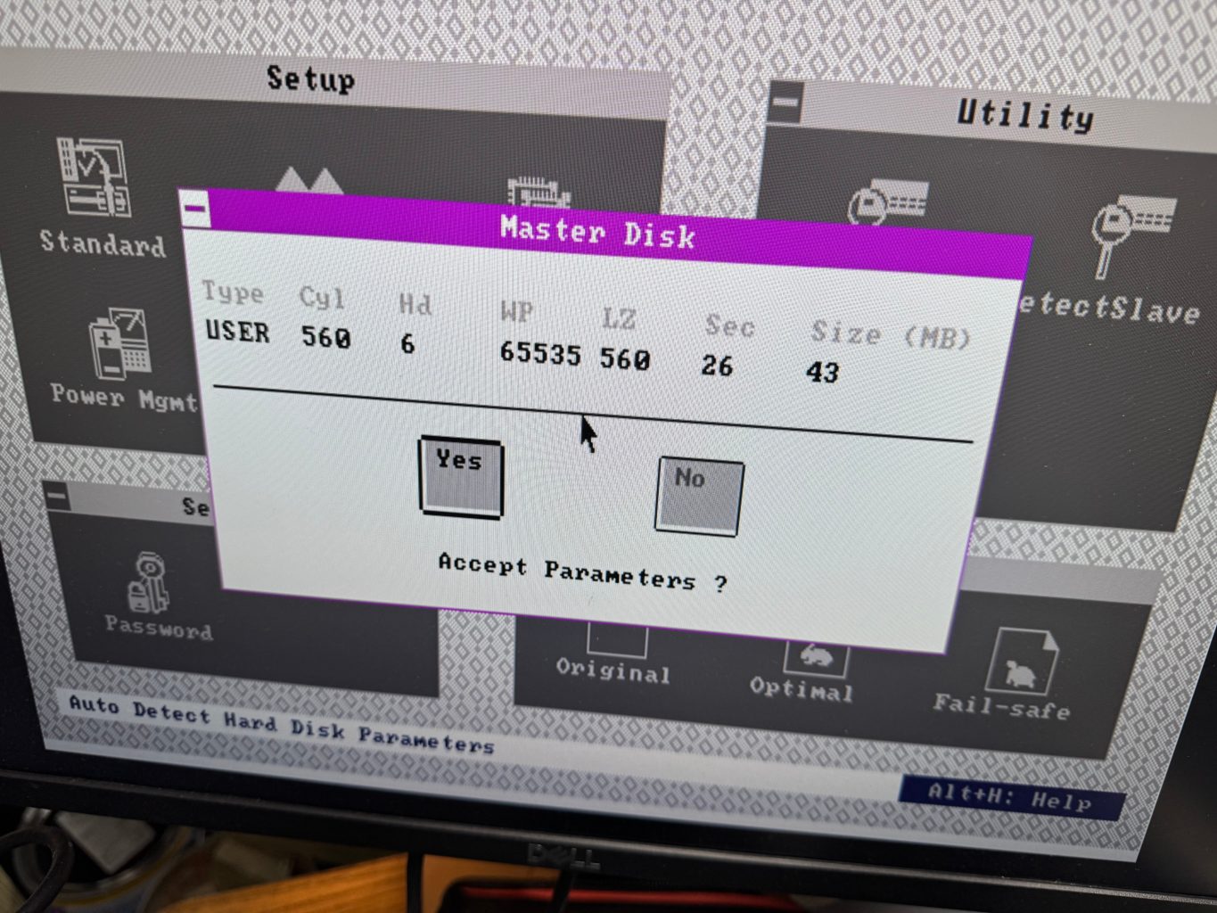
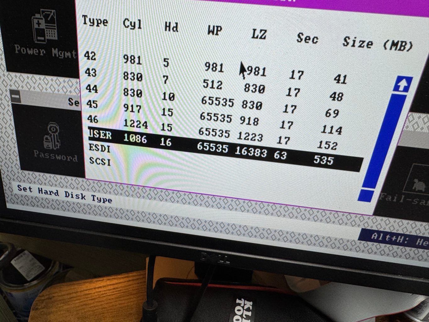
The hard drive was a bit harder since the 486 is old enough it can only have 1 drive on its primary IDE channel; that left the secondary channel. In trying different setups I realized that the Dell 316SX did not have the correct hard drive parameters entered when it was in use. This means, when I tried to read it on a machine where I couldn’t set those settings, I wouldn’t get the correct data back. I HAD to have the disk read from the primary 486 IDE channel where I could edit the parameters to be incorrect on the 486 like it was on the 386. I got an ADAPTEC AHA-1542CP ISA SCSI CONTROLLER (from this seller), this allowed be to boot a DOS floppy, load Ghost, and image the drive to the new SCSI device, with the correct – incorrect hard drive parameters. This SCSI card has a full BIOS on it, allowing DOS to reference and even boot off of it without a driver.
The true savior here was Spinrite. I didn’t realize the hard drive parameters were causing my issues, and I thought the drive had just died. I figured I would give one last shot with Spinrite before calling the drive dead, and the data lost. Before I could start a scan, Spinrite popped up saying that the drive wasn’t recorded correctly and I should edit those settings!
Spinrite to the rescueSD Card params on 486Custom sizing the SD card adapter on the 486Installing GhostVery full HardcardGhost great UI
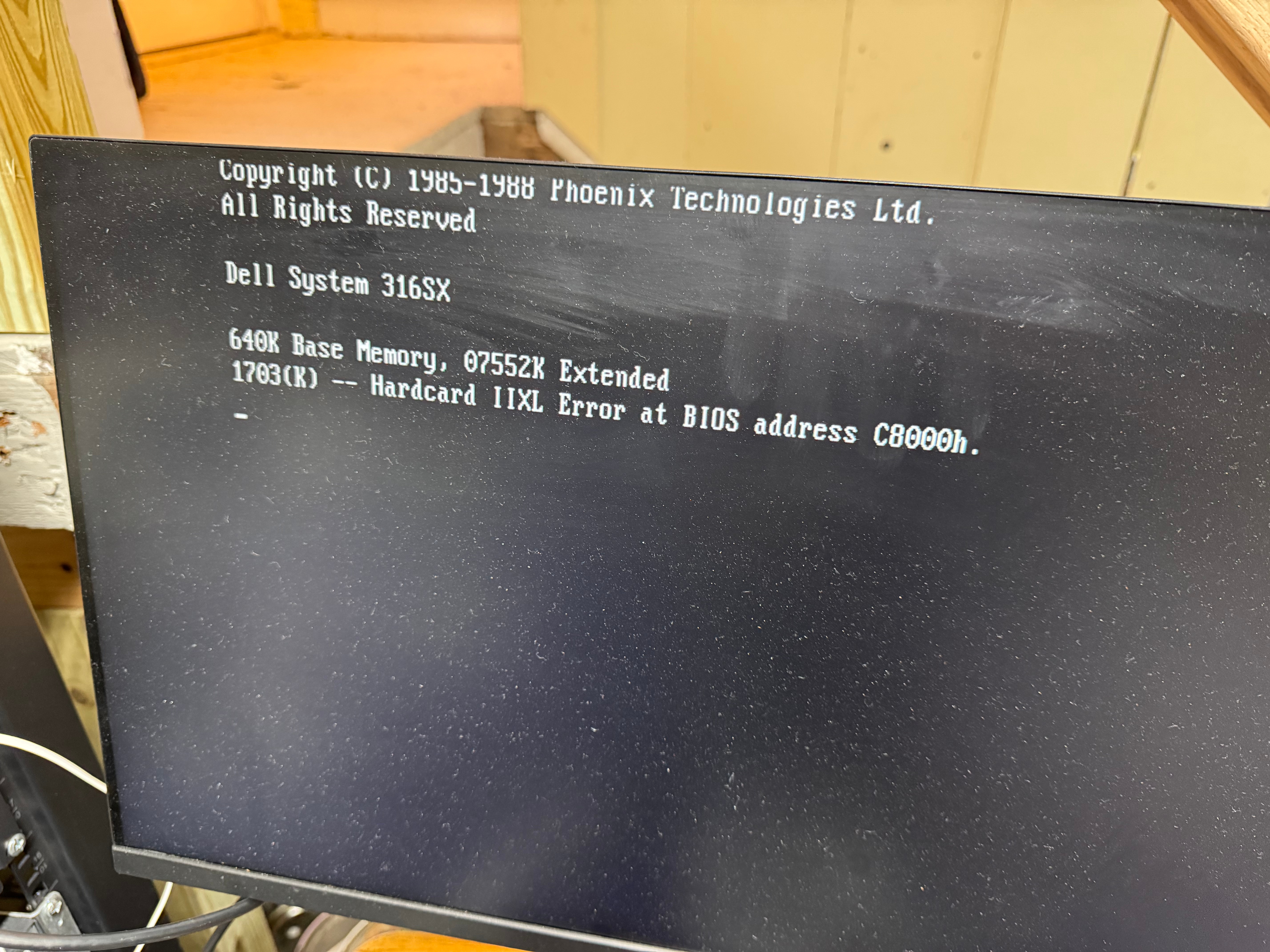
After capturing images of both devices, I started cleaning the system, taking some photos, and putting it back together. One last test of powering it up, and the Hardcard died. It would no longer POST, freezing when the card tried to spin up. I am very glad I captured an image while I could! I copied that image into an image for the BlueSCSI device I had, and we were back in business! The Hardcard started giving “1703(K) — Hardcard IIXL Error at BIOS address C8000h.” which the internet said was the drive had died.
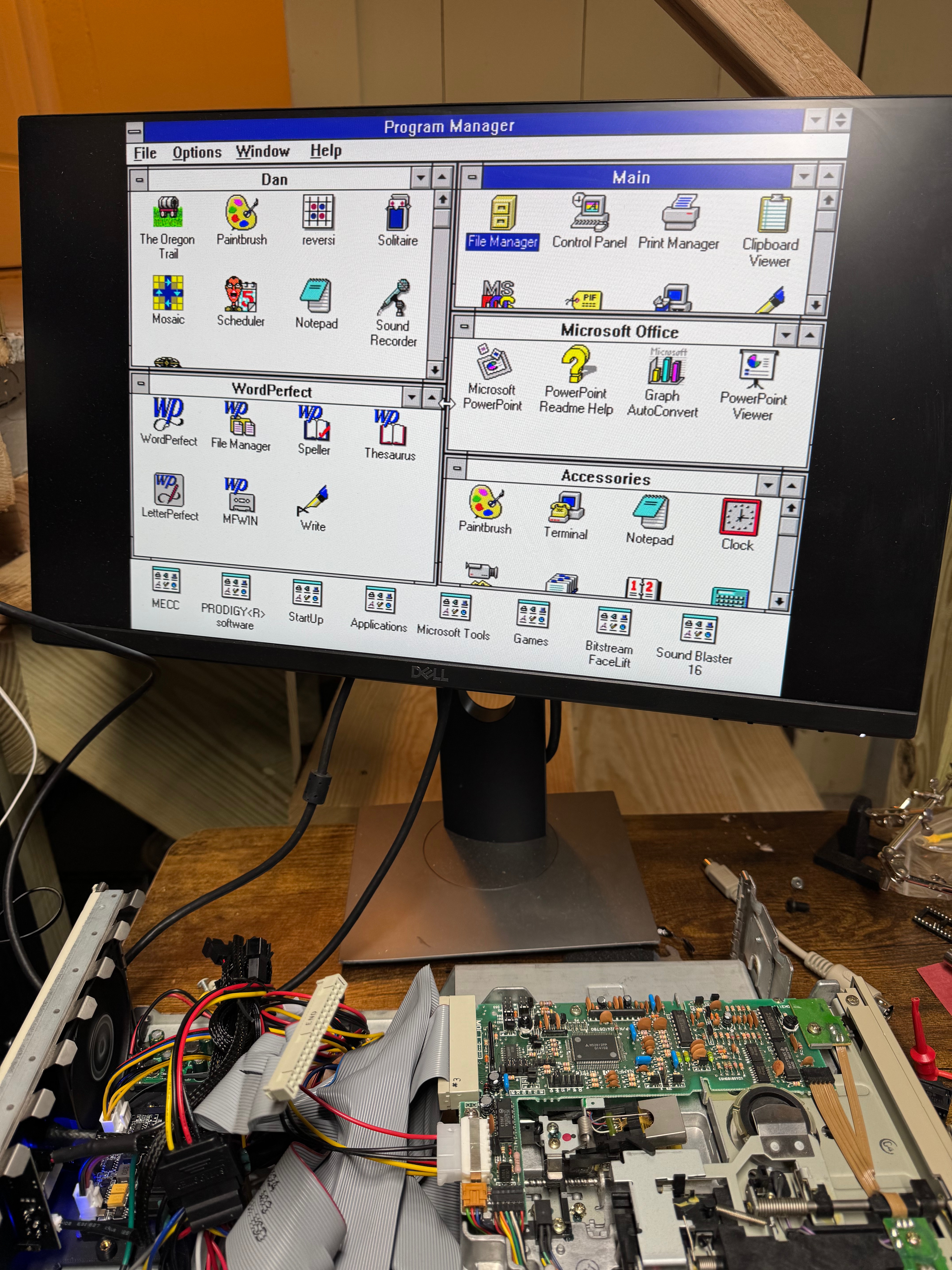
For those of us who haven’t done that much with MS-DOS in years, here is a reminder how partitions work (this is important because the old system had the Seagate drive as C and E, then the Hardcard as D); all Primary partitions that are accessible to the BIOS are added as the system boots, THEN all extended/logical partitions. This means, with the internal drive coming up as C: D:, then the Hardcard as E: I had to figure out how to switch them. In the end, it ended up being that the Hardcard was coming up as a extended partition, and it needed to be a primary one to force it earlier in the order. Turns out the Seagate drive had 1 primary, and one extended partition. After doing that change, and copying all the data back the system and all the links within Windows 3.1 came up correctly.
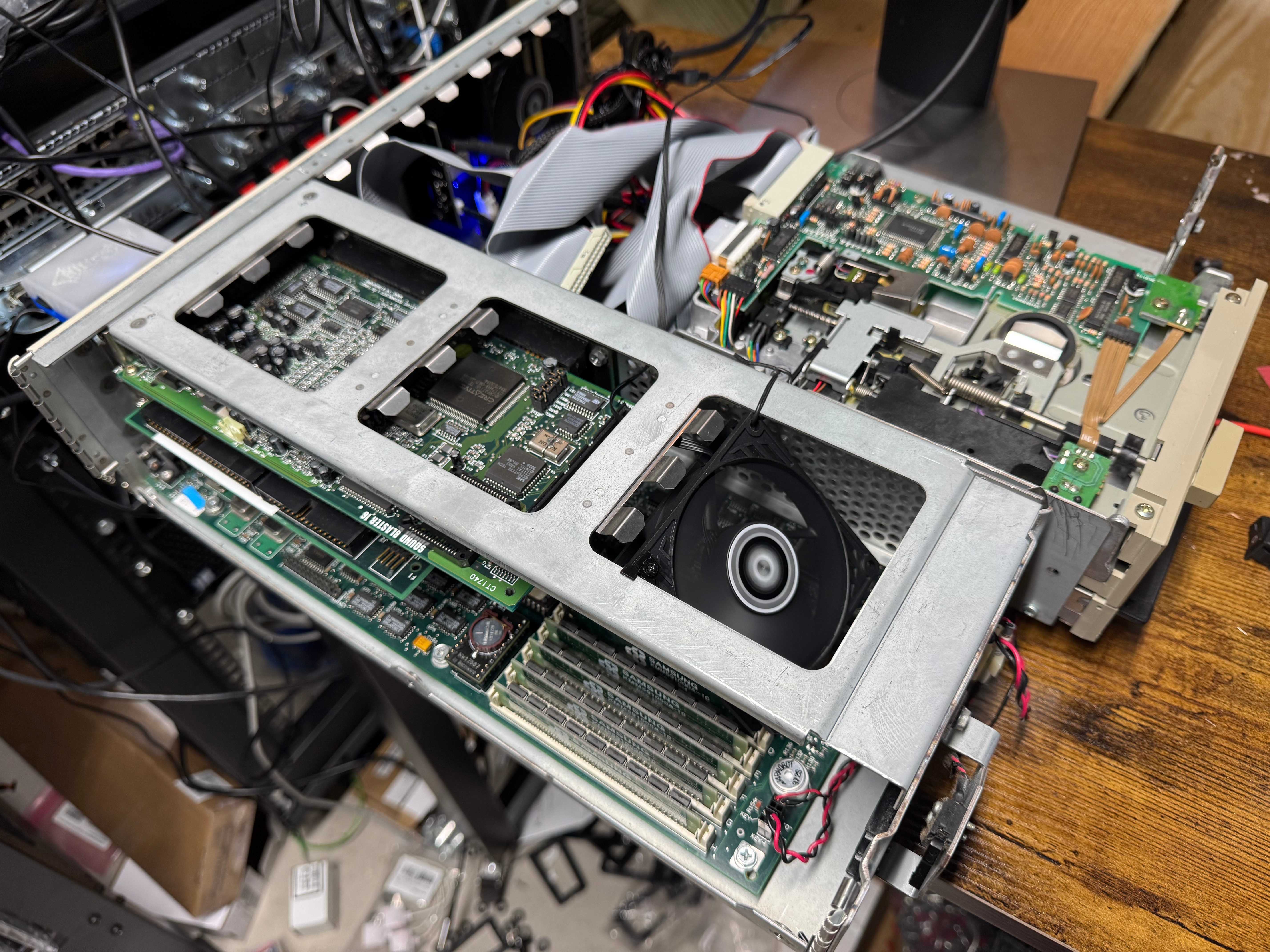
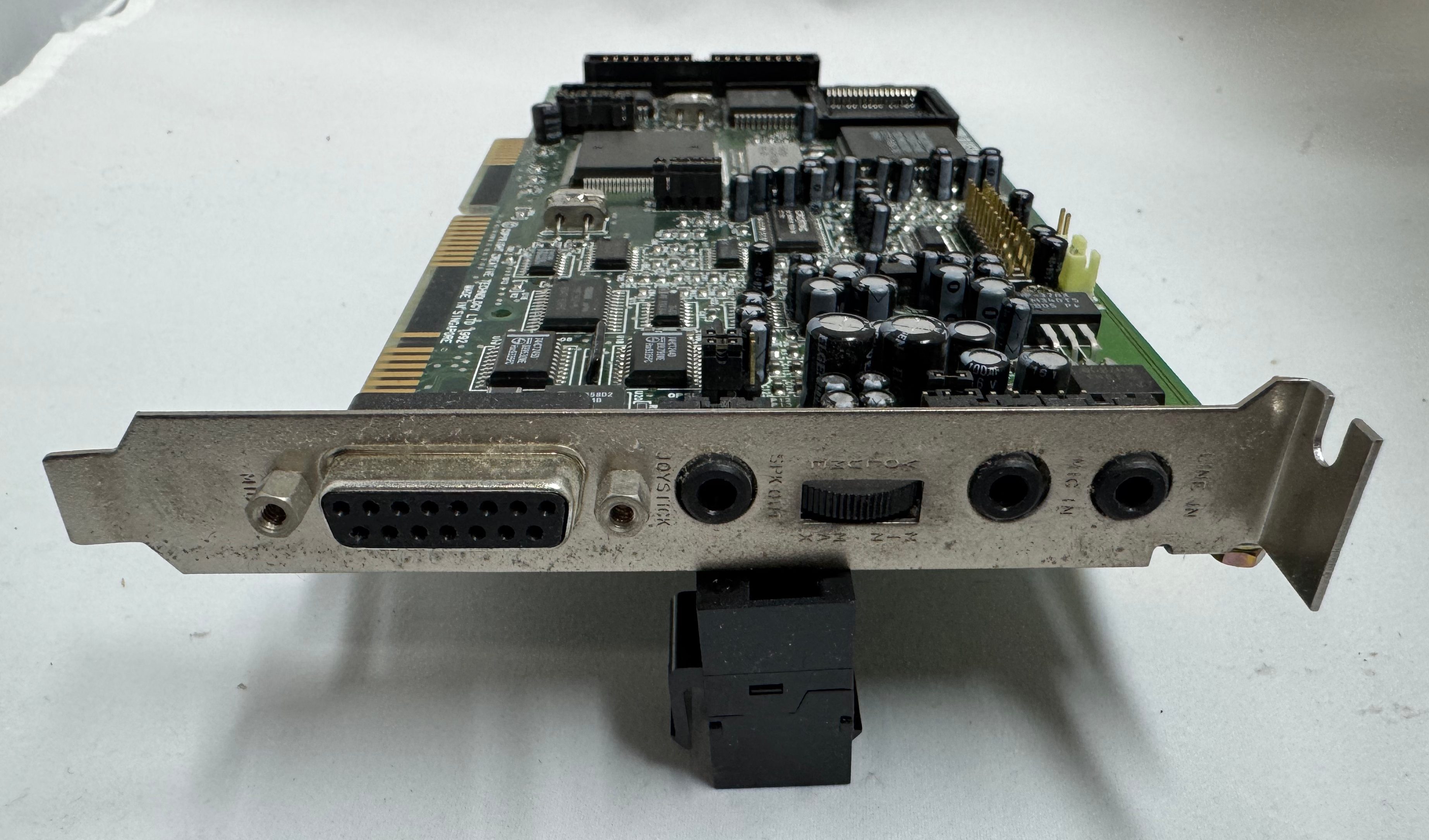
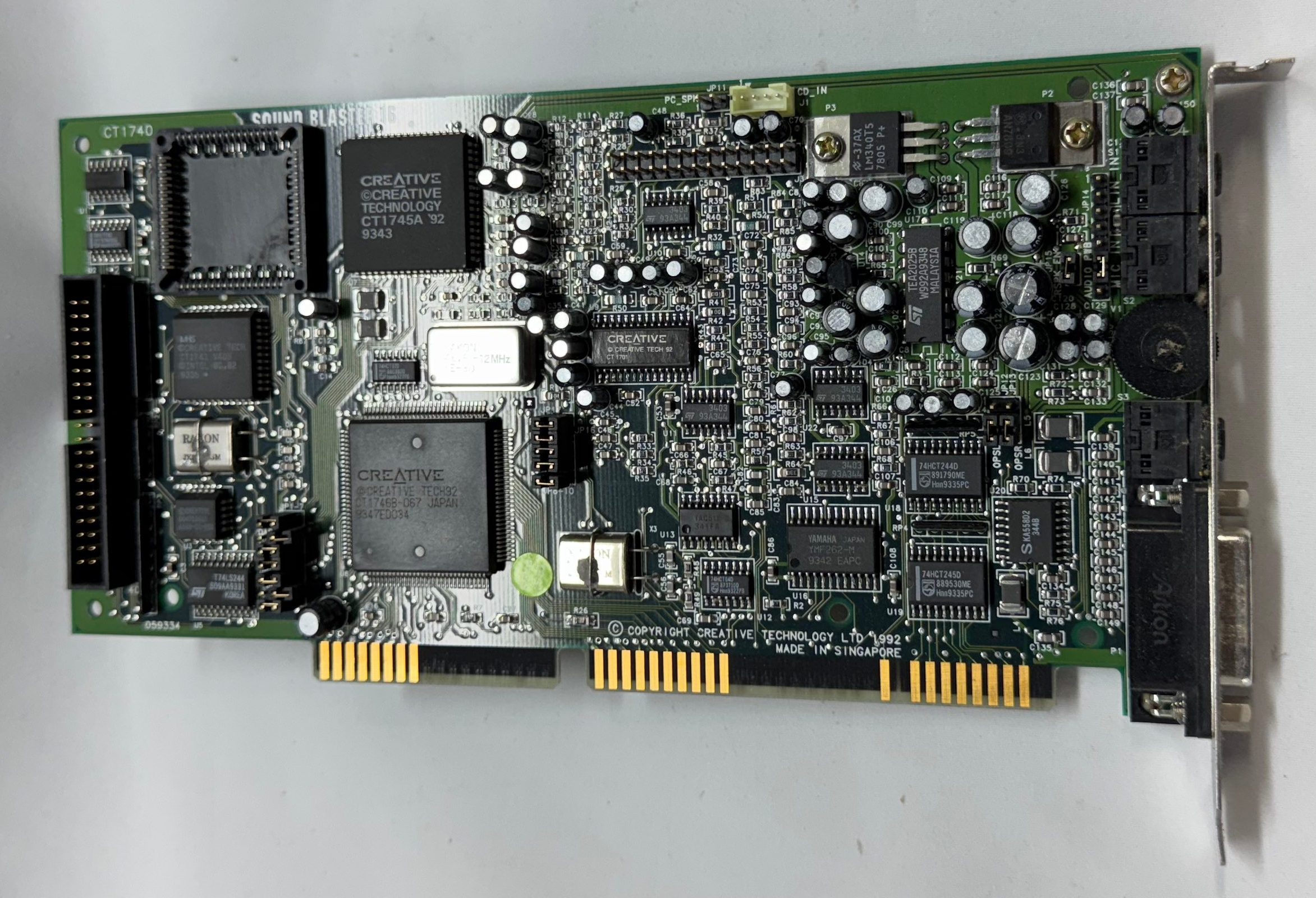
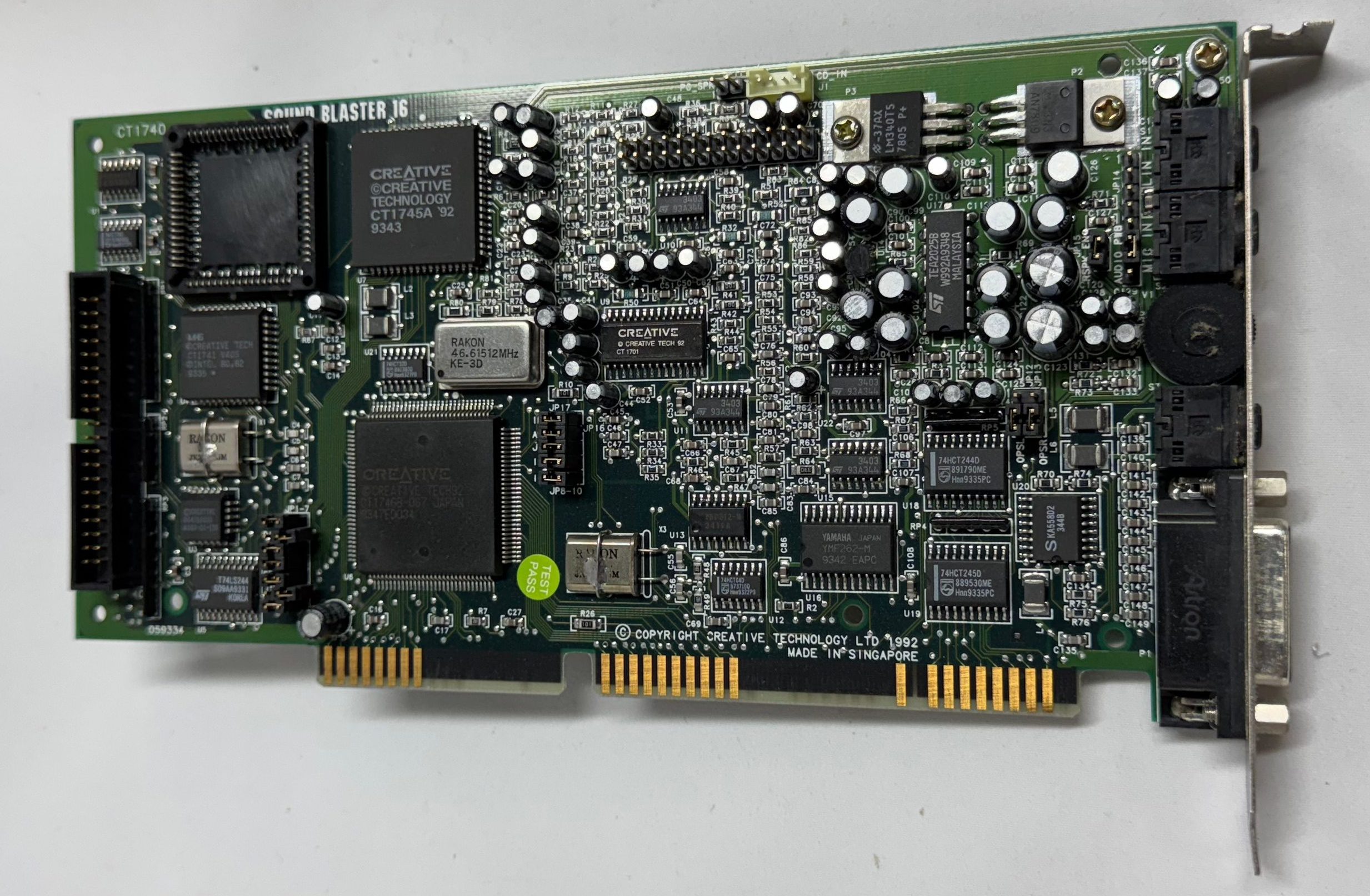
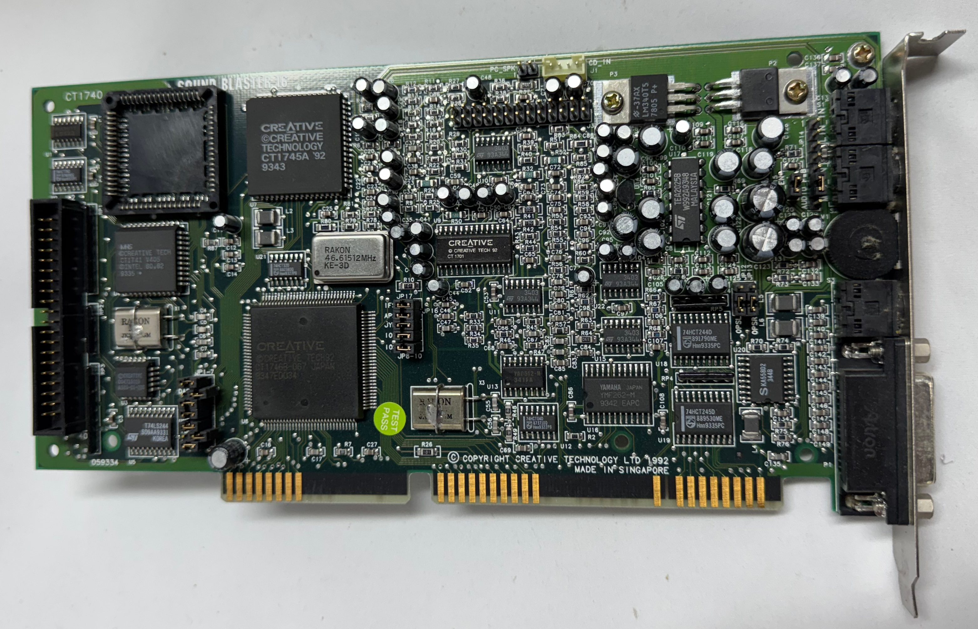
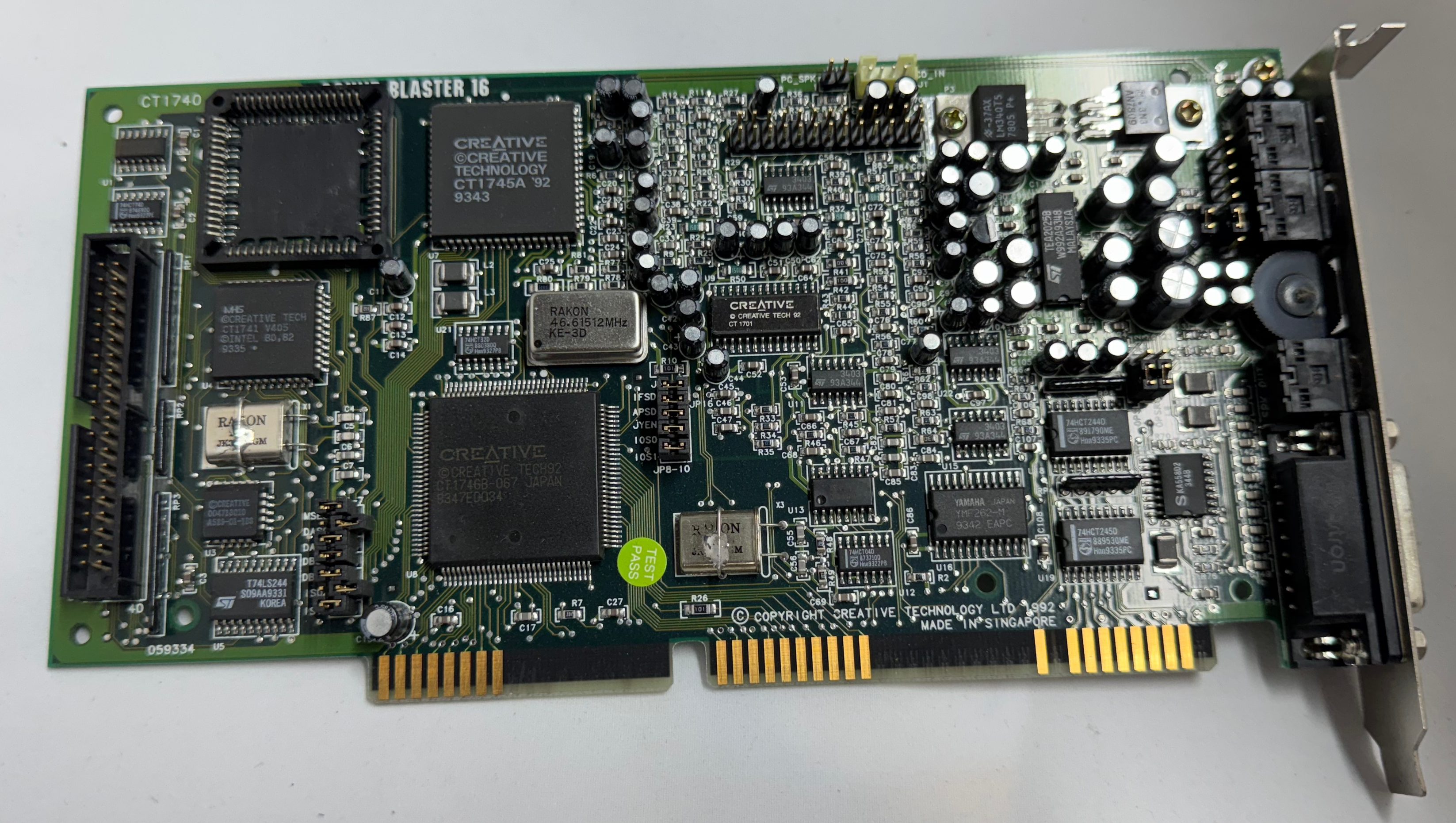
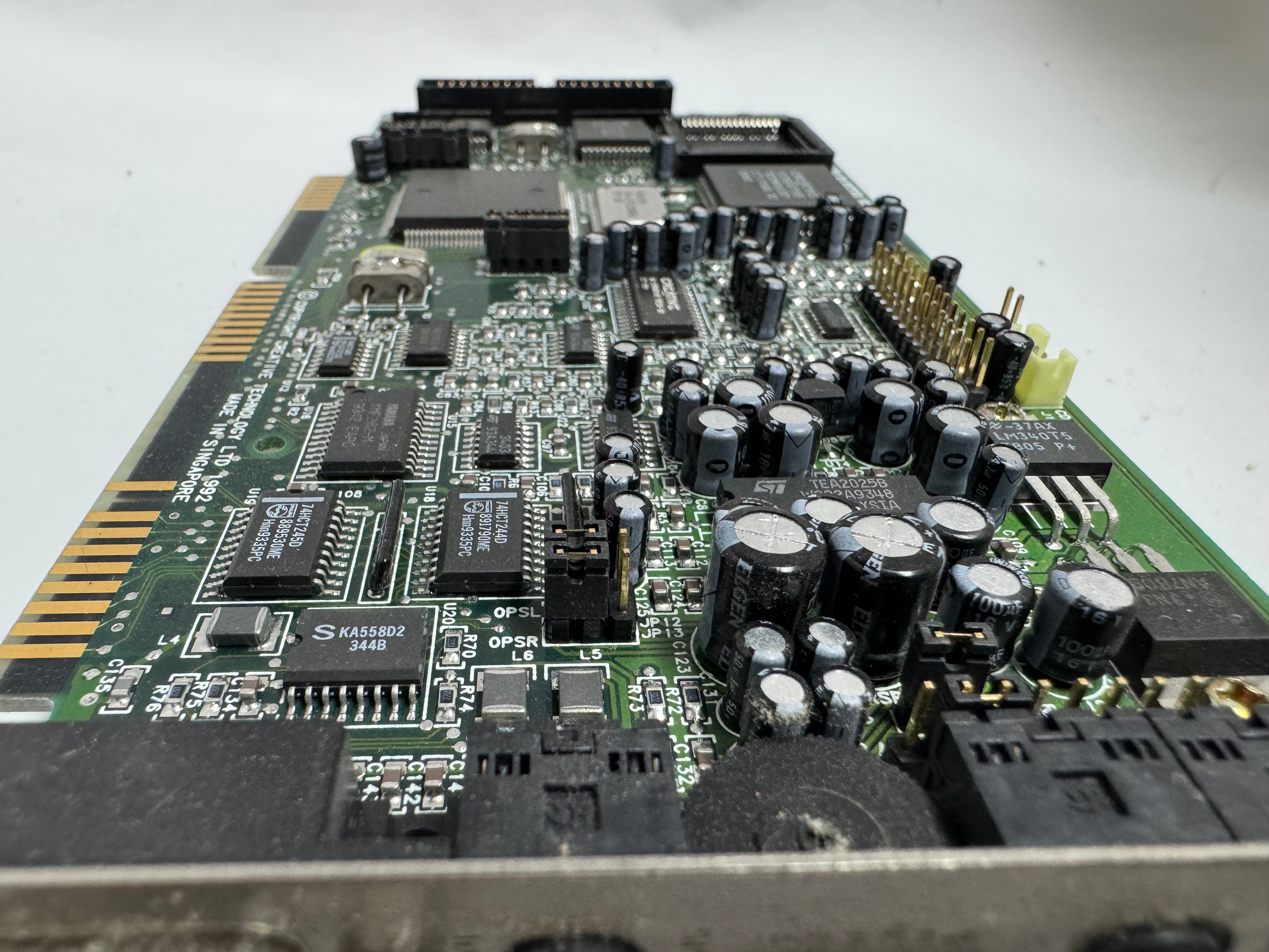
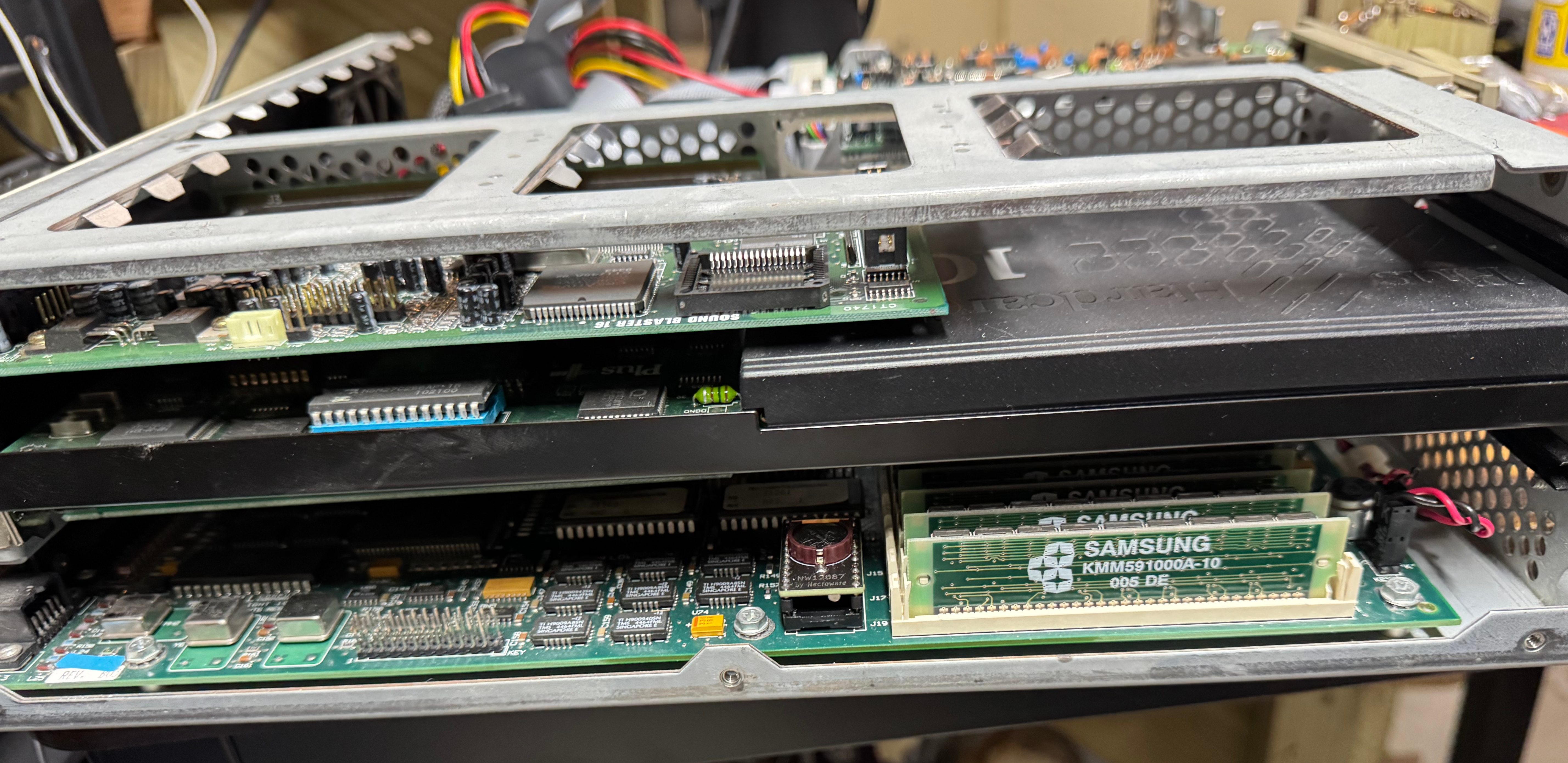
I got the Dell 316SX with a Hardcard II XL – 100MB ISA card and a Sound Blaster 16. I put some deoxit into the volume control knob of the Sound Blaster, it had the crackles when you moved it. That cleared it up.
I mentioned swapping the Hardcard for a SCSI controller. While I was in the system I also decided to get a 10MB Ethernet controller off ebay and put that into the system to have easier file transfers in the future.
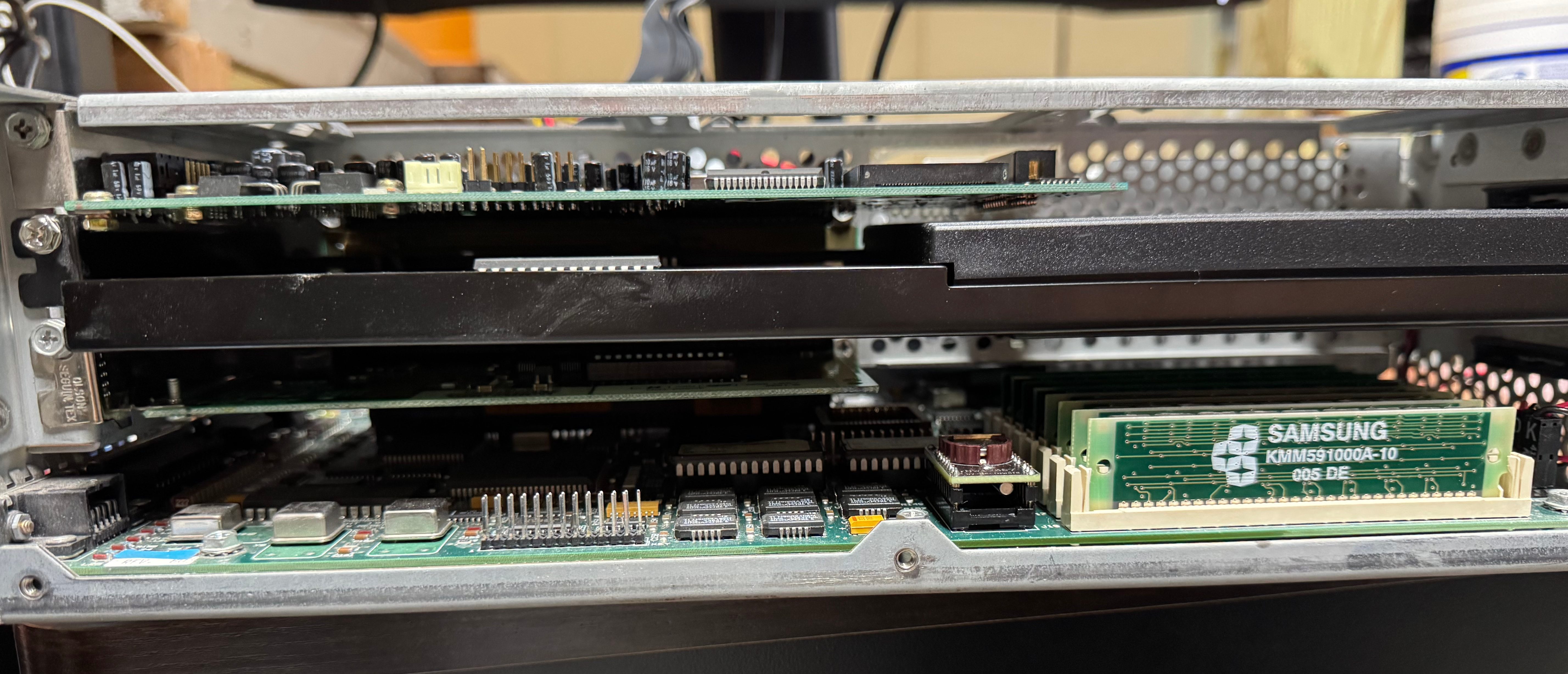
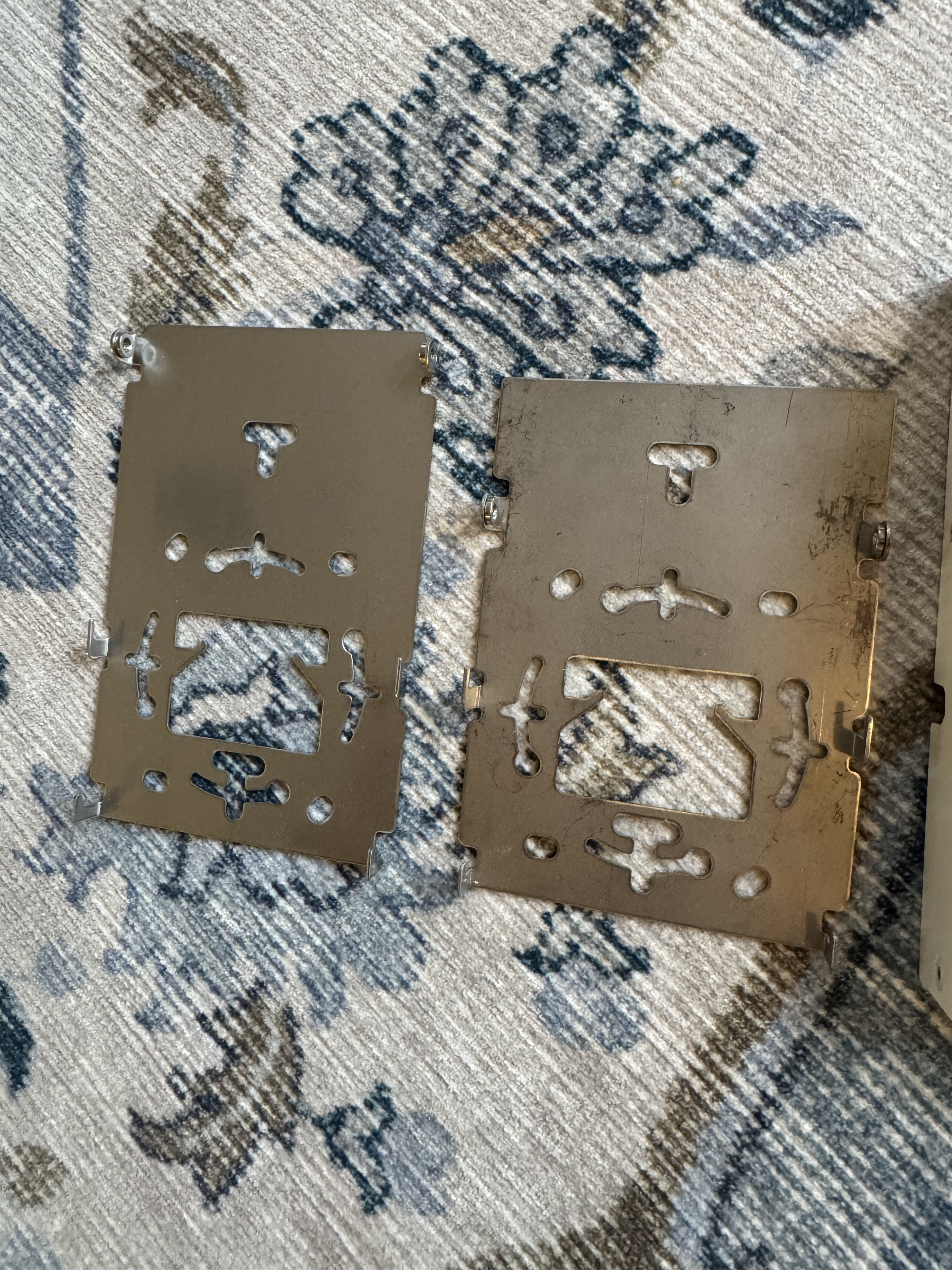
Sound Blaster 16Sound Blaster 16 BoardSound Blaster 16 BoardSound Blaster 16 BoardSound Blaster 16 BoardCard SandwichCard Sandwich while Hardcard was in thereCard Sandwich
Drives
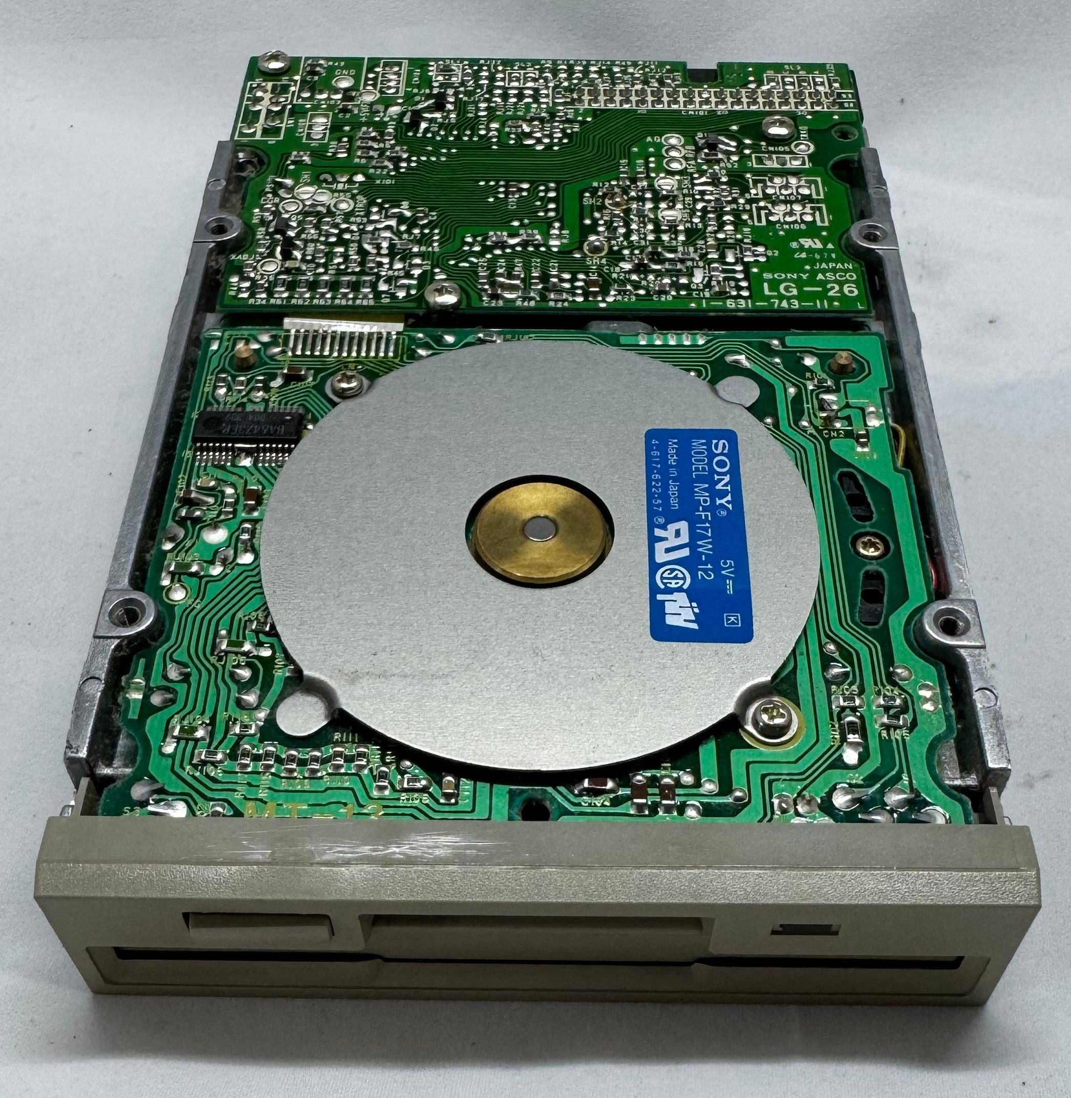
This Dell 316SX has a 5.25″ drive bay, and a 3.5″ bay. Both are working happily, but I did give them some lubricating grease on their rails after cleaning them up.
I put some time into cleaning the case. For being ~35 years old, it was looking in good condition.
Conclusion
In the end, I am very excited to have my childhood Dell 316SX back up and happily running. It took some work, with non-stop issues along the way; but in the end, its working with most of its original hardware. Below are some other photos I have taken. While I was working on the system I ordered 4 more 1MB SIMMs to bring the total memory to 8MB. I figured I would max it out while I had the system open. The only downside is the POST checks all the memory and this slows it down a bit.
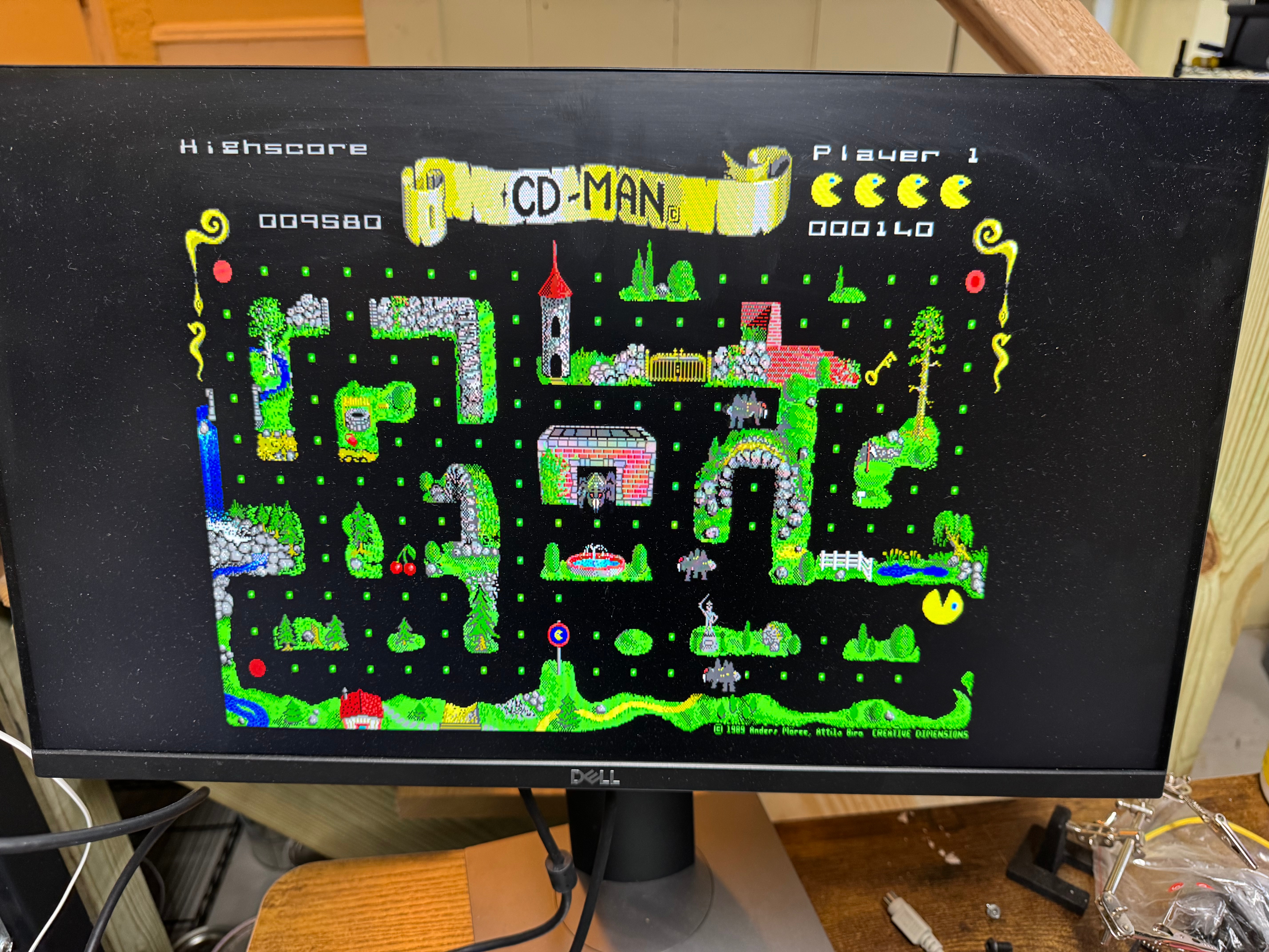
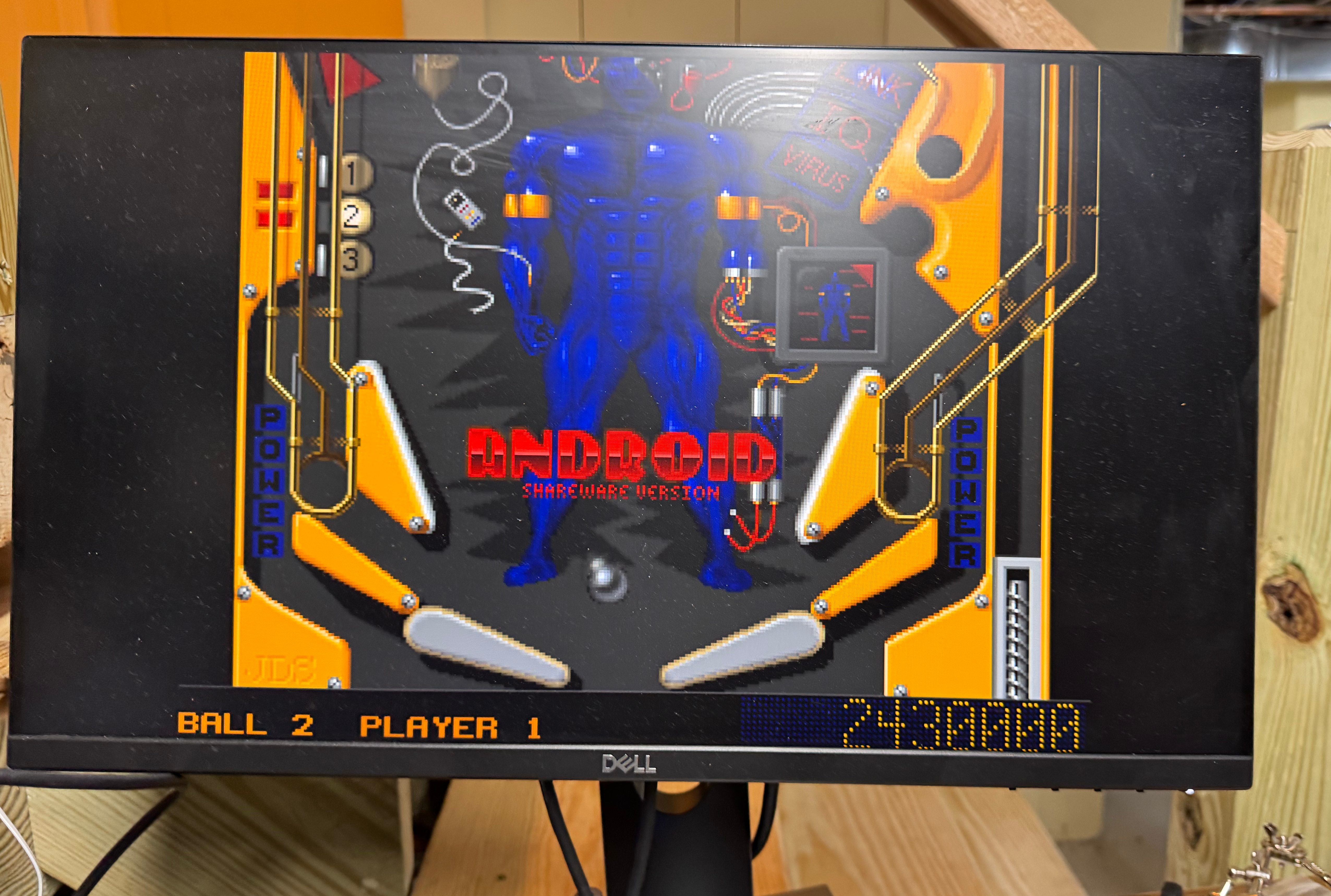
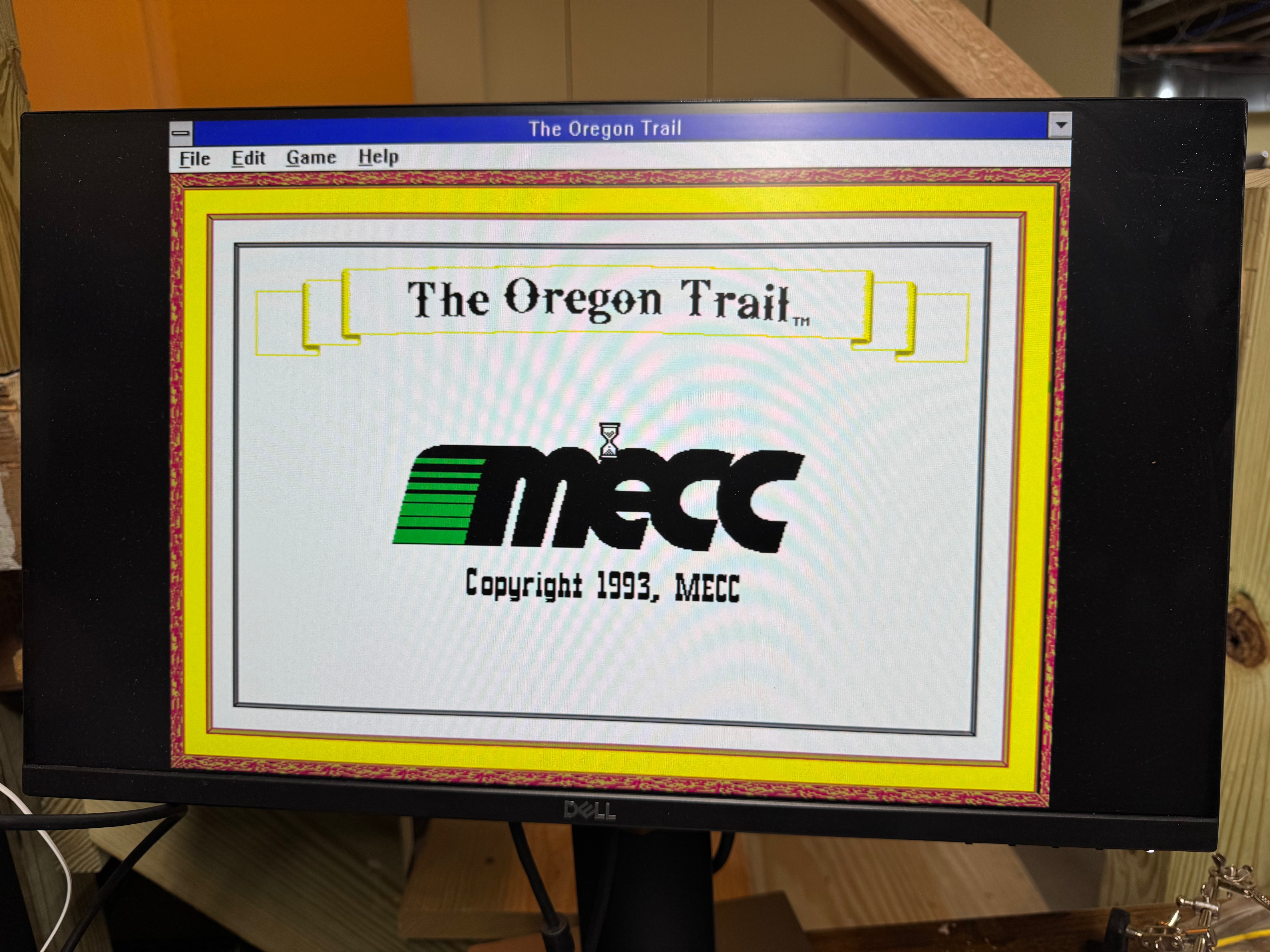
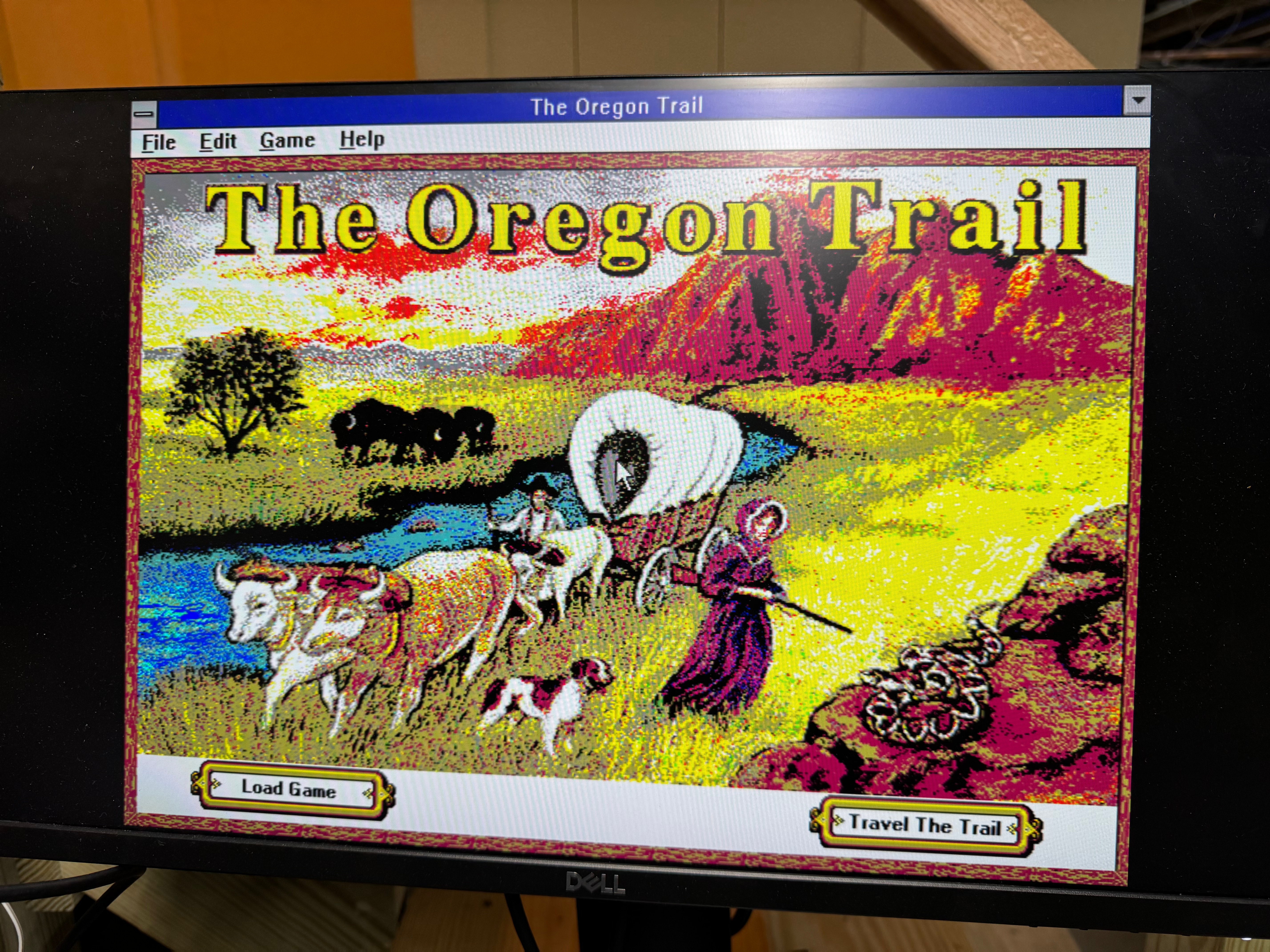
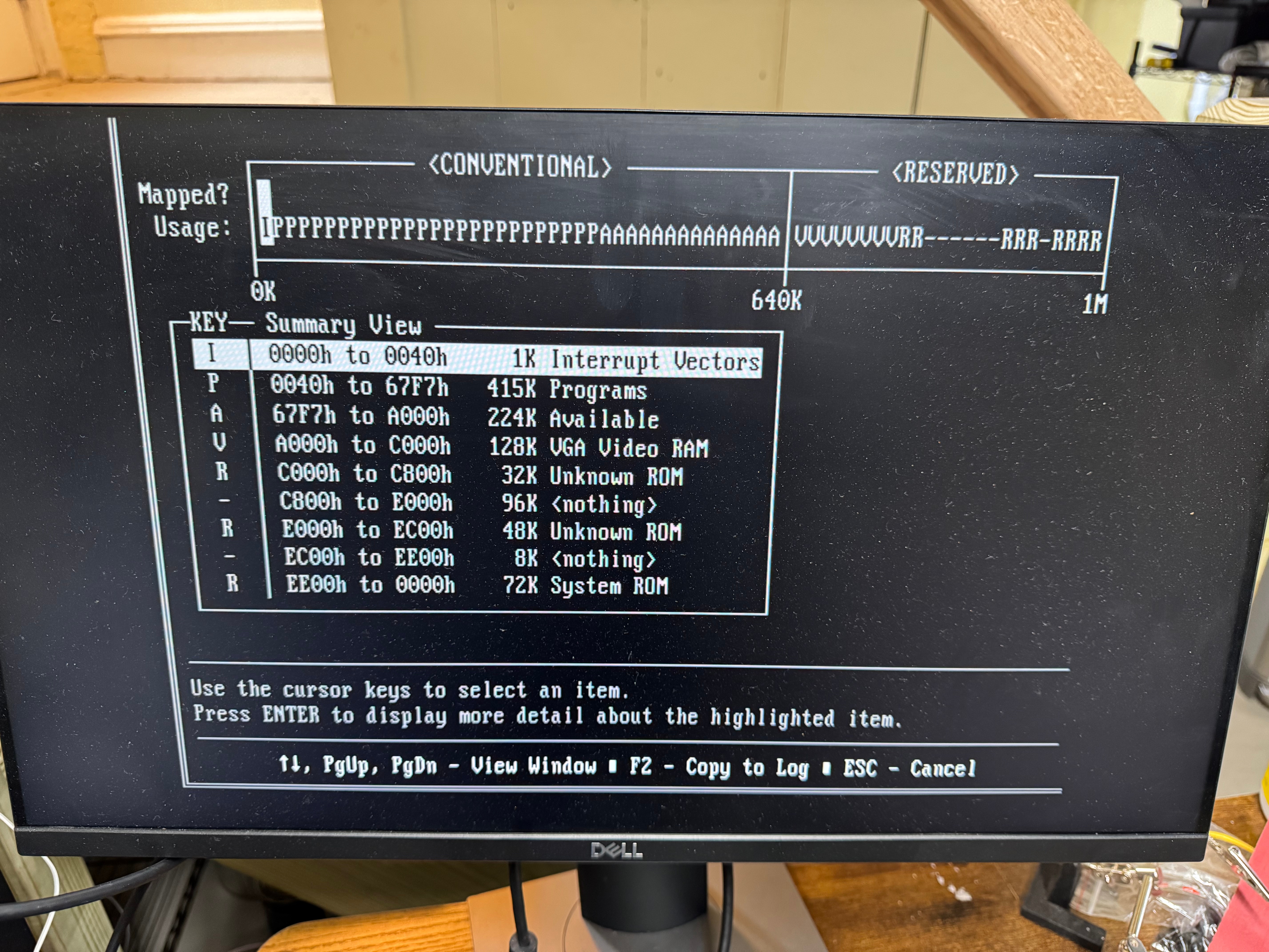
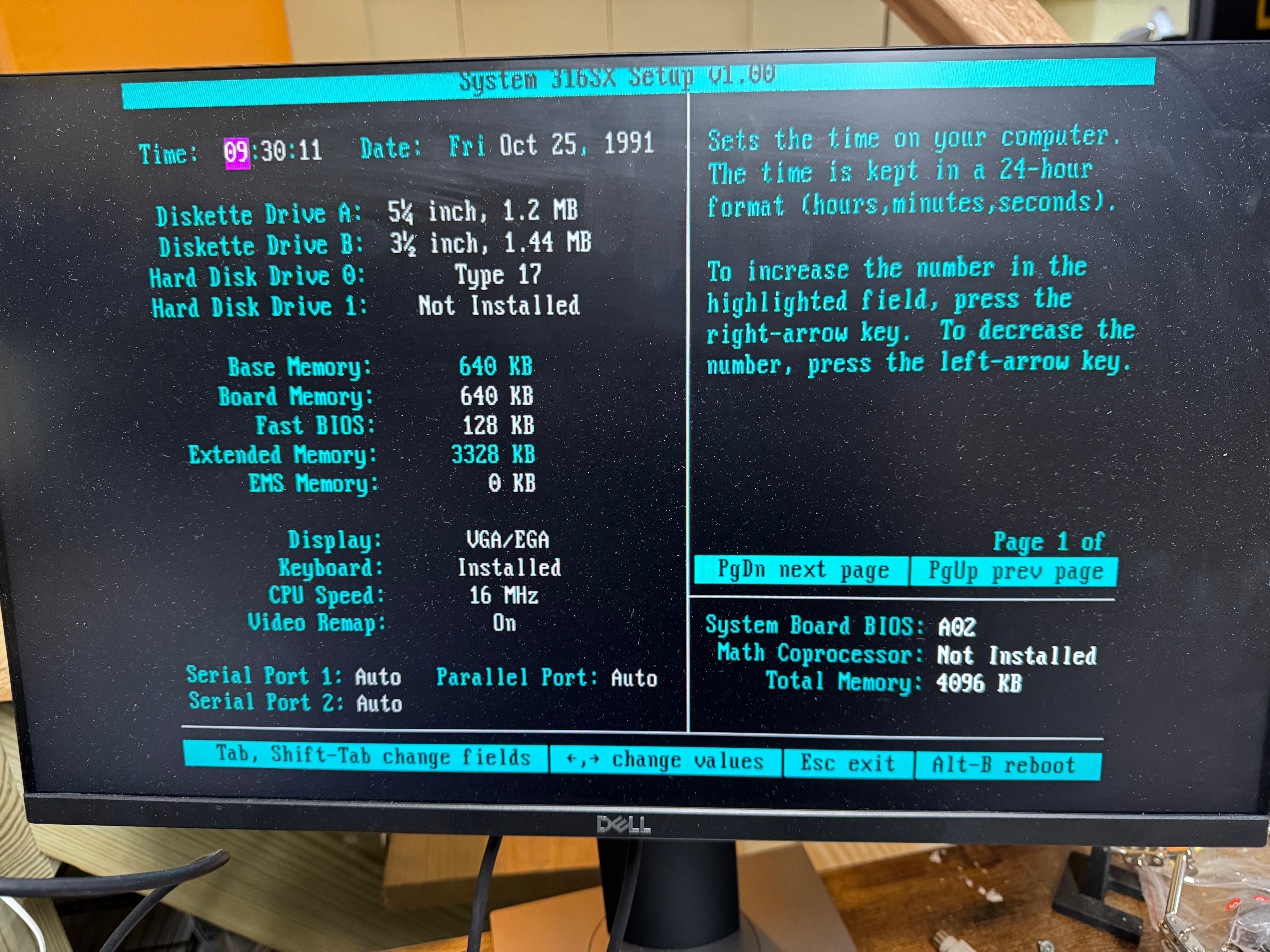
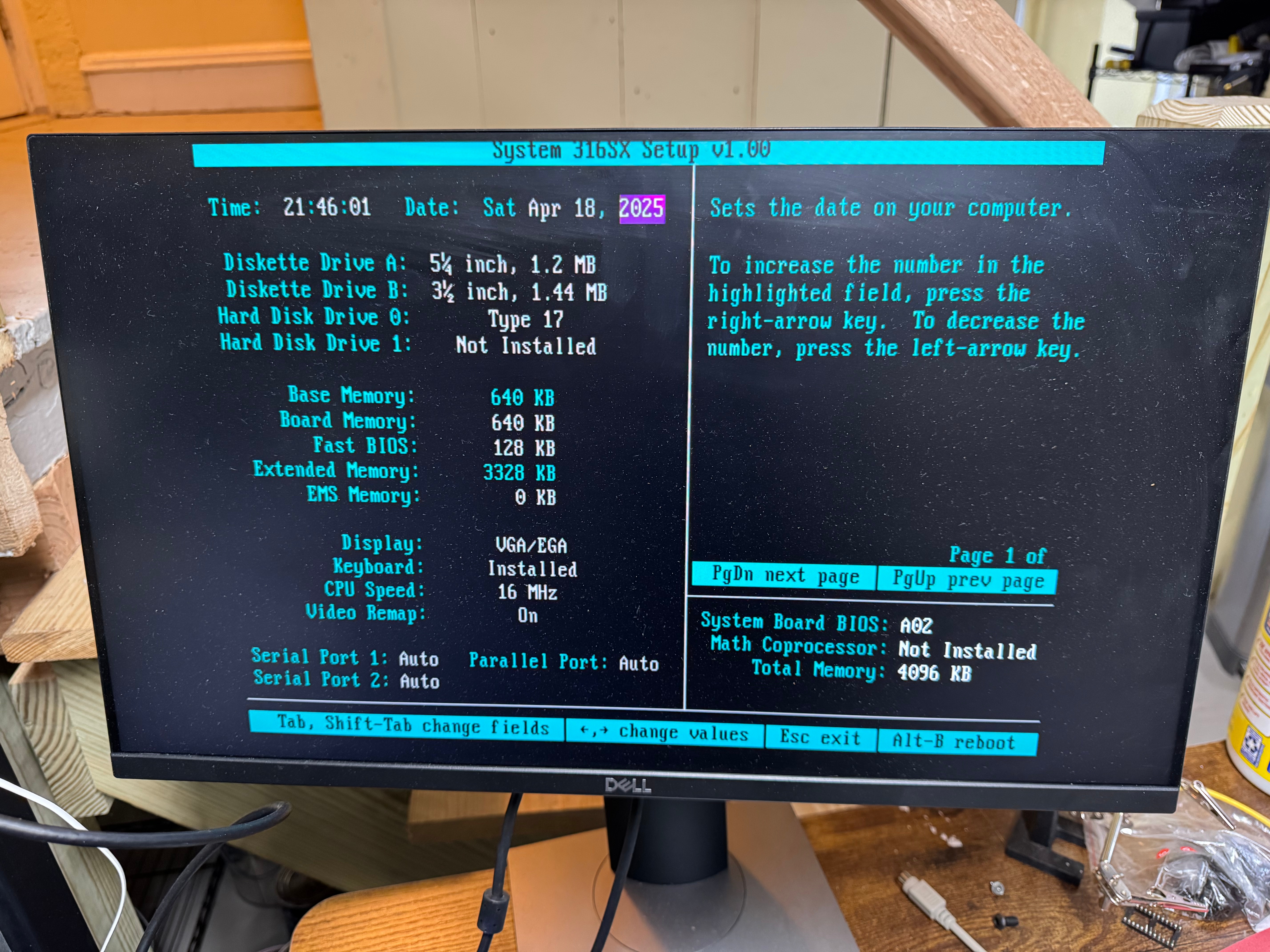
Windows 3.1 Booting!We are in!Prodigy!What was my login?CD-MANEpic PinballThe Oregon TrailThe Oregon TrailMemory MapThe BIOSThe BIOS accepts 2025!
I uploaded this playlist of a few videos I took working on the computer; they are in a playlist below.
I have a bad habit of buying networking gear when my work/life gets hectic. In a recent time of chaos I decided I should update a Ruckus H510 AP I have to a H550. I saw one on eBay, gave an offer and it was accepted! When the unit came, it still had the config of a news company. I had to factory reset it like mentioned in previous articles. The odd thing is it would not come up for me to access. I could see the “Configure.Me” Wifi network, but when I went to it nothing. I tried going to the web page and got nothing, I set the default IP and couldn’t contact it via wired. I then took out Wireshark and started looking for what happened when I joined its Wifi.
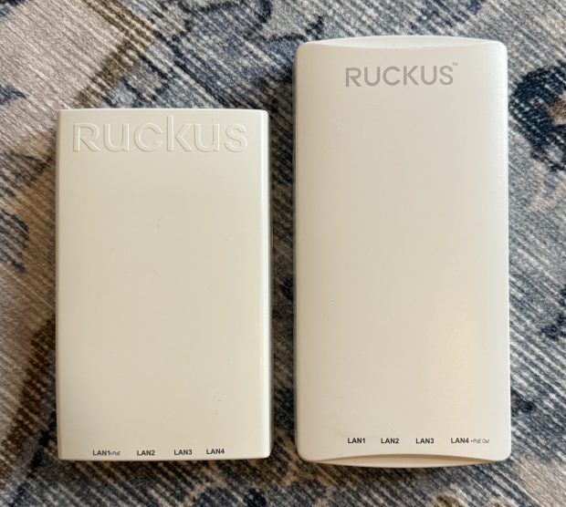
One other thing I didn’t realize… The H550 is taller than the H510… and I had a shelf right above the spot it was mounted. So I did the right thing, and mounted the new one upside down, so the taller part goes down and doesn’t hit the shelf.
While I was here getting more Wifi 6 goodness in my home (I have been running mostly Wifi 5 (802.11ac Wave 2) I thought I would look for deals. I saw someone selling a R550 for sale for parts. It said that when turned on it had a red light. I know that these access points can take a good 3-5 minutes to start, and while they do, they have a red light on… What are the chances that this access point just has a bad firmware image, or… nothing is wrong with it and this person just didn’t wait…
I offered $50 for the broken access point that usually goes for $250, and they accepted! Then I waited for the device to come, and later that week, I plugged it in, powered it up, and… it booted fine! I flashed it over to Unleashed and suddenly I had another great Wifi 6 access point.
I have mostly moved all my access points to Wifi 6 at this point which means I can go above firmware 200.15 (the last for the Wifi 5 systems), but I still haven’t since its still recommended to stay there by some places. And I am pondering setting up the old H510 as a small access point and ethernet port at my workbench.
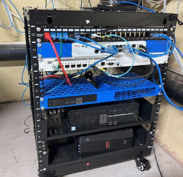
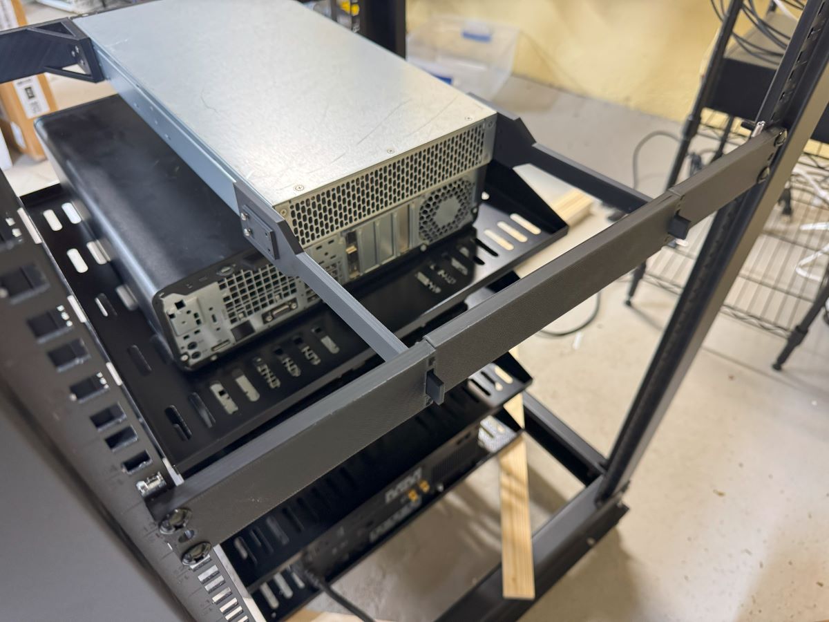
I recently got some more space to do my homelab endeavors. I am enjoying setting up a proper work bench for soldering, and I got a few racks to put different projects in! I am trying to stay focused on projects and get them done, but there are so many to do!
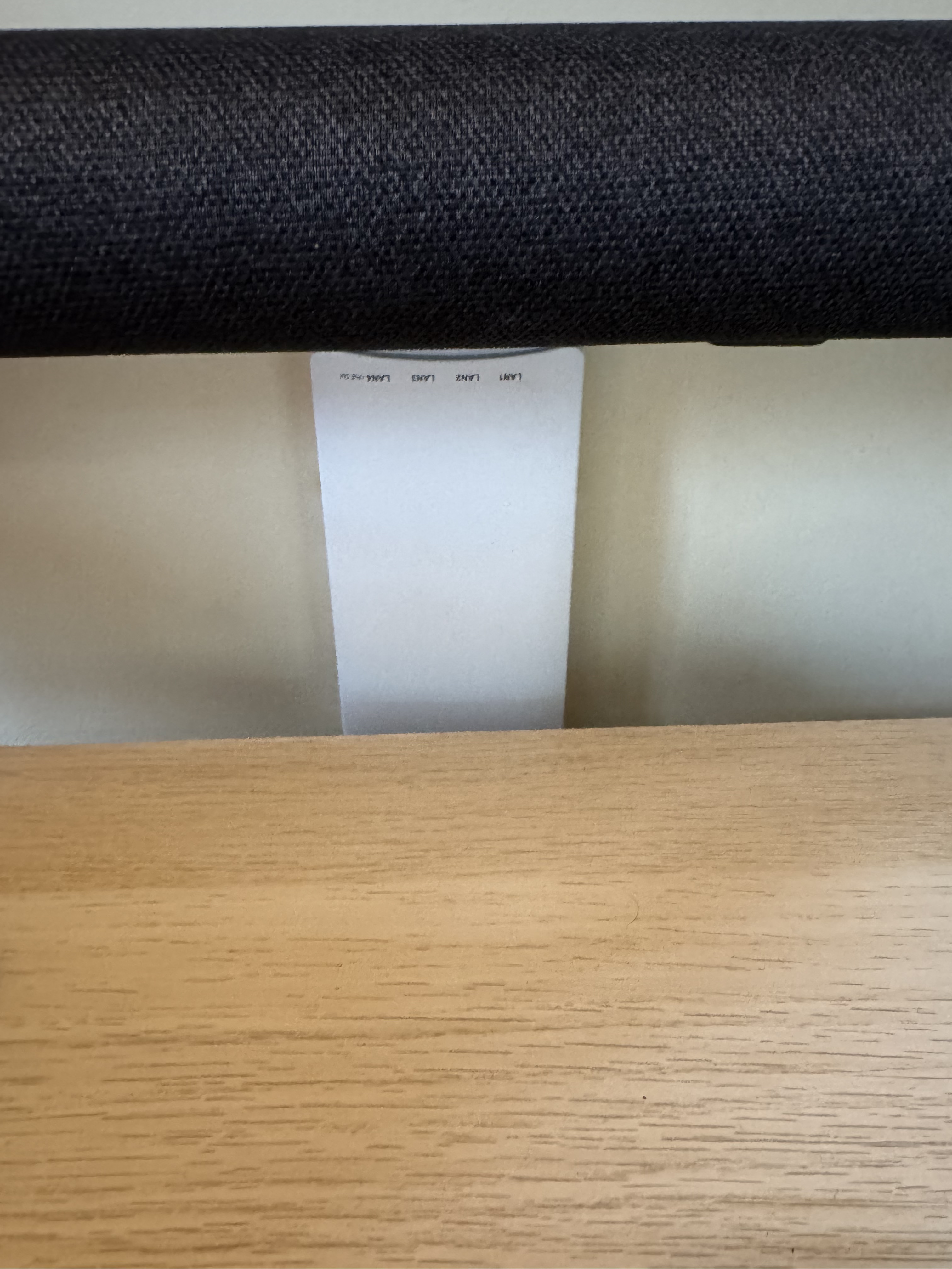
I had our home internet coming in on a little cart and decided it was time to get a small 12U rack, and properly set everything up. The issue is over the years, I acquired switches and gear and not rack ears for them since I wouldn’t need them at the time. I spent the last few weeks working on a few different rack ears for different pieces of gear I have. I also printed this (Dell Micro 1U Rack Mount Remixed by noam_f – MakerWorld) model which allows you to mount Dell Micro computers in 1U. This is nice since my primary domain controller is running on one of those. Someone else made a model of a shelf to hold the power supply (Power Adapter Mount for Dell Micro 1U Rack Mount by Jfrorie | Download free STL model | Printables.com)!
I used metal 2U shelves for the systems I currently have running ESXi. That may be going away soon with all the changes to VMUG licenses. Ill post later more about the state of the racks and network as it progresses.
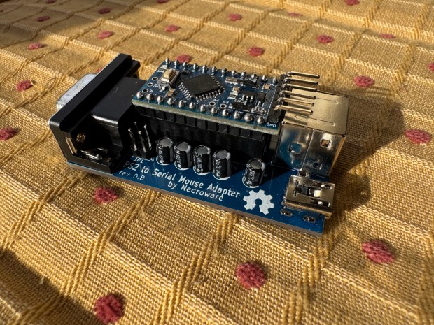
As part of my LAN Before Time rack project, I’m setting up classic PCs with a VGA and PS/2 KVM to manage them. However, one of my systems—a 486—lacks a PS/2 port for the mouse. A simple PS/2-to-serial adapter wasn’t enough; it required a proper signal conversion to work.
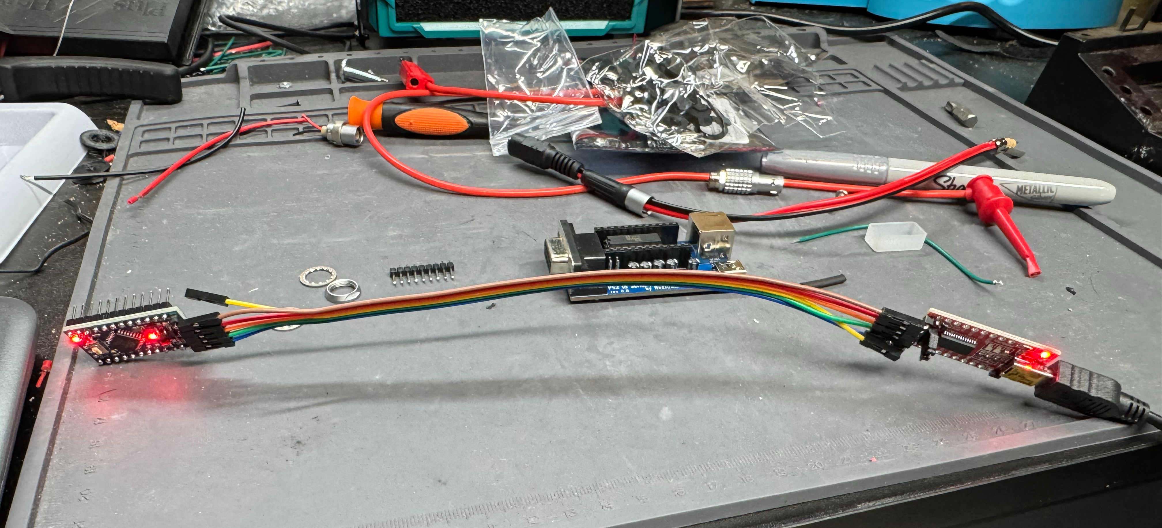
After some searching, I found this adapter kit on eBay: PS/2 to Serial Mouse Adapter. It’s based on an open-source project: necroware/ps2-serial-mouse-adapter. The kit didn’t include instructions, and the project assumes you already know how to assemble it; I decided to document my build process step by step.
A Quick Note on KVM Compatibility
This adapter worked flawlessly when I plugged a PS/2 HP Laser Mouse directly into the 486. However, when connected through my KVM, it worked for a few seconds before stopping. After some digging, I found a pull request from last year that mentioned a KVM fix. Flashing that updated firmware completely resolved my issue! Unfortunately, the main repository hasn’t been updated in two years, so hopefully, it gets some attention.
What’s Next?
Below, I’ll walk through assembling the adapter. After that, I’ll cover how to flash the updated firmware using a USB-to-TTL converter. These converters are cheap and easy to find—here’s the one I used: USB to TTL Adapter. Finally, I will show a case I designed and 3D printed for the device.
Steps
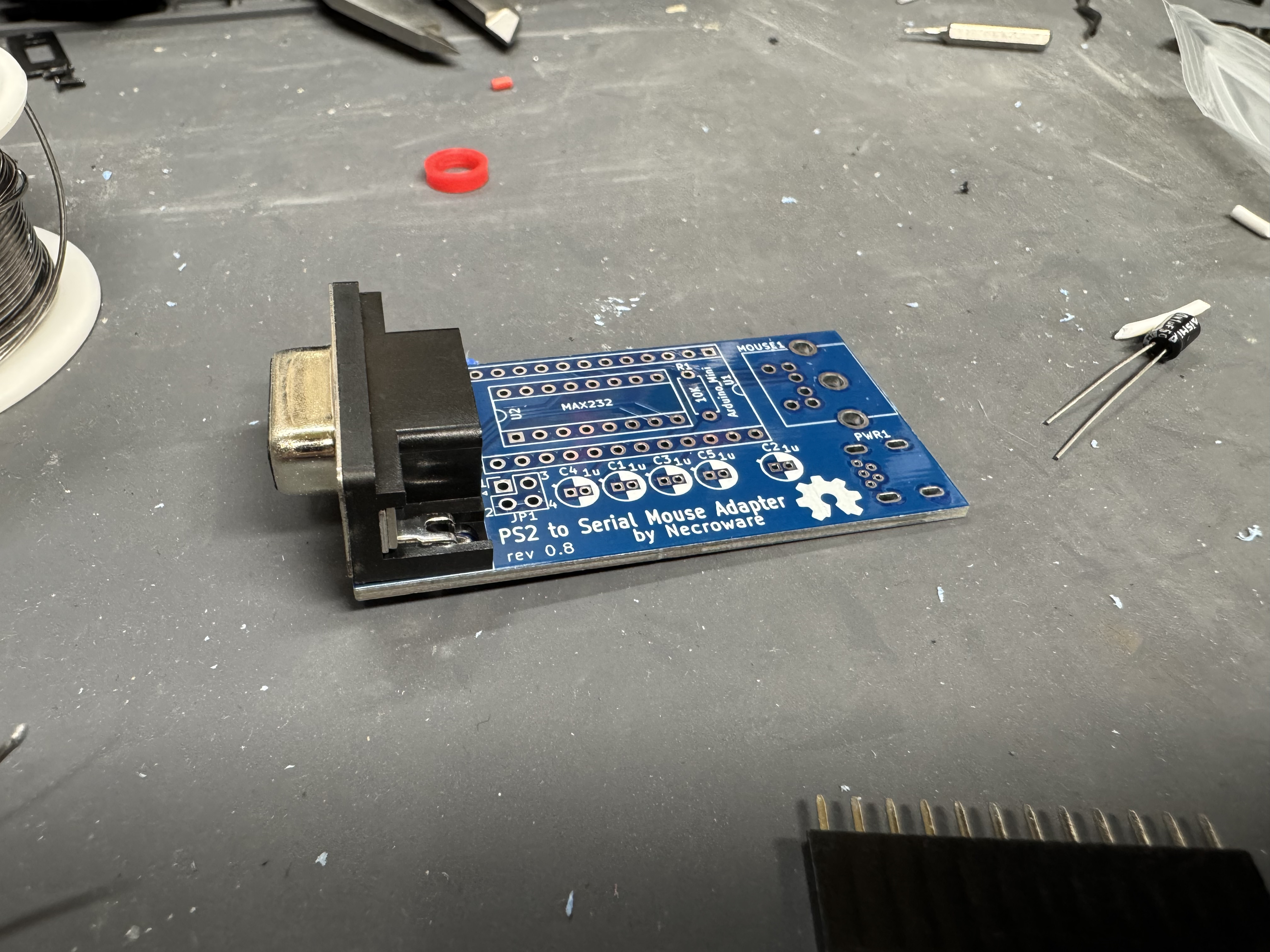
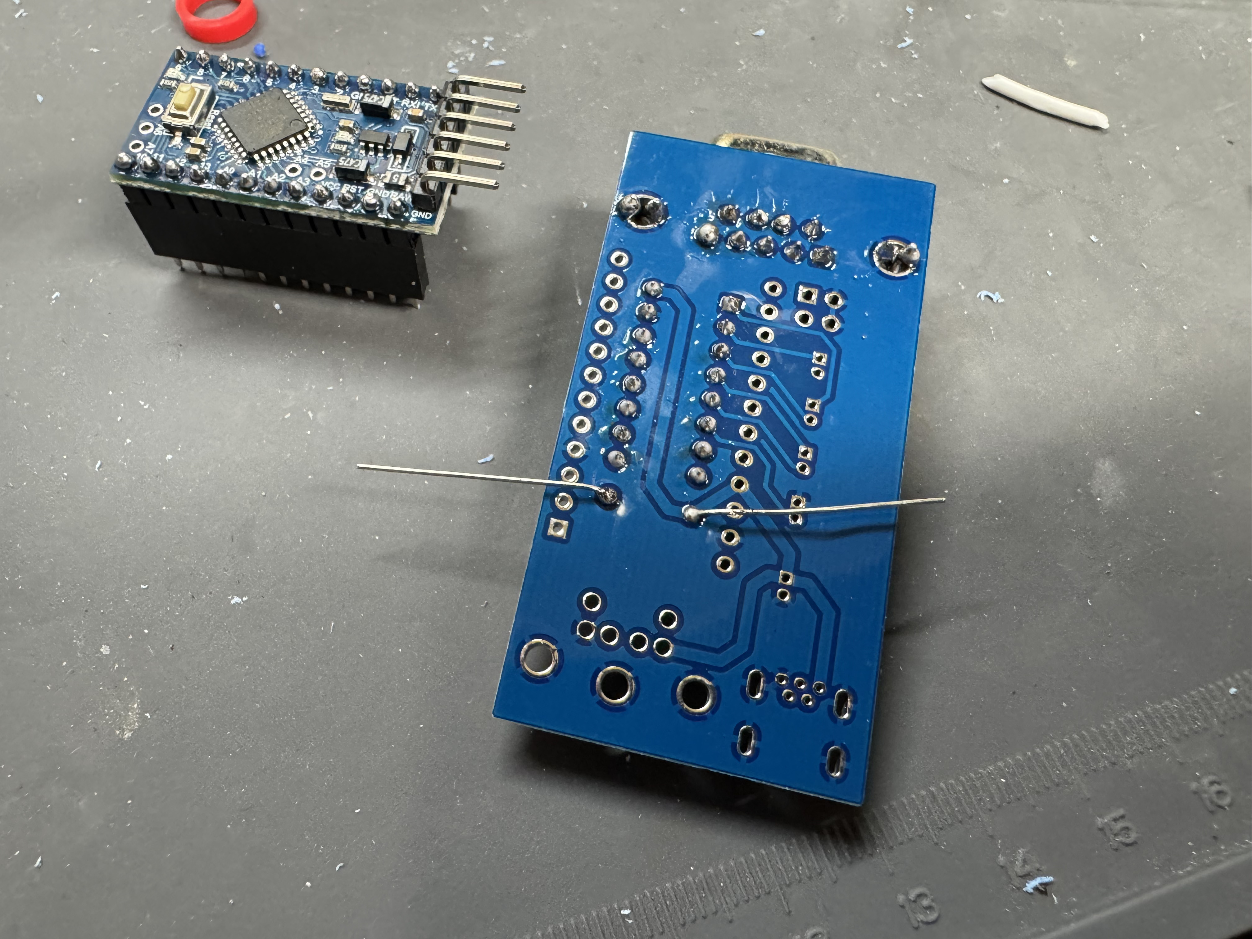
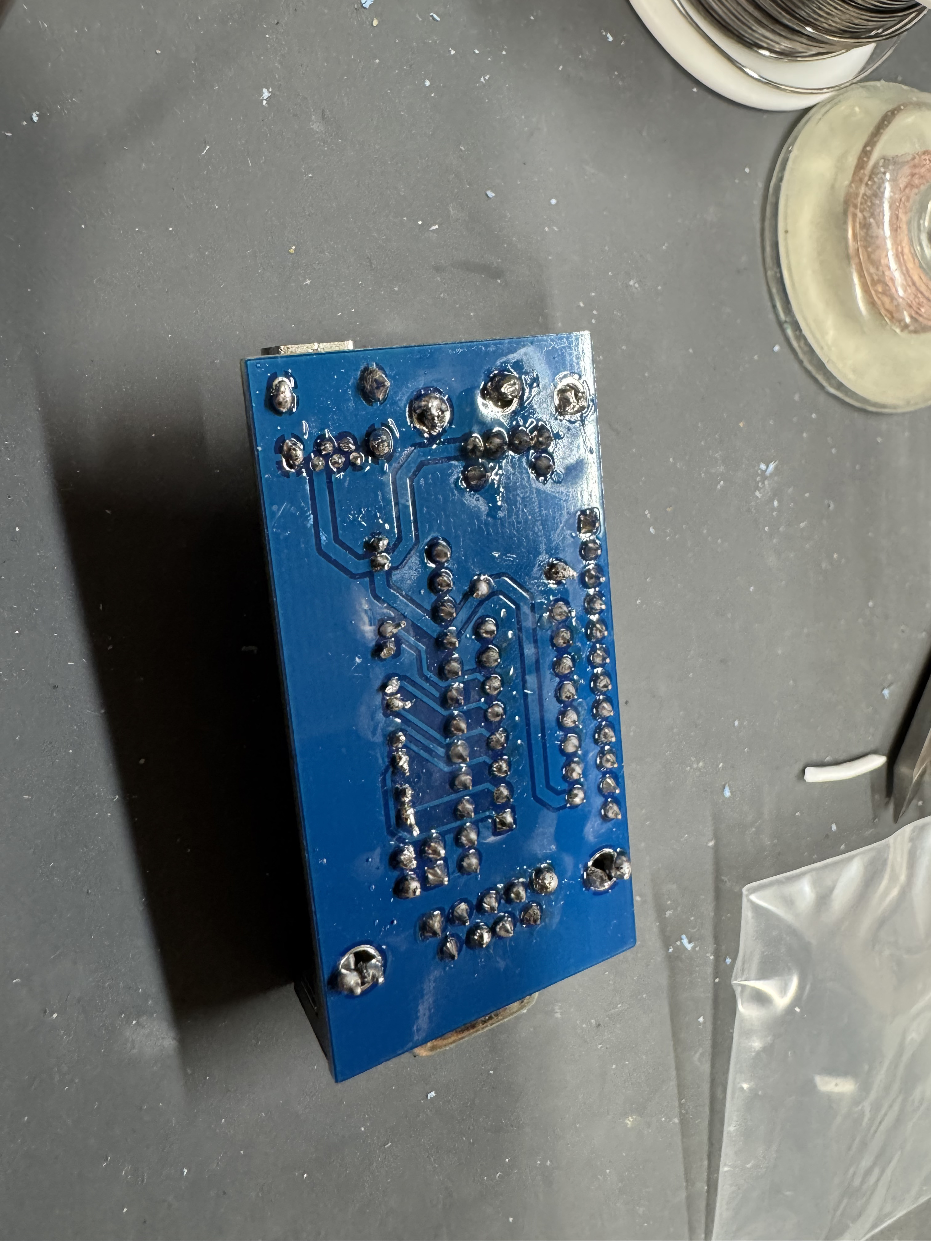
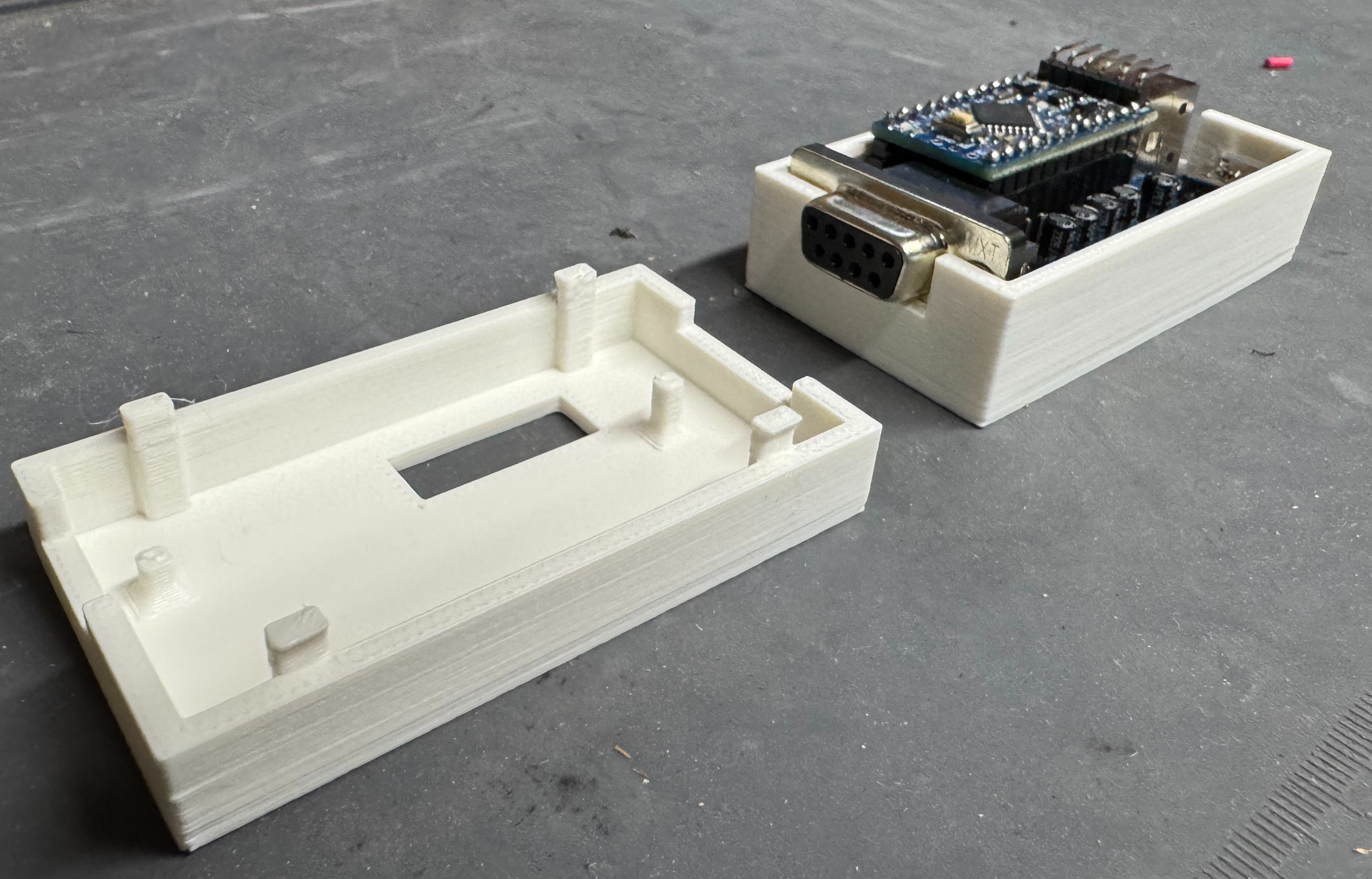
Put the serial connector through the top side of the board and solder it in place on the bottom, starting with the mounting legs and using plenty of solder. These take a lot of the strain of the connections. Then carefully do each of the data pins, making sure not to bridge any.
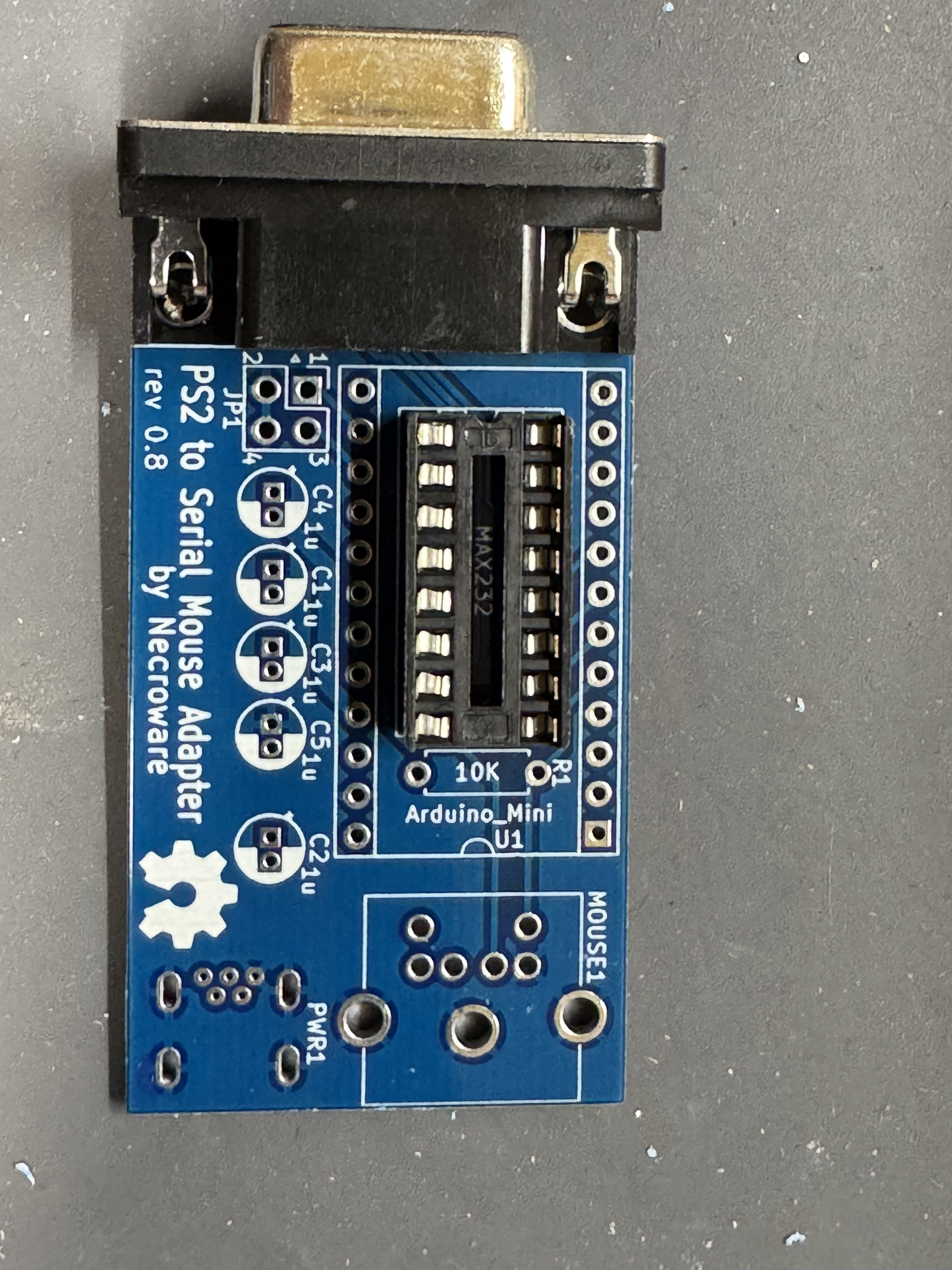
Insert the lower chip socket, and solder in place on the underside.
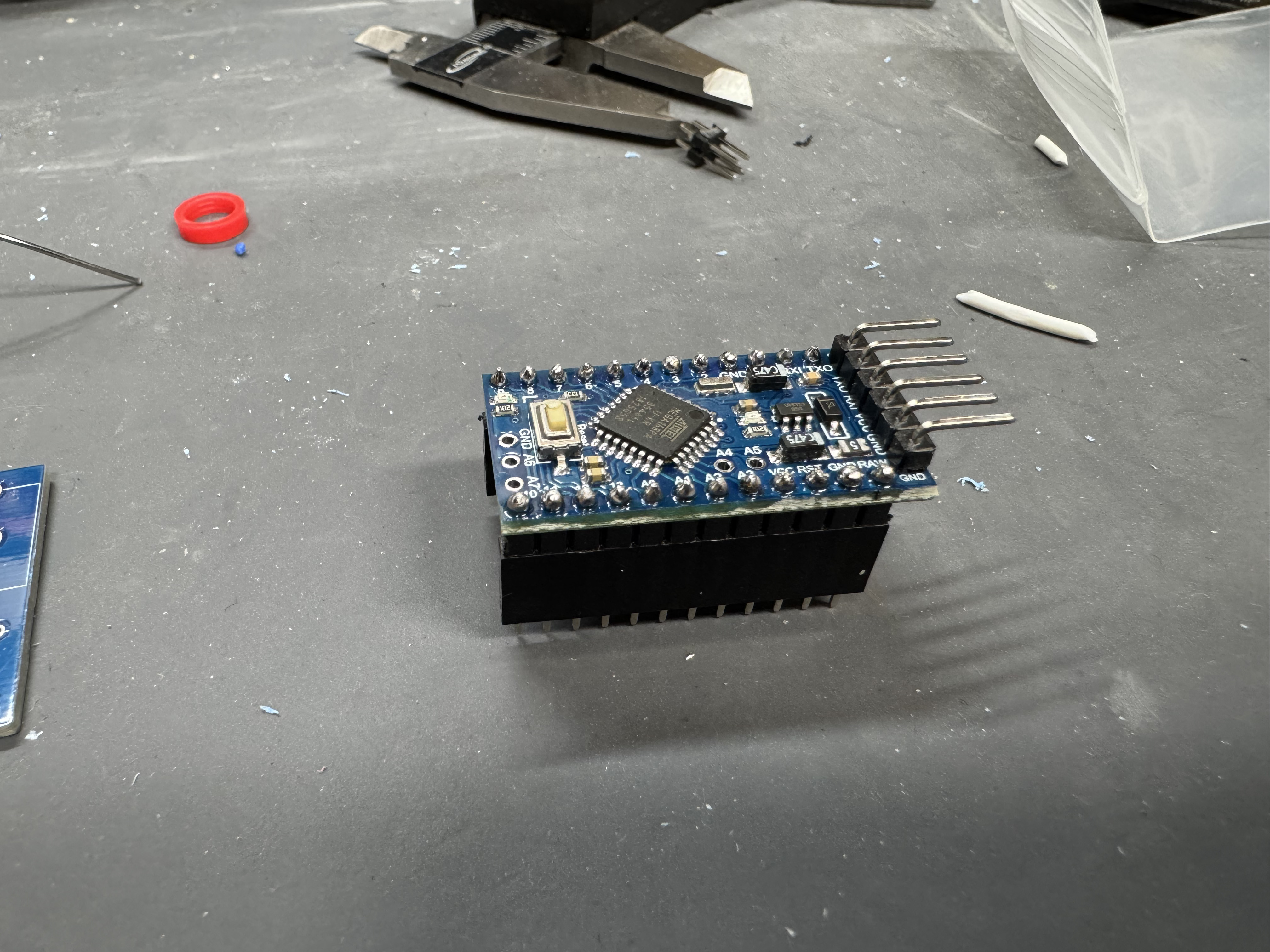
The Arduino Pro has 3 different parts we need to solder. The first is the head with the 90 degree pins at the end. This will allow us later to flash the controller if we want to move to other firmware. Put those through the top (the side with the chip) and then solder them in the underside.
Next, put the Arduino header pins in the bottom. I put them into the header connector to hold them in place. Do not put too much heat on each pin with the plastic part below. (Not my best soldering job)
Solder in the 10k resister, here I am soldering it on the bottom while it went in through the top. After it is in, cut of the excess legs.
Solder in the PS/2 port, use a good amount of solder on the mounting points so it doesn’t move when inserted, then solder the data pins.
Solder in the micro-usb port, careful of the tiny pins.
Add the jumper pins, solder them in.
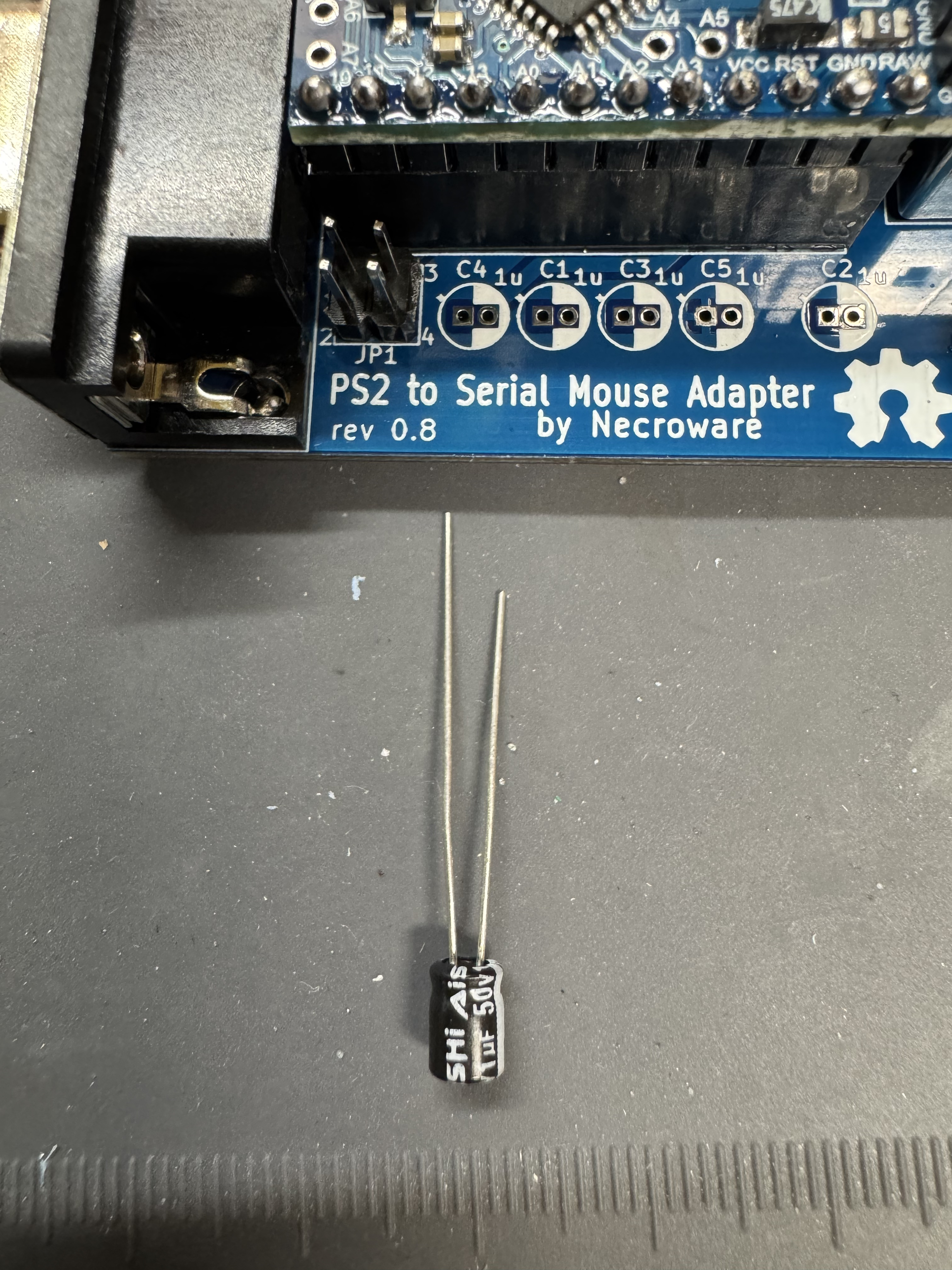
Now time for the capacitors, these are polarized, note the right side of the silk screen is white that should line up with the white side of the cap. (the shorter leg side)
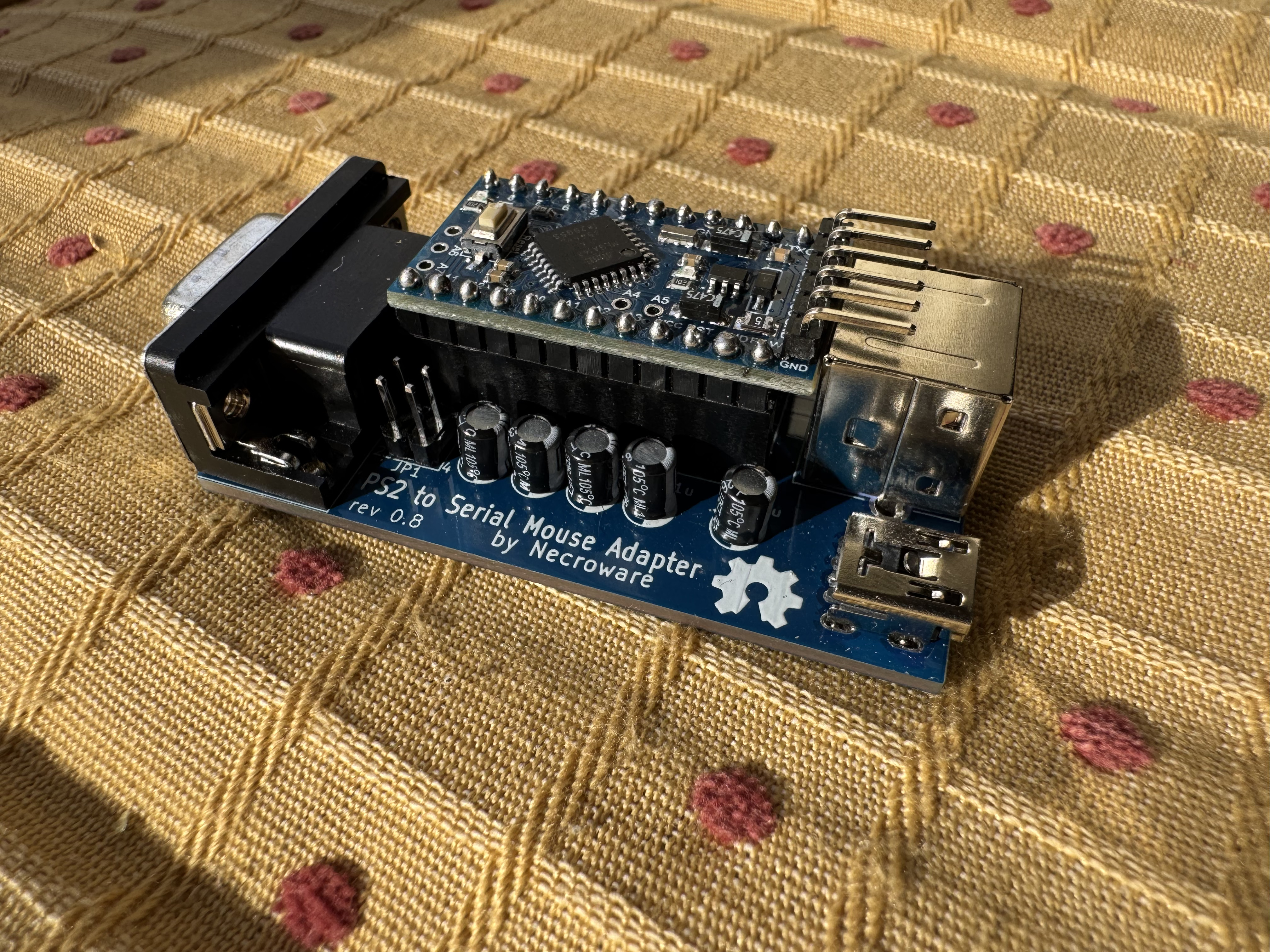
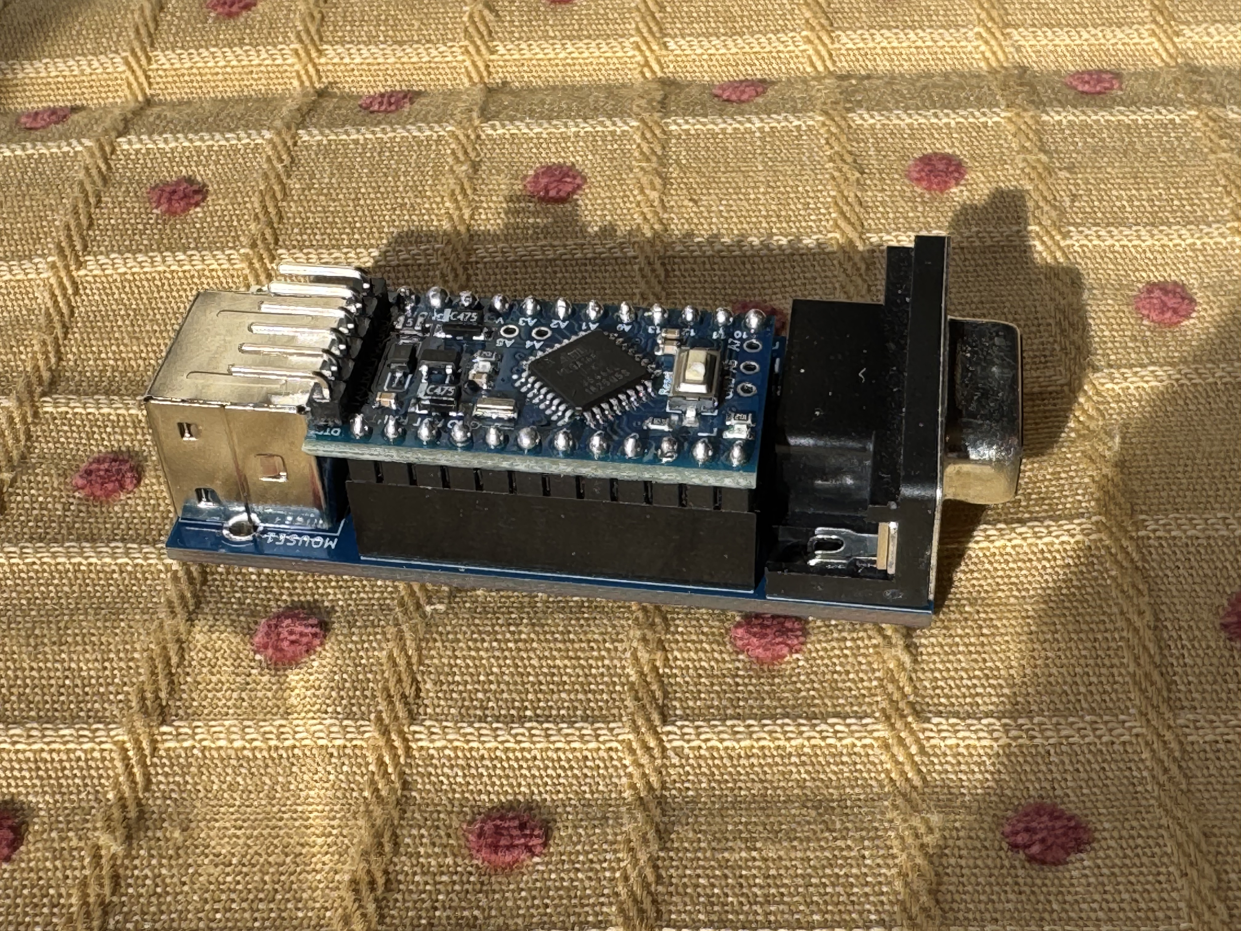
Finish up by soldering all the pin headers for the controller to sit on the board.
The board should now be complete! If you bought it from the seller I did, (who has been great, and I have bought other items from) then you have the main repos firmware on it. I won’t go too far in depth for this, but if you clone the fork down you can then use Platform.IO to flash the firmware. There are guides out there to do this on. Platform.IO is great when doing Arduino projects.
If you go the same kit I did, then it comes with a “pro16MHzatmega168” not the “pro16MHzatmega328” used in the Pull Request. Change the two lines where the 328 is mentioned to the 168-model string. If you do not, you will get a “timeout connecting to Arduino” when attempting to flash.
As mentioned, you need a TTL converter, then to flash the chip. The TTL converter (which I hadn’t used before) pins actually line up with the pins on the Arduino Pro. You need to hold it there for a total of 30 seconds while it flashes. You can just stick the header pins of the Arduino through the holes of the converter, then hit send via Platform.IO.
Flashing the new firmware on my messy desk, I did not need long cables like this…
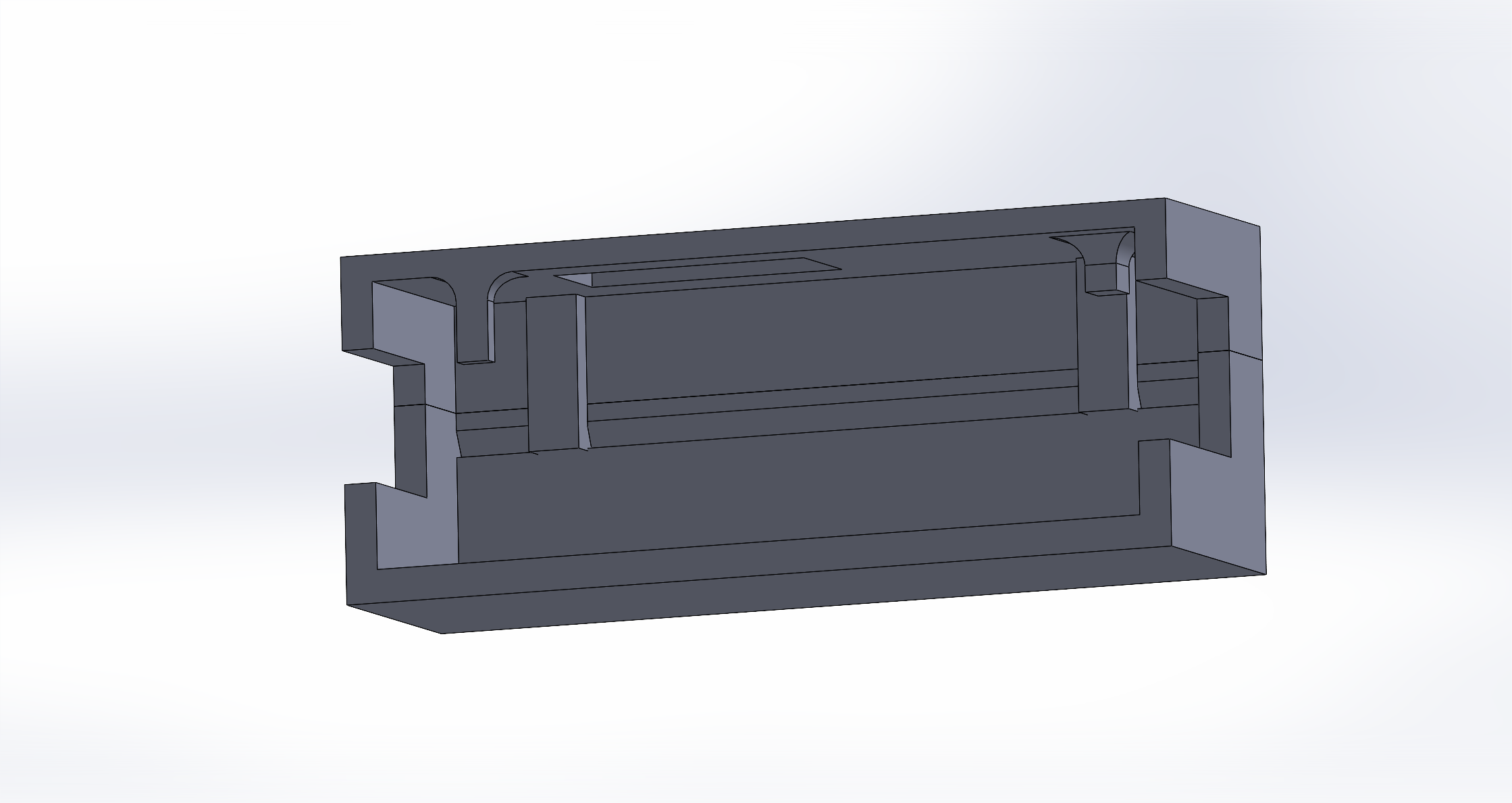
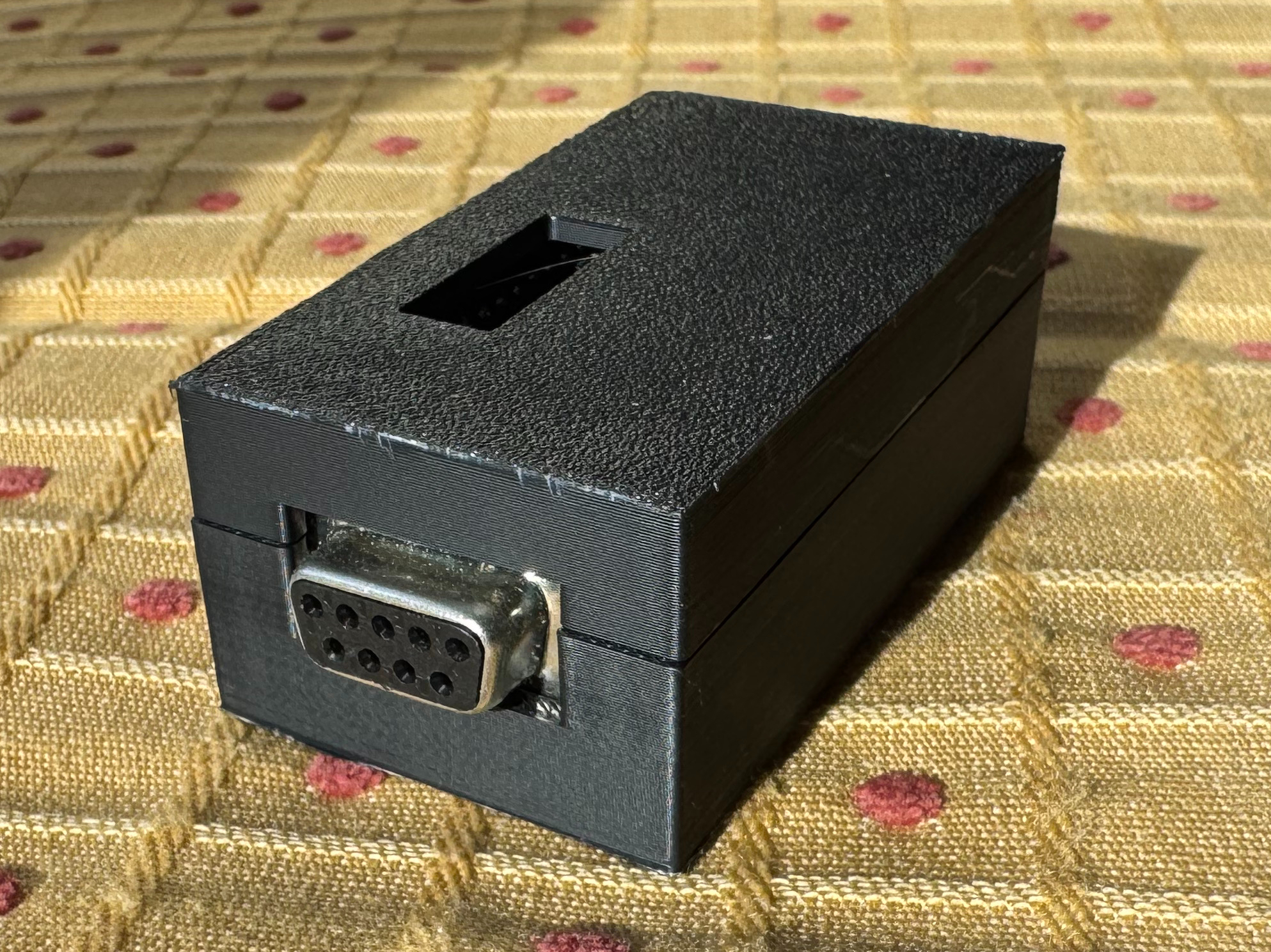
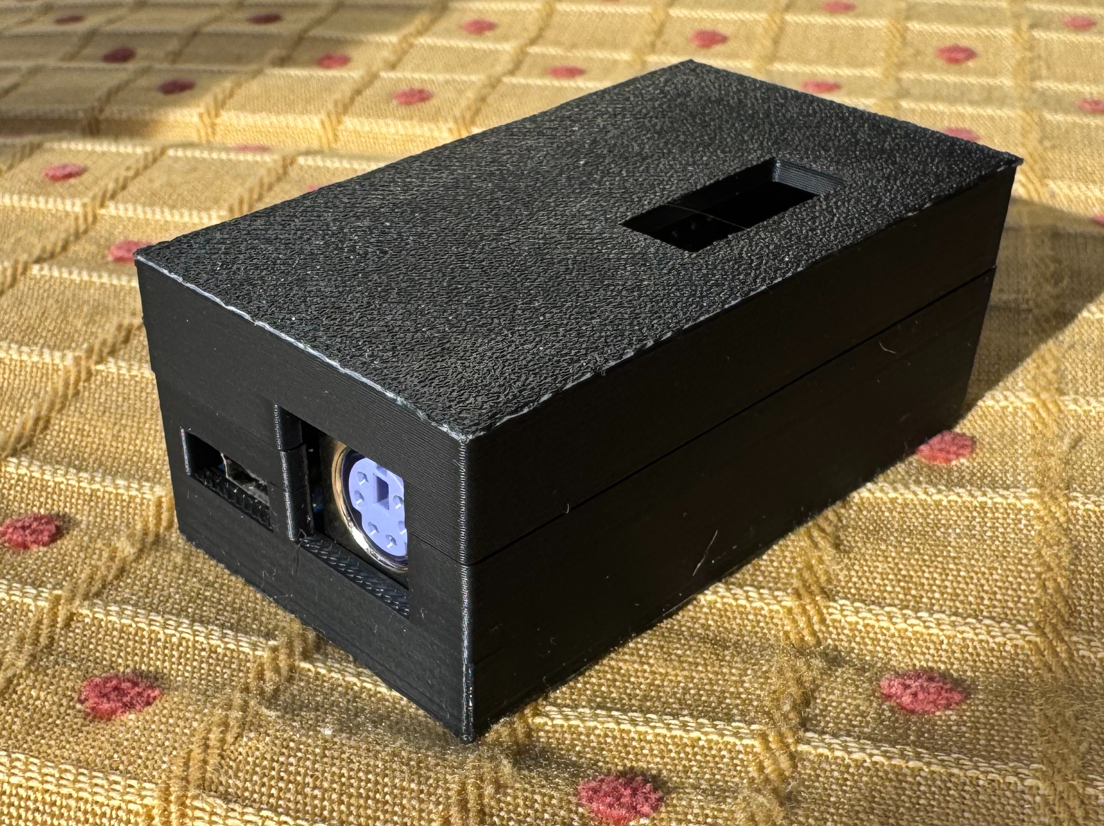
3D Printed Case
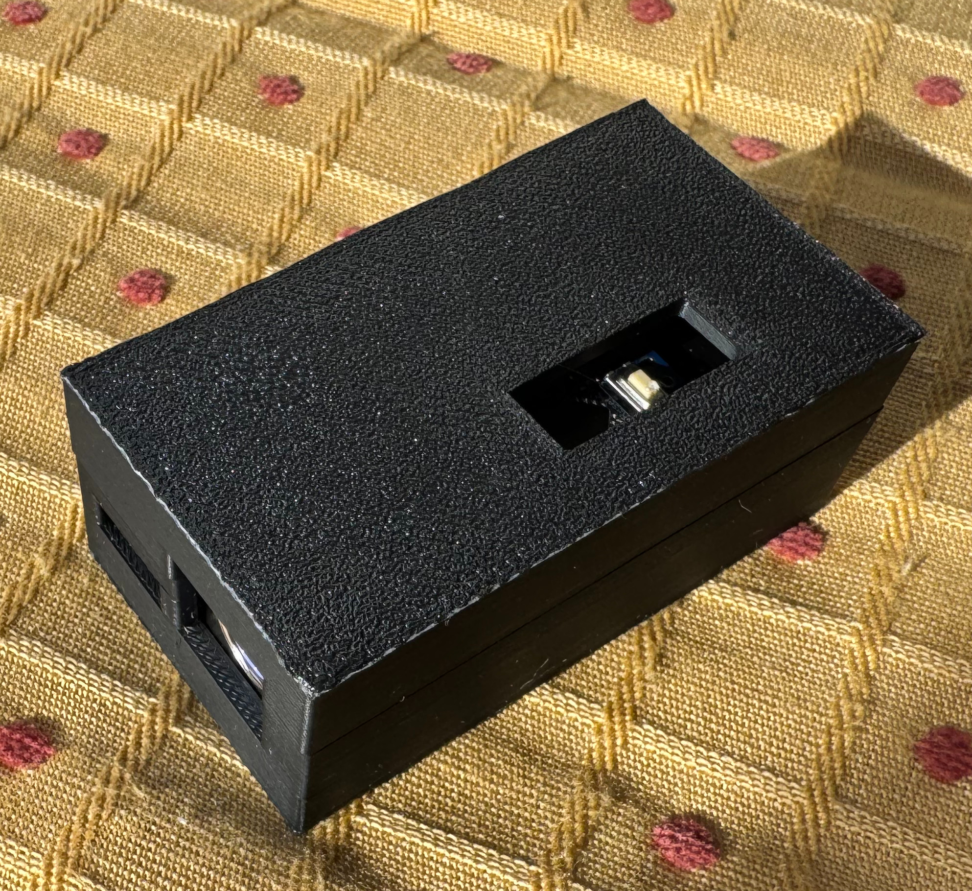
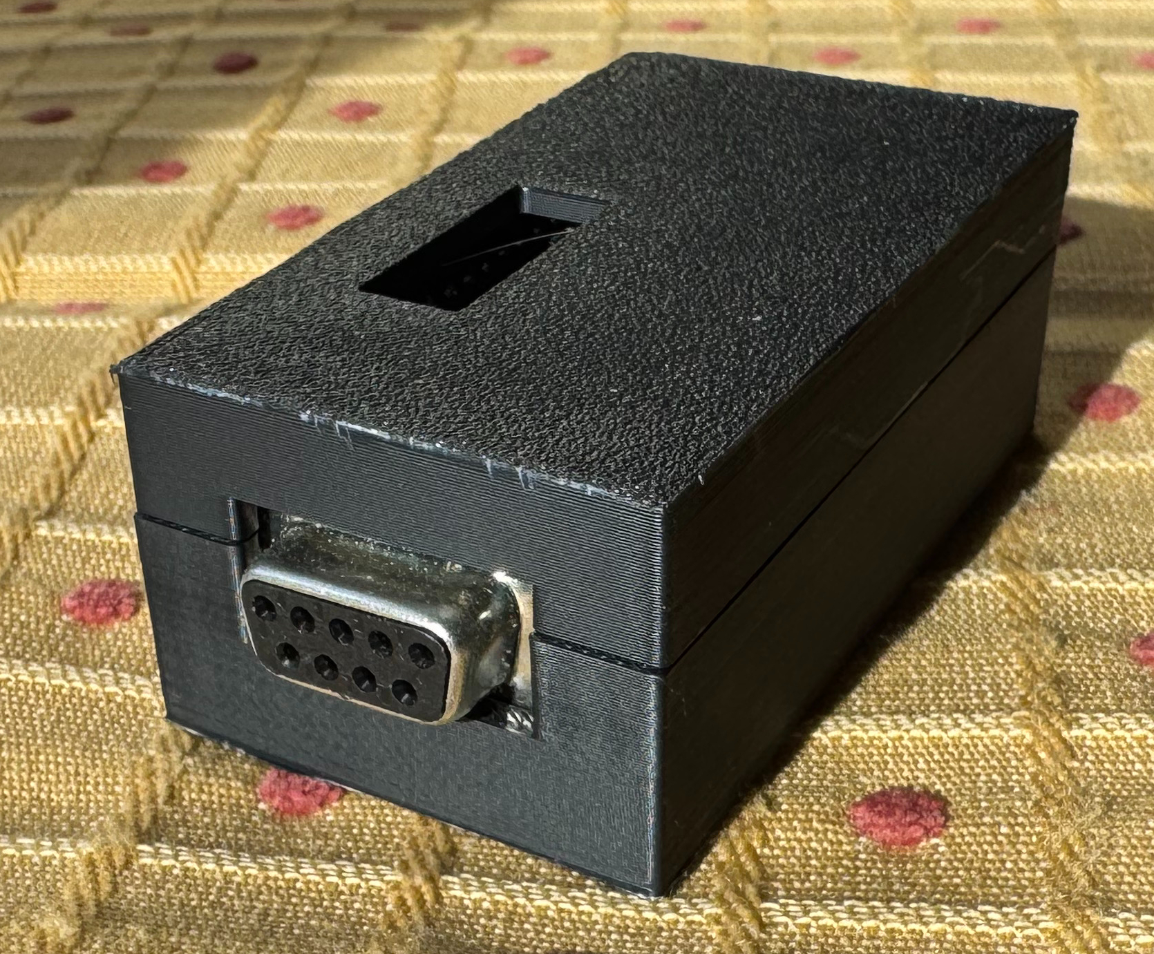
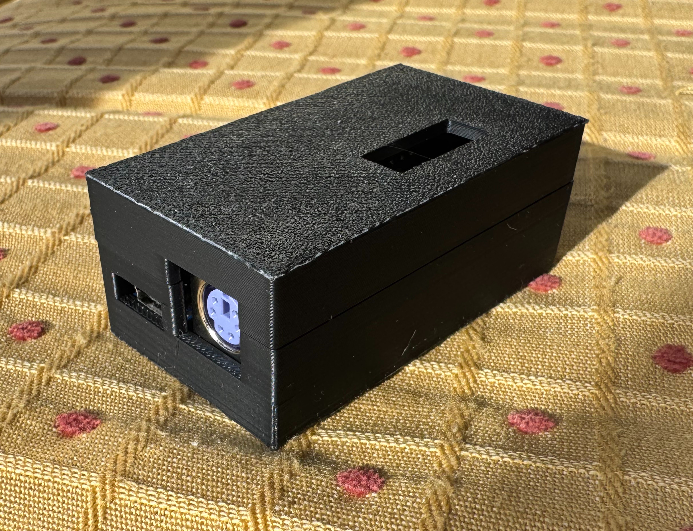
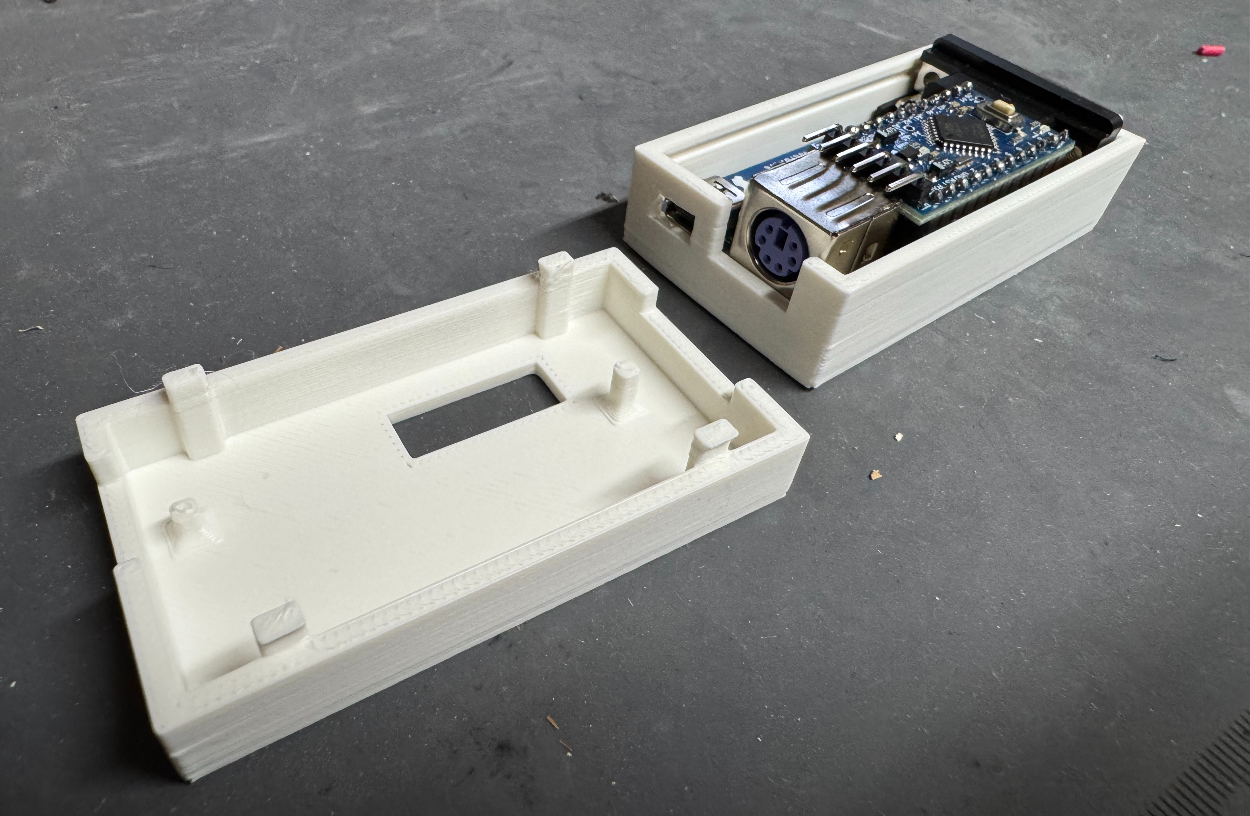
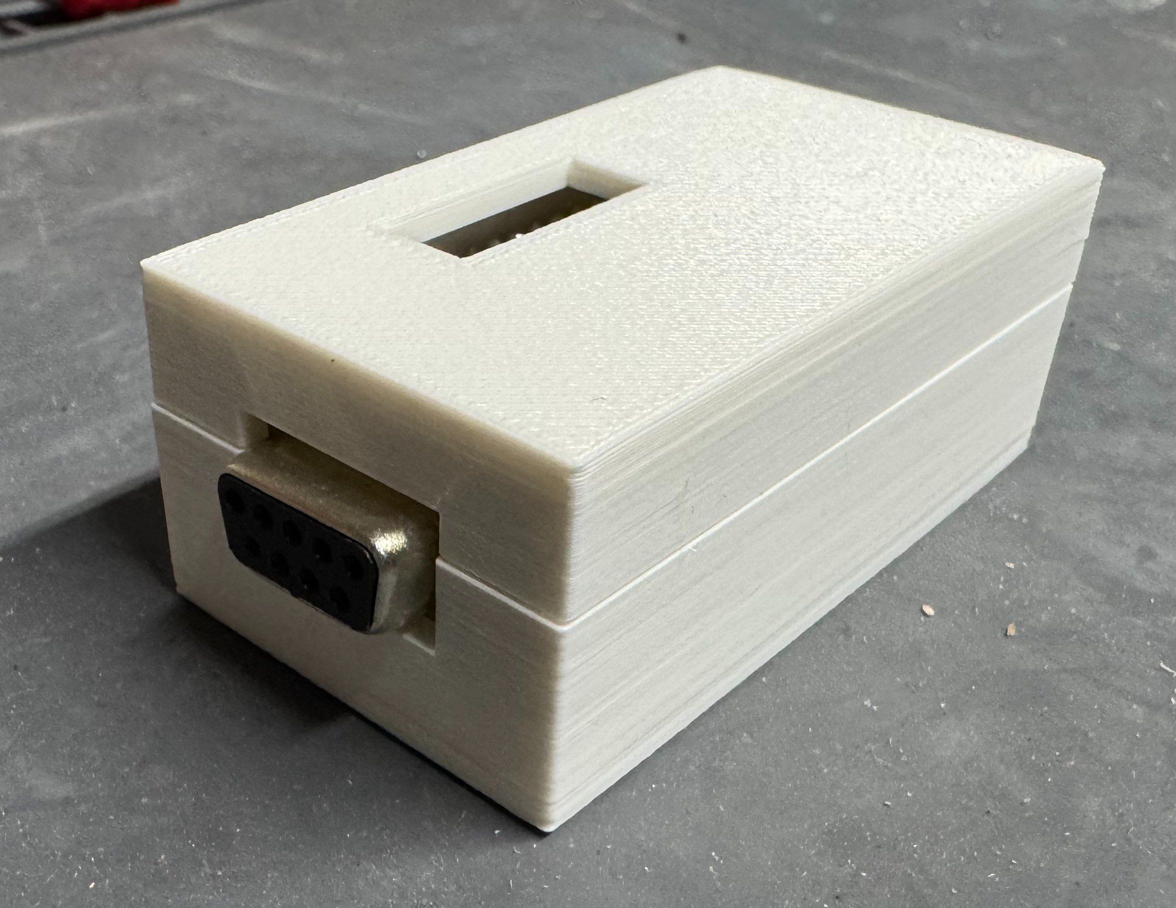
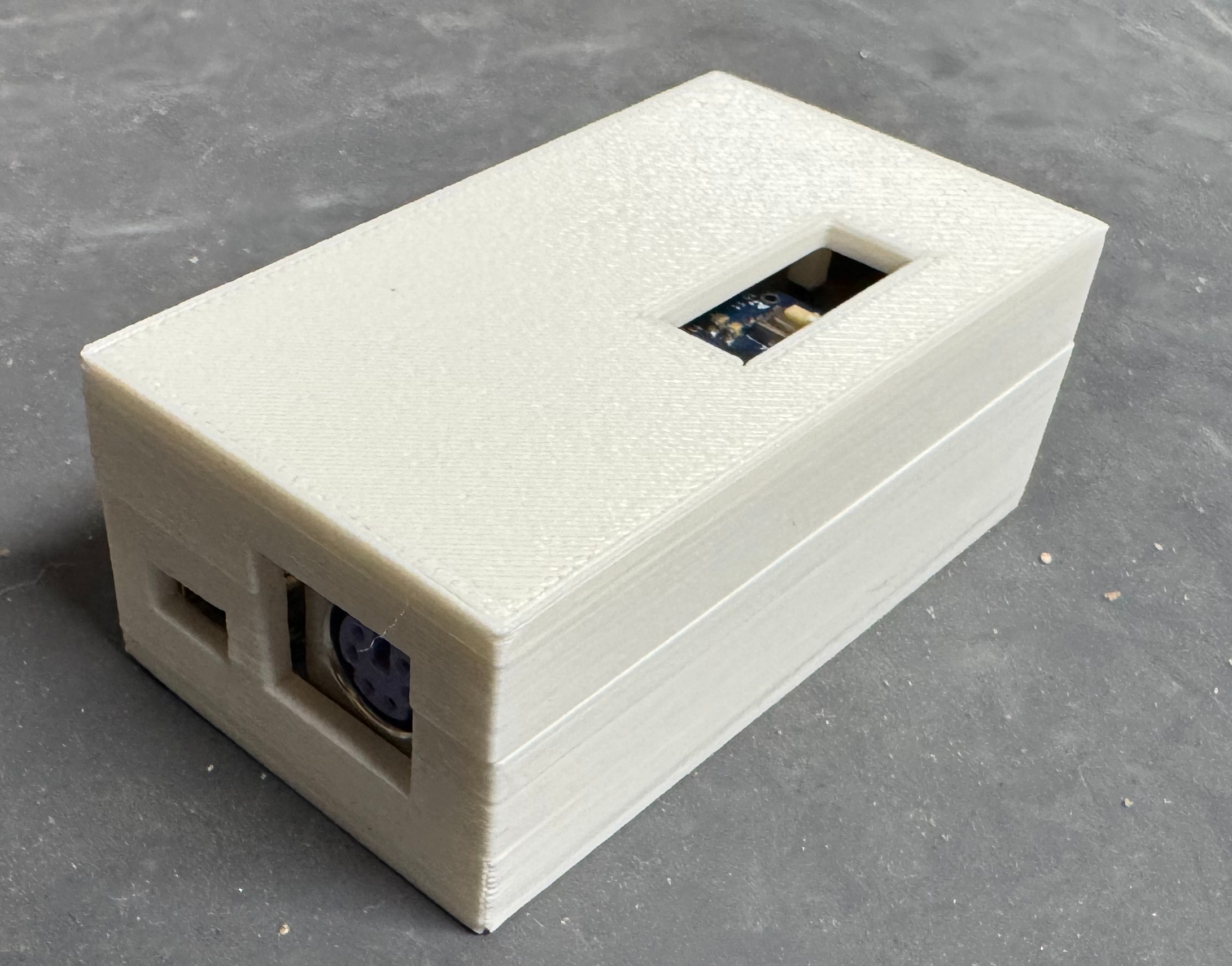
This is a device I will keep behind my old PC, and I didn’t want it to be a raw circuit board. I didn’t see any cases to 3D print, so I put one together. This was the first time I made a case that used little feet to snap the top and bottom half together; no screws! I also put little towers in to hold down the PCB in place. It took a few revisions, but I think came out nicely. There is also a little window to hit the reset button if needed. The black case was the second revision, the white case is the first.
A while ago I was working on a system to handle network boot operations. The main server is written in Java, and I needed to be able to read contents out of ISO files. The easy solution would have been to extract the ISO to the hard drive. I was trying to avoid that to save space; and with all the different images, not have thousands of tiny files littering the drive.
Then I found stephenc repo (java-iso-tools) for reading ISO files in Java. This library worked great! It had examples which helped me get started, and was fast to dive though a file. It supported the traditional ISO-9660 formatted files, which I needed, and I was good to go. Years later, the people over at CentOS and Redhat Linux had the idea to start putting giant SHA hashes as file names. Suddenly the disc images I was getting contained filenames that were 128 characters in length; and sadly java-iso-tools was failing to parse these names. To explain why, we need a bit of a dive into how the ISO-9660 standard works.
ISO-9660 is Developed by ECMA (European Computer Manufacturers Association) as ECMA-119, and then was adopted into ISO-9660. Thus, technically I was able to get the standards documents and investigate how ECMA-119 worked. Images start with a header; pointing to several tables, and the root folder file. The information about files on the disc span out from that root file. The root file, is the root directory on the image. From there every file is either a directory (with/without children) or a file which can be read.
The standard has had many changes to it over the years. While the original ECMA-119/ISO-9660 standard dates back to the start of the CD-ROM, over time people added to the standard. With PC’s at the time running MS-DOS and being able to save files to a FAT file system as 8 letter then 3 letter for extensions, the formatted needed added onto so one day CentOS could have 128 character file names. Some early additions to the format were Rock Ridge, and the Enhanced tables. When reading the first bytes from an image, there are several byte blocks which state which version of the standard they work with; this was forward thinking in this way. The basic tables help simple devices easily be able to read the discs. They can offer short file names, and point to the same binary data other tables later do. Then the enhanced tables can offer more information, and be able to add additional features to the disc. Some of these features can include things like file permissions.
At this point I had decided I needed to fix the problem and was going to write my own library to do it. While it sounds crazy, I enjoy writing these low level libraries. I started with the ECMA-119 standard, and going through the flow, like I was a CD-ROM device reading an image. I would later add on code for Rock Ridge, and reading all the enhanced tables, and even adding on a UDF parser.
I don’t want to spend too much time going through the standard. If you are interested: ECMA-119/ISO 9660 Standard, ECMA-167/ISO_IEC 13346/Original UDF Standard, Rock Ridge, UDF 2.60, there is a collection of the standard documents in depth. This post is more to talk about the project in general, and how I enjoyed working on it. A few constraints I set upon myself were I wanted it to be 100% in Java 8. That way it could be natively compiled if someone wanted to do that, wouldn’t just be connecting to some native binary tool, and would work with older Java code bases. The project currently targets Java 11 being the LTS out at the time I was working on it. I know there are many code bases out there which are Java 8, and I actually dont think there is any code except some tests using Java 9+ features. If someone had a Java 8 project, they could remove the tests and compile to 8. We live in a little bit of an odd time now, where a project like this targets more enterprise users who tend to be back on older versions. And at the same time Java 24 is coming out. I wanted to give high level classes that a user needing a simple tool could use; but at the same time have deeper level objects publicly available.
I was using this in the earlier mentioned network booting environment.There I can be building 100+ servers at a time; speed, small, and fast code were important. I ended up adding as test some performance benchmarks. I test the old library as my control, then I do normal file lookups as well as pre-indexed. I developed a system where certain heuristics of the image are taken and can be stored. Then you can feed in this initial “vector” I called it, of the image and a file vector. If the image matched the initial vector for a few characteristics, we could reasonably assume its the same image originally scanned, then instead of reading all the header tables, we jump to the location of the file vector with trust. This does leave it up to the developer to make sure they are matching pre-indexed images with vectors; but if you do, you can much faster serve files.
This project was fairly straight forward to test, I had many and there are many ISO images out on the internet. And plenty of them are Linux Images! I also had the older library which I could use as a control to test against. I ended up writing many tests which help when people send Pull Requests to make sure nothing has broken. This project I needed done to support what I was working on. There were a few places where I didn’t fully flush out the metadata, but left it to the end user to, if they cared about that data type. I spent a lot of time in Hex Fiend hex editor marking segments and trying to understand where code I had was breaking down.
Over the years of working in Open Source, and going to a technical college, I have seen many strong technical projects that are very impressive code, and can do a ton of interesting things. And then the developer focuses on interesting things they can make their code do, and spends no time putting documentation together. At the same time there are many project that get the job done, but aren’t anything special; these projects put a few documents together and maybe an example, and then get all the usage. The area developers hate to spend time, but can be the most valuable is documentation. That pushed me to spend a lot of time commenting the code, and writing a large README file showing how to work with the library.
I hope you will take a look at the project, maybe use it, and feel free to drop issues as they arise! I have been using the library in production for years now. It doesn’t get a ton of updates, because there hasn’t been a lot I need to add to it. When a PR or Issue arise I take care of it. And with the project being published under my work, I get a lot of automated PRs to help upgrade the library.
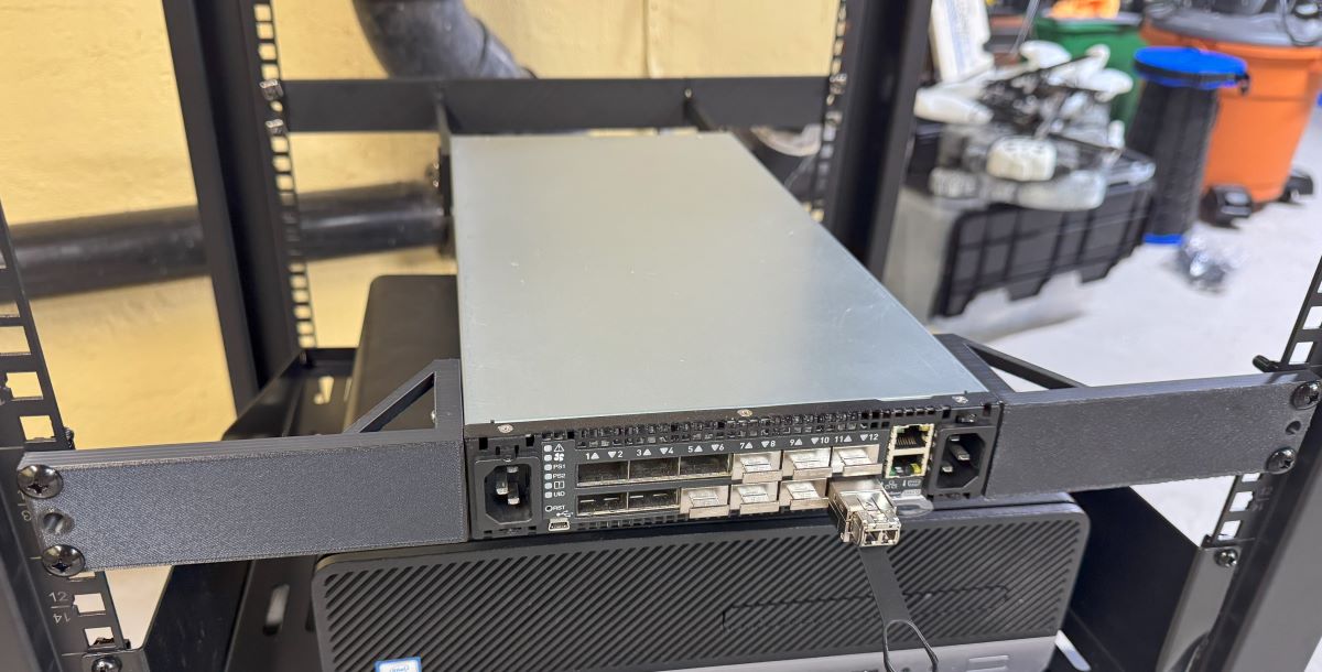
I have had two of these little Ruckus ICX7150 switches for years now. They are great little units with 12(ish) 1gb switch ports, and 2 SFP+ cages. My primary one hosts the Wifi APs in my house since the switch is also POE! I have bumped it to its latest recommended firmware on the Ruckus support page, and not had to do much of anything else.
Until recently when I went to SSH into the switch and Windows 11 built in SSH client no longer accepts SHA1 hashes that the switch gives. Or more specifically:
no matching key exchange method found. Their offer: diffie-hellman-group14-sha1,diffie-hellman-group1-sha1
There are two ways of going about fixing this, the first is to tell SSH it is allowed to access less secure clients, adding the following to C:\Users\your_user\.ssh\config does this:
HostKeyAlgorithms = +ssh-rsa
PubkeyAcceptedAlgorithms = +ssh-rsa
KexAlgorithms +diffie-hellman-group1-sha1
ForwardX11 no
ForwardAgent no
This isn’t the best, because we are just lowering generally accepted security practices, but it works.
The next thing I found out is that while 8.0.x is still the recommended release, FastIron 9.0 and 10.0 are out! One of the big recent features of 9.x is much newer crypto standards for SSH. 8.x simply doesn’t have them present.
I upgraded my switch from 8.0.95n to 9.0.10j_cd6; both the switch firmware, not routing. Apparently some releases have a “continual development” release which is smaller than a 0.0.1 release. I haven’t had any issues with the upgrade, it went the same as any other.
A quick note, these days if you attempt to scp it actually uses sftp as the backing protocol, to upload the firmware file to the switch use the following command:
conf t
boot system flash secondary
wr mem
reload

After the switch reloaded, which seemed to take a bit longer than normal with firmware updates, I was right back to my normal working switch and SSH worked happily.
I have been trying to get Kerberos auth working with WinRM to be the authentication for transport mechanism within Ansible. I want to configure a Window system, from the non-domain-joined Linux host that runs my automations. Getting these two hosts to talk over WinRM introduces a bunch of options and difficulties with each one. If you look at the table on Ansible’s website for Windows auth with WinRM, you see only a few options for a domain joined machine:
I specifically needed it for an Active Directory account part of my setup was creating lab machines and building domain controllers on the fly. Basic auth is out, Certificate is out, what is left is Kerberos, NTLM, or CredSSP. Then to throw another wrench in this, the Ansible host and server are in FIPS mode. At this point FIPS disables MD5. NTLMv2 uses MD5 internally, which means it does not want to work with an FIPS enabled machine. CredSSP is backed by NTLM hashes as well making Kerberos your only option.
I did not want to have to domain join my Ansible machine to my Windows Domain; this is a test environment. Through a bunch of tinkering I have found a way to run Ansible, and have Ansible use a local krb5.conf file, instead of your system one in /etc/krb5.conf.
It seems if you do not have the kinit.sh file, then kinit does not see the config. And if you don’t have the environment variable before the Ansible command, when Ansible goes to use GSS to connect to the Windows system, Ansible will not see the config.
Troubleshooting
Some fun errors along the way:
Server not found in Kerberos database
This means the server you are CONNECTING TO cant be found, usually this means the ansible_host is not the FQDN. Then when kinit is done it tries to connect to AD via the IP and that fails.
Kerberos auth failure for principal Admin@EXAMPLE.COM with subprocess: kinit: Cannot find KDC for realm \”EXAMPLE.COM\” while getting initial credentials
It cant find the krb5.conf file, OR under [domain_realm], your mapping has an issue
I use Solidworks Connected Makers edition to do a lot of my 3D Modeling. I had used Fusion 360 in the past, but they kept changing the license and what file types you could export, so I moved to Solidworks. As many posts from the community say, sometimes it’s like the company is trying to make you mad. Every year or so we get the next update, that you have to do because it’s a web-connected (for no reason) platform; and somehow the install breaks and won’t work. I spent a sometime trying to find all the different bits to delete to get it to install properly and wanted to document it. Once you get Solidworks in working order, it works well. It’s getting it there that is difficult.
I had a failed install, the Solidworks site thought the application was installed, but when I clicked run, I got “failed to launch application, not found”. I uninstalled anything related to Solidworks or Dassault Systemes. Then I found and deleted the following.
Go to HKEY_LOCAL_MACHINE\SOFTWARE\Microsoft\Windows\CurrentVersion\Installer\UserData
Search for “Solidworks”, I found items like \S-1-5-18\Products\0911033B9E8C8E647ABE3D57D2083CB1\InstallProperties, where DisplayName was “Solidworks 2020”, delete anything related to Solidworks at the Products level.
Even in the best conditions, on a fast machine it will take a LONG time to install, 3+ hours, looking like nothing is happening, I left it overnight. The x MB/y MB installed will not always progress for a while.
The install seems to install 4.5 billion MSI files, and then after each runs “.NET Optimization Service”; if your install is progressing, that service should periodically jump in CPU usage. My install halted at 76% 6122MB/14942MB installed for a long time; again, I left it overnight and it managed to finish.
I hope this helps someone. If others have issues or fixes, please leave a comment; maybe together we can get this program to work. In the end, mine worked after being left overnight, and now everything is functioning well with the 2025 release.
Update:
I went to reinstall and got the following errors:
Failed to get msi version for UpgradeCode [{B54313C8-7B46-297F-3AC1-85D9EFD5ECB7}].
Technical details:
The property is unrecognized
Error code: 1608
Invalid data in HKEY_LOCAL_MACHINE\SOFTWARE\Microsoft\Windows\CurrentVersion\Installer\UserData\S-1-5-18\Products\BE85C2B02A76B522062B1D99E055DD33
Action CheckInstalledMsiVersionAction from feature CODE\win_b64\SWXDesktopInsPreqWPT failed.
Action ID: SWXDesktopInsWPTInstalledAction
Failed to get msi version for UpgradeCode [{00F50064-7000-11D3-8CFE-1050048383C9}].
Technical details:
The property is unrecognized
Error code: 1608
Invalid data in HKEY_LOCAL_MACHINE\SOFTWARE\Microsoft\Windows\CurrentVersion\Installer\UserData\S-1-5-18\Products\E5A00A437891E38418011307471668D7
Action CheckInstalledMsiVersionAction from feature CODE\win_b64\SWXDesktopInsPreqVBA71 failed.
Action ID: SWXDesktopInsVBA71InstalledAction
I ended up searching for those hashes in the registry, “BE85C2B02A76B522062B1D99E055DD33“, and “E5A00A437891E38418011307471668D7“. Then deleting registry keys where a sub part mentioned Dassault Systems. After that I could progress with the install. Again, this seems to happen if you had Solidworks 2020 installed at any point.
My original version of this post I put together over a year ago. I was having issues with a 4 AP Ruckus Unleashed network I have in my house. I thought the issue came from 1 of the access points (APs) being WiFi 6(AX), and the rest being WiFi 5(AC); I wrote the post about disabling WiFi 6 on the 1 AP, then wanted to see if my issue were resolved over the next week. It was not. The issue was mostly around Apple devices refusing to roam. You can walk far away from 1 AP, and towards another, and you wouldn’t roam for a LONG time without manually disabling and enabling WiFi.
After more digging, and seeing people online chat, I was pointed to an Apple post (which has since disappeared) saying to move your “WiFi DTIM to 3”. DTIM (delivery traffic indication message) handles how often an access point echos out information about itself.
Changing this setting has seemed to make roaming on Ruckus work much better. Ironically, or not, this is one of those settings network engineers argue about. Here is a different Apple support post saying it HAS to be 1. Cisco, says the value should always be a 1 or a 2. Hopefully this info helps someone else if they are having issues, give it a try.