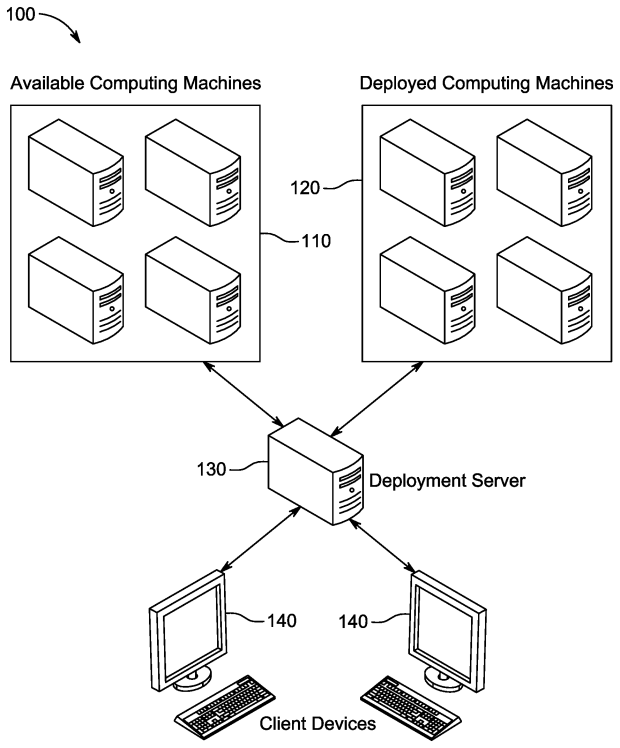
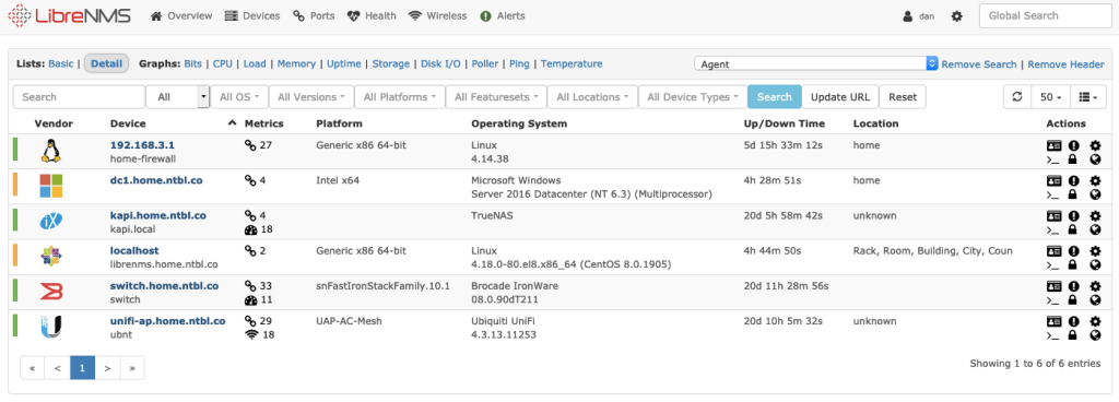
I started to deploy LibreNMS at home as a way to see all the systems on the network and any outstanding issues they may have. This is outside of log aggregation that I plan to do with ELK. Its been fairly smooth, running through the installation guide, https://docs.librenms.org/Installation/Install-LibreNMS/ for CentOS 8 (my standard Linux flavor at home for servers) was a breeze, then we just needed to add SNMP devices. I’ll post more when the whole system is together and I have a chance to put dashboard together, but for now I thought I would post some snags I hit.
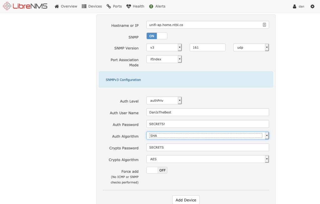
SNMP v3 is considered a lot more secure than older versions, so I am sticking with that wherever possible. There are a few commands you need for SNMP v3 in its strongest mode that makes sure no one can read the data, authpriv. Username, password, crypto password; password and crypto password also have different modes available. AES or DES for crypt, and MD5, or SHA for password hashing. Some devices now offer SHA-256, or SHA-512; LibreNMS does not, so lookout for that, a few of mine had to drop down to MD5 to find a matching mechanism. Every device defaults to port 161 with UDP for SNMP. You can also run SNMP over TCP.
Before I dive into different devices and how to configure them to work with LibreNMS/SNMP, I suggest getting familiar with snmpwalk as a command. It lets you quickly test and figure out if your setup is working, since if the settings are wrong in LibreNMS device setup, it erases them for you to start again. Some devices have you white list or select which IPs will be reading SNMP, testing from your LibreNMS host can save you some pain as well.
Windows
Windows Servers easily support it, and have a guide on the site. This page walks you through it, https://docs.librenms.org/Support/SNMP-Configuration-Examples/ and a lot of other devices. This is one where the easy solution is SNMP v2, Windows does allow easy white listing for SNMP servers, that made me feel good enough about the security over not having SNMP v3.
Linux
snmpd via the link above. Your stock LibreNMS host gets a premade config, that can be easily copied.
Ruckus/Brocade Switch on FastIron Switching Firmware 8.0.90d
The below commands add SNMP v3 to the switch. You need to make a group that you specify which privileges it has, then add a user to that group with the required password and crypt password that SNMP v3 in authpriv mode needs. Here 192.168.3.10 is my LibreNMS host, librenmsuser is my user, xxxxxxxxxxxx is my password and yyyyyyyyyyyy is my crypto password.
snmp-server host 192.168.3.10 version v3 priv librenmsuser
snmp-server group librenms v3 priv read all write all notify all
snmp-server user librenmsuser librenms v3 encrypted auth md5 xxxxxxxxxxxx priv encrypted aes yyyyyyyyyyyy
Unifi
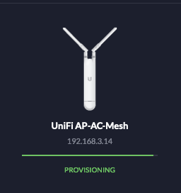
The Unifi devices gave me the most difficulty. Ubiquti has a few different product lines that are fairly different, thus searching wasnt always the easiest. I saw a few people say they dont really support SNMP or they only supported v1. Unifi device do support full SNMP v3 😀 They even have a cute icon in LibreNMS!
First I was in the Unifi controller attempting to set v3 info. As noted above there are several pieces of info you need to be able to enter into LibreNMS to get a SNMP v3 client to work. The Unifi interface was confusing because it just mentioned Username and Password?
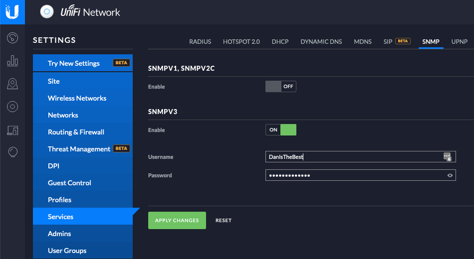
I thought this may enable SNMP on the Controller itself to read data for devices, but checking netstat showed no new ports or anything changing. So what was happening when I change this setting? That’s when I noticed my AP was back in Provisioning Mode because a setting just changed. ITS CHANGING THE AP ITSELF! AH!
The latest Unifi Access Points are just little Linux computers, if you ssh onto them and type “help” you get only a few commands, but a quick double tap of tab shows you have all the normal Linux commands.
BusyBox v1.25.1 () built-in shell (ash)


  ___ ___      .__________.__
 |   |   |____ |__\_  ____/__|
 |   |   /    \|  ||  __) |  |   (c) 2010-2020
 |   |  |   |  \  ||  \   |  |   Ubiquiti Networks, Inc.
 |______|___|  /__||__/   |__|
            |_/                  https://www.ui.com/

      Welcome to UniFi UAP-AC-Mesh!

UBNT-BZ.v4.3.13# cd ..
UBNT-BZ.v4.3.13# more snmp.conf
agentaddress udp:161,tcp:161
createUser DanIsTheBest SHA SECRETS! AES SECRETS!
rouser DanIsTheBest authpriv
Going back one level I was able to quickly find snmp.conf, which had all the settings I need, and here they are for anyone who needs them.
Unifi APs Use the following for SNMP v3:
- Port 161 in UDP and TCP
- Username is the username you made on the Settings screen
- Password is your password you set with SHA as the hashing method
- Crypto is the same as your password, in AES mode
- SNMP v3 auth mode is authpriv
Sophos XG
This one is also fairly straight forward, you need to go to Administration -> Device Access and set which vlans you want to have access to SNMP. Then go to SNMP at the top and setup your general info and then SNMP v3. This is one OS where for passwords they support MD5, SHA-256, and SHA-512; I had to use MD5 since I couldn’t get SHA mode on LibreNMS to connect to either of those newer SHA standards. I will also mention, when you commit your settings in Sophos XG it takes a few minutes for them to take effect. Set everything, then wait at least 2-3 minutes for it to start working, I was jumping around and couldn’t get my settings to take, then waiting a few minutes allowed it all to start working.