With CentOS 7.5, ioMemory VSL 4.3.3 kernel module would no longer load; I could not get it to recompile from source either. I tried a bunch of things including moving my CentOS 7.5 box to the EL7 4.17 kernel to see if that helped me compile from source, no luck. Then I found a forum post, https://forums.servethehome.com/index.php?threads/centos-7-fusionio-users-do-not-upgrade-to-kernel-3-10-0-862-2-3-el7-yet.19760/ where they speak of patching VSL 3.2.15. Using this and some playing around I got VSL 4.2.1 to work with my system. This method may work for some later versions, yet 4.3.3 had some other code changes that were causing it not to compile, so I used 4.2.1. Below are the steps to get a working ioMemory VSl 4.2.1 for Centos 7.5; comments if it worked or didnt are welcome.
Note: I did all these steps as my user, and not as root. My card is a FusionIO ioMemory SX350
A bit ago I picked up a PDP-8 replica kit, the PiDP-8. A kit can be picked up here http://obsolescence.wixsite.com/obsolescence/pidp-8-get-one . They are under $200, and I always found older computers interesting so I thought I would give it a shot. I also find The Digital Equipment Corporation and interesting tale of a far gone computing era. (There were t-shirts with the DEC logo on Amazon, but they are gone now)
The kit itself is a little smaller than the original control panel; photo from the creators blog above. This is not a real PDP-8, it is a front panel with a Raspberry Pi on the back of it. The Raspberry Pi has an image that is on the user forums (which are incredibly helpful as well as a nice community) which boots very quickly and dives right into the modified emulator. The design is wonderful and just uses the pinout on the Pi.
I got the kit, then ended up moving across the country and did not setup the kit for several months. When I got to building the kit (2015 version, pictured above) it was 2016 and instructions were up for both version. Not many differences except the switches, and how they are mounted. My version needed me to remove pins from each switch then mount each on a rod to keep them aligned. The 2016 version also has more authentic looking switches. I got the switch rod put together with no difficulties.
Then it was down to soldering the trillions, well it felt that way, LEDS to the PCB that came on the kit. Small soldering is not my favorite thing, so this took a bit; but in the end it was done and I was happy with it.
I wanted to test my soldering skills, or lack there of. I plugged the Pi in, and started the image. A few of the lights dimly came up, the rest of them just were dead. Darn this means somewhere it’s broken. I did some traces with a multi-meter, and couldn’t find the fault. Then I realized while it was plugged in the one integrated circuit that handles the LEDs were was getting very hot. I emailed Oscar who made the project and he quickly responded and said it sounded like the integrated circuit was dead and he would mail one the next day or so.
He was extremely helpful and kind, and I got the new chip a few days later. I had to go to Radioshack, (I was surprised I could find one! And its no longer there a few months later) to get a desoldering wick. I haven’t used this before, but it helped me remove the old chip. I soldered the new chip in, and powered it up. Instantly it all came online! I wanted to check all the LEDs, to verify if the OS was keeping some off, or if the circuit was bad, I got a diagnostic program that was written for this system. It did indeed show there was a error, and after resolding a small point then everything was working!
Now that the system works, and I sized it in the box; it was time to paint the switches! I covered half of them with painters tape and painted some brown. Then later did another coat. Then did the white ones so they were not off white or having the red dots on them.
After it dried, I cut a hole in the side of the case so that I could access the USB ports of the Pi. I just had a tiny hobby hack saw and a drill, these were not the best tools to cut the hole but it worked out. I also put electrical tape over the edges of the hole to cover up my handiwork. Then I mounted the PCB with wooden blocks for support into the box. I got some velcro with tape on the back so attach the front panel; that way I can remove it whenever I want for service and easily reattach it.
I got a power switch that is inline with a USB cable. That way I can have a switch to power on and off the device. Then I thought the blinky lights were neat, so I mounted it on my wall for now. It boots directly into OS/8 and in idling does a little light show.
The project came out well, and I am excited for Oscar to release his PDP-11 clone he has been working on in the background. I haven’t spent that much time programming it, but it is nice to have a piece of computer history above my desk. A big part of this project has been the awesome community over at the forum https://groups.google.com/forum/#!forum/pidp-8 and the kindness of the project owner and his willingness to help. Oscar’s blog has some cool stuff as well, http://obsolescenceguaranteed.blogspot.com/ .
I recently restored my Compaq Portable II. If you haven’t read Open (Link) about the forming of Compaq I would suggest it, I highly enjoyed it. In doing so I thought I would transfer some files to the 286 via serial, instead of taking the Compact Flash card it ran on out of the adapter, and then copying new software.
I started my journey thinking I would use the old Microsoft Interlnk software that came with MS-DOS 6.22, and then perhaps a virtual machine on laptop to serve the files. The laptop I had on hand was a Macbook Pro, I thought I could do a MS-DOS vm, then hook the USB serial adapter up to the vm allowing MS-DOS to see it as COM1. This turned into a giant headache, VMware and Virtualbox (I tried both) kept giving me errors. They really didn’t like the USB serial adapter (who does), after a few hours of playing with it I made a silly decision of: the easier way would be write a new InterLnk server in Java and let my modern OS talk to DOS directly.
I spent some time configure two Vmware Fusion vms’ to have virtual serial lines go to named pipes. Then I had socat interconnect the two pipes and log the traffic, (I put the command below if anyone is interested). On one hand, I found it interesting researching debugging serial communications using virtual machines. On the other hand, after more time than I care to admit, I didn’t see a clear pattern to the serial data, along with was getting the data going between the systems but not in a super clear format, Wireshark has spoiled me. I finally decided it was time to try another plan. A quick detour to try to decompile the app made me more confused than ever, and we were back searching for a new method of connection.
After researching different methods of serial file transfer, such as xmodem, ymodem, and Kermit; I thought I would give Kermit a try. I have used xmodem for dead Cisco devices, and thought Kermit would be easiest to server from my Mac. It allows things like packets in the protocol, which makes it be able to speed up and slow down transfers as the transfer goes on.
To configure the server on the laptop I used Homebrew, installing with:
brew install c-kermit
Then I loaded the app via the Compact Flash card for the Portable. I got Kermit for DOS off of http://www.bttr-software.de/freesoft/comm1.htm . Version 4 for DOS works mostly the same as version 9 from Homebrew. The app lets you change directory to a folder you want to operate out of, set your connection settings, which I have below. Then you hit the command “receive” or just “r” on one side to receive. The other side then pushes whichever file you want.
Client
set port com1 # Or COM2 or whatever the port is
set carrier-watch off # Assume there is no carrier signal
set speed 57600 # Or whatever the speed has to be
connect
Server
set port /dev/tty.usbserial
set carrier-watch off # Assume there is no carrier signal
set speed 57600 # Or whatever the speed has to be
connect
I selected 57600 because I was not sure if the Compaq could handle the next jump to 115200. This page has a lot of info about setting up the program, there are a lot of dials and knobs that can be moved. http://www.columbia.edu/kermit/k95faq.html
You can bring up a serial connection between the two and just type messages, but in the end I remembered how slow serial links were. I ended up powering off the system, pulling the Compact Flash card and then loading most files that way. Sort of felt like cheating, but when transferring the Windows 3.0 install files were going to be a 15 minute plus affair, I want to the good ol’ USB 3.0 Compact Flash Reader.
Someone years ago gave me a Compaq Portable II. I always have loved this machine. Coming from the days of “luggable” computers, it weights over 20 lbs, and has a tiny CRT. The model I have has a “Type 2” (20MB) hard drive, and 640KB of RAM. For a little bit I thought my parents had accidentally thrown it away, as I was storing it at their house. Then it was found again and much rejoicing was had. The system is a Intel 286, with no math co processor.
Recently the one I have has come down with a few problems, so after seeing a brave young soul take their apart (https://www.youtube.com/watch?v=DqaWCobAbQ4) I decided I should give it a go. First the battery on the motherboard started to fail, not only resetting the clock when it lost power, but also forgetting the type of hard drive it had. This made it so every time the system was used, you would boot a 5 1/4″ floppy of MS-DOS, then change floppies to the Compaq Diagnostic disk, and configure the BIOS, and finally go back to the MS-DOS disk. I was lucky that some places still have the disc images online; http://yesterbits.com/2012/09/23/booting-the-compaq-portable-ii/ . I attached those disks to the bottom of this page just so there is another mirror online for others.
I knew that the BIOS battery needed replacement, but when I recently turned the system on the old hard drive had finally given up. At about 30 years old I can not blame it. A fun fact about the drive in this system, it is actually a MiniScribe MFM hard drive (more info here http://www.seasip.info/VintagePC/compaq2.html) that has a MFM->IDE conversion board on it. The drive is also shock mounted, this computer is portable after all! Knowing that, I decided it was time to swap that dead drive for a Compact Flash -> IDE adapter. This would be a size and speed improvement over this old hdd. Luckily someone else had already attempted this! http://tkc8800.com/post/compaq-portable-ii-restoration
Armed with all that info (and the manual – http://www.minuszerodegrees.net/manuals/Compaq%20Portable%20II%20-%20Maintenance%20and%20Service%20Guide.pdf) I took the system apart, and very carefully avoided the high voltage CRT area. After getting the top cover off, then the front bezel; I needed to remove was the floppy and hdd caddy. I removed the cover of the caddy as well as the rear card cover. Then I could get access to the ISA cards. This system has the standard IDE control board, the video board, then a blank, and finally a board called EVEREX with a crazy connector. I have no idea what that last board ever went to. Some quick googling says it may be a tape controller card, or an special external monitor. My plan was to use the third slot to put the Compact Flash adapter, that way I can access it externally. (Here is it being tested)
I got a 8gb card off Amazon because it was fairly inexpensive and that would be so much more than plenty. After looking through all the options the system gave me, I settled on a “Type 41” hard drive even though the system auto detected it as a “Type 14” This gave me around 250MB of storage, for my uses that was plenty.
Now to replace the BIOS battery. The manual covered this. The battery is under the cover, where the extra RAM would be, IF I HAD IT. I took the bottom off, cut the zip tie that held the battery, and replaced it with one off Amazon. That first battery lasted about 25 years before it finally stopped remembering, I think that is a good battery.
One thing that stood out was the battery. I got a battery from the same company as the original, photo above; the battery on the left is the new one, the one on the right is the 30 year old battery. These batteries are 30 years apart, yet they look almost identical. I think that’s hilarious and interesting.
It came time to close up the case, mostly replacing metal covers around the system then placing the cover over it all. I ran into a little problem replacing the ISA card cover, there are little feet that hold the cards in place, but my IDE cable and power cable were in the way. I had to push the cables closer to the ends of the cards to make the cover fit. Then I used plastic twist ties to hold the power cable in place.
Right before sealing it up again, I cleaned the cases because it was already off. Below are some photos of the final system. The next thing I would need to do is replace the keyboard cable, the plastic is chipping off. I did a quick glance at how hard that repair would be, the issue is the cable goes into the monitor compartment (high voltage capacitors are scary) and I will need to solder a new cable to the keyboard/cable which is more than I was looking to do in this first repair session. I also one day should get a ISA RAM expansion card. A giant benefit to having the Compact Flash card slot on the side, is if I want to load more software I can just take the card out and plug it into a modern PC. I also can create a VM and use that card as the hard drive, making for easy dsk file image installation. This is close to infinite times faster than serial connections to transfer files.
This system has a Intel 286 with 640KB of RAM. To run Windows 3.1, you need extended memory; which I currently do not have. If I had a 386, then I could create a page file, and use disk space as memory, but a 286 does not have this ability. To have some version of Windows I installed Windows 3.00a off of https://winworldpc.com/product/windows-3/30, they have a great collection of Windows versions, with different languages and builds. I have a ton of old Windows versions in packaging, but this was simply easier. I also got a MS-DOS 6.22 bootable installation image off of https://www.kirsle.net/blog/entry/ms-dos-and-windows-3-1 and installed that as my base.
All in all, this PC got some much needed attention and is now back to its old self. The Compaq Portable II is back to its old brilliance with Windows 3.0 on its 250MB SDD (technically it is a SSD), 5 1/4″ drive, and tons of games, as it should be.
Random bonus: I enjoy the Compaq Setup Disk load screen, it has a animation with the logo that uses the slow refresh time for an interesting effect. Below is a Imgur upload of it.
I was very excited to see Susan Kare borrow of of the mini Macs from a friend and give it a shout out on Twitter! These kind words from someone responsible for a lot of the original Macintosh design are quite humbling. 🙂
In building the project I wanted the computer to have the closest to the original feel as I could get. There were a few difficulties in the project, from the TFT screen, to the OS configuration. Yet in the end, I got a cute little replica running on top of a Raspberry Pi. I am not trying to break copyright, or profit from this. I simply do it as a fan of good hardware and past operating systems.
To start I want to mention that there are areas of this “guide” where I have been short, if you are unfamiliar with Linux, some of the parts in this config may give you problems. This project includes compiling code, adding scripts to boot, and configuring systems like VNC.
I loaded the standard Debian install onto a SD card to start (which at the time was Debian 6 or 7), then I started investigating the different original Motorola Mac emulators. The two main ones I found were Basilisk II and Mini vMac. Basilisk offers features such as Color, networking, and advanced features over Mini vMac. A very useful feature that Basilisk has is supporting a shared drive. You can tell the emulator that a folder on your Pi or any PC should show up as a hard drive in Mac OS 7. That way you can easily download games/software from archive.org or other locations, then load it onto the virtual system!
Mini vMac did offer greater compatibility for apps, while only being black and white, it seems to do a much deeper level of emulation; this makes it slower, but some apps that wont work on Basilisk will work on it. My solution in the end was to put both of the emulators on the box, pointing to the same virtual hard drive.
A script wraps the system, by default it auto boots into Basilisk, but if you “shutdown” the Mac in the emulator, you get a options screen that will allow you to switch modes the emulator is running in, the emulator itself, or some other settings. Some of the other settings including pairing Bluetooth, shutting down, or dropping to the console.
These files are available under https://github.com/daberkow/minimacparts. There is a SYSINIT script that starts the script, aka the wrapper, and gets the session started under the “pi” user, this goes in the /etc/init.d folder. Then there are folders for the different emulators in the /opt/mac folder.
Note: I used the current Raspberry Pi Debian build when I did this project, which at the time was using SYSINIT over the newer SystemD. If you want to use a newer build (which you probably should) you will have to translate my crummy SYSINIT script into a SystemD script. Feel free to pull request the repo! 🙂
One of the larger issues that had to be overcome was screen scaling. The screen I used is 480×320, but the original Macintosh resolution was 512 × 342. This had some of the emulators either cut off, or scrolling around the screen when the mouse got to a corner, which was not great. I could run the emulators at a smaller resolution, but some software was designed with that screen in mind and applications were cut off!
My solution was to use VNC, the system starts the emulator in a VNC session running at the native resolution, then the Pi screen connects to that session and enables scaling mode, shrinking it to the proper size. This way VNC worries about all the scaling, at a minor speed loss. I looked at different X configs to try to do the scaling that way, but the way this screen works, it gets upset and has problems very easily. The screen does not have a scaler of any sort, so you HAVE to send that resolution of 480×320 to it. The VNC solution works well. The different emulators have VNC config files that are copied to the running config right before its run depending on the emulators properties.
At this point we should discuss dependencies; TightVNC server was used for VNC. A quick minor note about VNC, you need to config the VNC users password, and then setup the script to auto-login with that password for the above script to work. Bluez Bluetooth stack and utils were used to be able so use Bluetooth peripherals. Basilisk and Mini vMac were compiled from source on the Pi 2 so that I could squeeze the most performance out of the little PC. Also its hard to find the latest versions ARM compiled online.
The authors website offers a nice little service to have the website compile to code for you, or you can compile it yourself. Depending on your screen and how you want the app to start (a lot of those settings are hard coded in at compile time) http://www.gryphel.com/c/var/index.html.
I made one virtual hard drive, that both emulators used. Luckily they use a compatible hard drive image format. I set the first image up on my desktop just because it was easier. Then copied it over once I got the image in a good state. For years Apple gave out for free on their website Mac OS 7.5.3, then after a website update it seem to break a lot of the links. A few still worked but most over the years have stopped working. A lot of different sites have mirrors of those disks available though, if you search “System_7.5.3_01of19.smi.bin”, that should bring you to one of the mirrors. The one other thing you need is a ROM for a original Macintosh. I have some classic Macs at home, and you can dump the ROM from those. Or there are sites out there that have them hosted, I would guess that would not be to hard to find.
I put the virtual hard drive, and the ROM in a folder called “Shared” in the /opt/mac directory. You may have to tweak some of the configs/scripts to get everything working your way.
Once you get it working, there are a ton of games and pieces of software on archive.org for the old Macintosh, just make sure you get the 680*0 versions not the PowerPC versions. There are also a ton of abandonware sites, since half the companies that made this software are out of business, I doubt they will mind you taking a look, though legally its a grey area.
Those are the basics for how I got the system setup. One item that gave me a bunch of problems was the TFT screen. At the time you needed to load separate kernel modules and configure boot parameters for it. I think newer kernel images have added this, so that should be a simpler task for everyone.
HipChat 4 has recently come out, and then shortly after it was released to my companies internal HipChat server. Being a Linux user I hoped that the aged HipChat 2 client was finally updated for Fedora or Red Hat or CentOS 7 so I could just use yum to install it. When I went to the download page the old yum instructions were replaced by only Ubuntu/Debian instructions! After playing around with the Debian package and getting it to load, I thought I would look at the repo a little more. Low and behold, Atlassian is making a yum repo! Just not publishing instructions on how to use it! The downside is they seem to not be signing the repo, but the code below works with yum to download the latest version.
The units themselves are laser cut acrylic. The front face that was put on the painted units was 3D printed. The designs for those pieces are on my GitHub page, https://github.com/daberkow/minimacparts . The original design was a tad bit smaller than the final unit. I ended up making it exactly about 1/3 scale, then realizing that there was not a screen on the market to do what I wanted to do. When I moved up to the 4″ screen, the resolution went up to a incredible 480×320. There were a bunch of issues around that resolution that I will get into in a later article.
For the Raspberry Pi I used a Raspberry Pi 2. The first version I made had a Pi 1 in it, and I ended up upgrading to the 2 just for the speed and added cores. With the system running a emulator, core 1 can get used up by that; having more available made sure things like SSH didnt lock up.
I designed two brackets, one set that holds the screen in place, and another that mounts the Pi to the inside of the case. The screen mounts are just two bars that are the exact with of the screen and help mount it inside, while leaving the port available for the IDE cable. The mount for the Raspberry Pi made it easier to take the Pi in and out of the case when building the unit. And a nice list so the Pi doesn’t get glued or screwed right into the side of the case.
For the front USB port, I got a USB 3.0, 6 inch cable. The most important part of this cable is finding one with a 90 turn at the end that does not stick out a lot. The Raspberry Pi is mounted in the end to the side wall of the case, and there is not much clearance. A USB cable that comes out from the top of the Pi is better as well. I ordered the wrong one for this last build, and then had to bend it a bit so it wouldn’t push against the side of the case.
A simple micro-usb extension cable was used for powering the Pi. The female jack goes to the back of the case, so that the unit can be powered. Again, the 90 degree male plug was important because that side sits right next to the screen. Audio was a random 90 degree 3.5mm extension cable off amazon. The first unit, the clear one, had a different make than ones i got later. Some of the later units had a splitter instead of a single extension. The original idea was to have a speaker inside for the start up sound. That quickly added to the complexity and was cut from the final project.
The networking port was important so that I could easily add new programs to it. The systems also had a tiny wifi receiver, but I figured hard wiring was also easy. That was a custom keystone jack to a RJ45 port.
I mentioned in Part 1 that the screen was connected to the Pi via a IDE extension cable. After looking around for other solutions that worked cleanly, this was the best one. The cable can handle the frequencies, and was easy to find. It also doesn’t do any flipping of pins or roll-over shenanigans.
To bring it all together, super glue was used, not the most glamorous, but strong and holds. I made a few little tools to help me try to put better right angles together when gluing the cases. Those didnt always work out great.
To wrap up, I will go over my build order, just in case anyone decides to try to make one of their own. I would first get the front piece, and glue that to the side walls. Let that dry for a few hours at least, superglue likes to dry fairly fast, but I wanted it to be solid through and through. Then I would add the bottom front panel area, and the sliver that goes between the front bottom, and that bottom panel. After I put the bottom of the unit on, I would stop working on the main body. Now its time to get the screen, with it powered on and working with the Pi, line it up to where it looks good in the cut out.
After I have found the spot the screen should go, put the brackets on it, and glue it into place. This has to be a little carefully done, any spare glue that drips into the screen can make it look bad. Once the screen has dried, getting the mounting arms for the Pi bracket, and gluing them in place was done. There is not a real science to where it went, I would put the whole Pi sled in, then see where it seemed to work well with all the cables attached. Then sharpie those spots and glue the arms down, watching them long enough to make sure they didnt fall over. Once that was done, and I felt good about where the Pi was, I would glue two tiny blocks I 3D printed to hold the Pi sled in place.
Gluing the front USB isnt too bad, its putting it in position then gluing the edge of the extender into the place it should sit. The hardest part is not getting glue in the connector, and doing multiple layers so that it doesnt move with normal user use.
Getting the back to stay in place was my least favorite part. There are little L brackets I 3D printed that the back could screw into. They work well but lining them up and gluing them into place, and not the back itself was tiring. I would tighten the brackets a fair amount to the back plate, then get the plate into position and glue the bottom two brackets into place. Then I would do the top two. At this point gluing the different connectors into the back ports isn’t too bad. I also made brackets for them, the brackets are bigger than the whole so that it covers the whole port when the piece is in it. These brackets weren’t held with little arms like the Pi, just glued into place.
Finally the top was glued in, and then the last little top slant area. The screen I mentioned getting before may not be available from Amazon, but there are a ton of others that are all seem to be made by the same place, then had another brand stamped on them. For the last build I did, I grabbed another brand (link) and it worked with the same drivers out of the box.
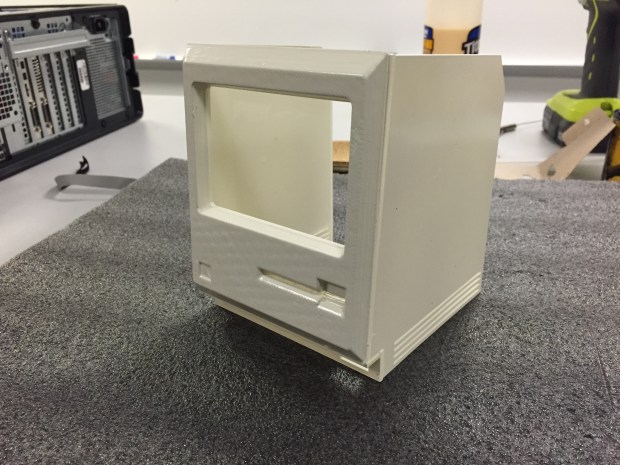
I saw online someone who made a tiny Mac (The Verge) and thought it looked like a neat project to attempt. I started by selecting the original Macintosh as the template I wanted to emulate. Several people had made 3D models of the original Macintosh over on thingiverse.com, I used a combination of those and other sources online including photos to make a cleaned up model for myself in Sketchup. After having that model I went about breaking down how I would make it.
I recently have been using laser cutters for fun at TechShop, so I made the body of the machine out of clear acrylic. Then 3D printed a face plate that was glued onto the acrylic case. After that, it was painted with several coats of spray paint. I left the back door off so that I could work on installing the electronics, and setting up the software. That will be another article later.
The first unit I made was for myself, then two more for friends; the original one never got painted, I thought the clear body was neat and showed off the internals. It also gave me a good model to hold when working with the opaque other units.
Mini Mac v1
Each unit had a little screen that connected to a Raspberry Pi via a ribbon cable. Then a USB port in the front where the old unit had a keyboard port. The back had a ethernet port for updating the system itself, audio out, and micro-USB port for power. One of the hardest parts of the project was finding a ribbon cable that could handle the frequencies and work between the screen and the Raspberry Pi. A lot of the GPIO ribbon cables online actually flip what wire is in the 1 position with its neighbor; my solution was a 6 inch IDE extension cable. The cable can handle high frequencies, as well as fit the pin out perfectly.
Example Painted Side
After testing several different color paints, I ended up using Rost-Oleum Ivory Bisque semi-gloss as the beige shade. All the sides were glued together except the back, The back was held on by tiny brackets that were 3D printed and then screwed into. This allows access to the inside without breaking glue somewhere. Originally I was going to attempt to put a little handle on it, but that increased the complexity; in the end the top is flat.
All the laser cutting and 3D files I used I tracked with Git over at https://github.com/daberkow/minimacparts . I will put a few photos of the clear unit below, and of the final unit. Then later post another article about the electronics, and software to run it. There are also photos of the many many attempts at different sized bodies and painting side panels. My original model was almost exactly 1/3rd scale. Then I had to make it a tiny bit bigger because of the screen I used.
Standard disclaimer that I do not own or hold any rights for the Macintosh name, or Apple logo. I do this as a fan for fun.
Parts:
Screen, JBtek® Latest Version 4 ” inch IPS Display (Super TFT) 480×320, (Amazon)
I recently have been working on a system automating CentOS 6 installs for servers. When upgrading to 6.6 my test environment (VMWare Fusion) stopped working. I got a hard kernel panic and halt on loading. Now VMware forums and CentOS site, have posts about work arounds for this. A bunch of them are complex and involve changing modules around, and other files. There is a very easy fix for this, and its detailed below.
NOTE: I am running VMware Fusion, so I will open a package, in Windows and Linux you dont have to do this, just go to the folder.
Stop the VM
Find the VM files
For Fusion there will be a %Your VM%.vmwarevm file, you have to right click that and “Show package contents”
There should be a %Your VM%.vmx file, open that with a text editor
If you are on a Mac, or other machine that likes to do smart quotes, make sure to use a program like vim or Sublime Text that doest add “smart quotes”
A line will read: ethernet0.virtualDev = “e1000e”, change that to ethernet0.virtualDev = “e1000”, just remove the last e. This changes the card from a E1000 in enhanced mode to a normal one. Now CentOS 6.6 will boot.


 Several people had made 3D models of the original Macintosh over on


