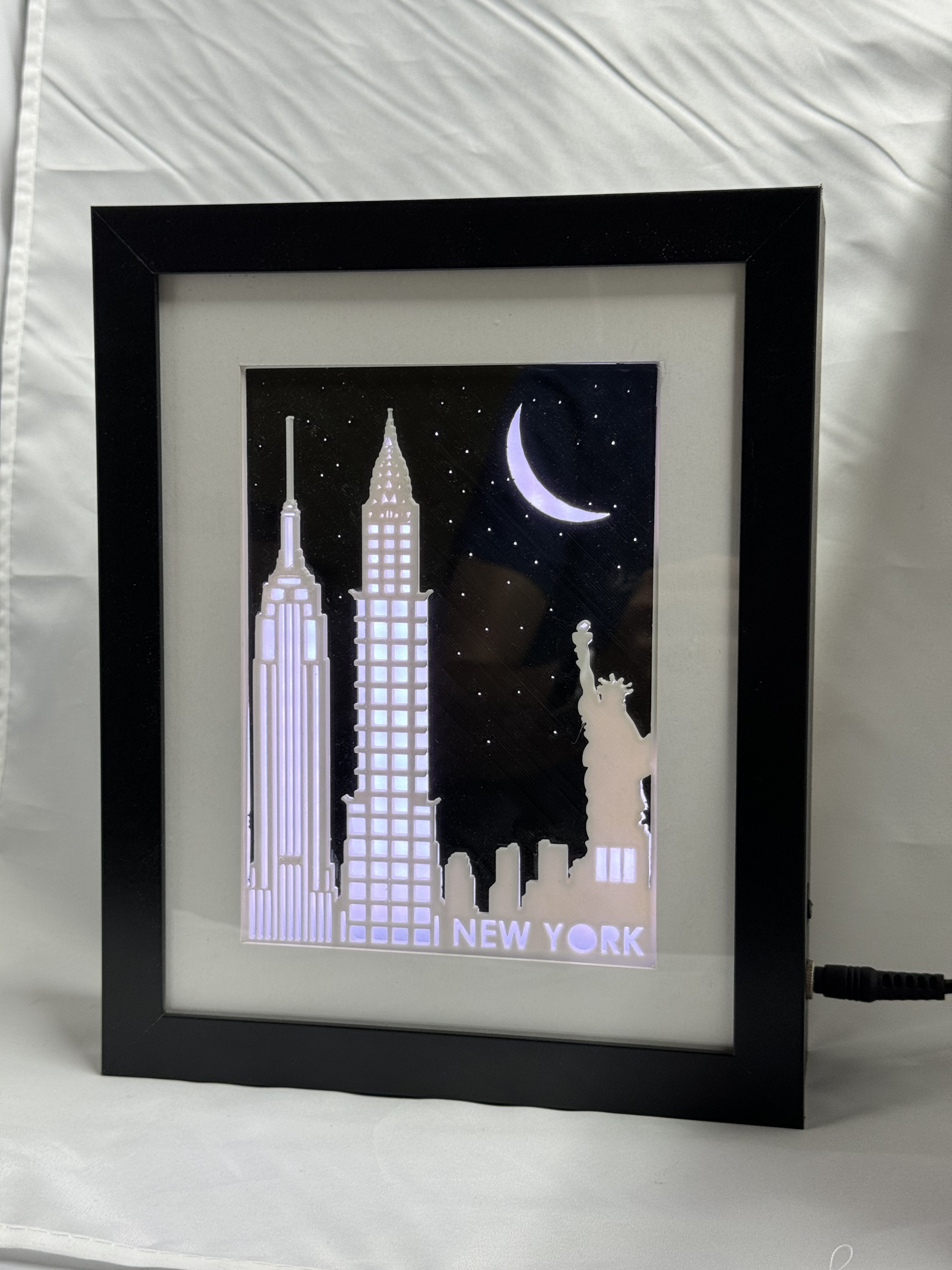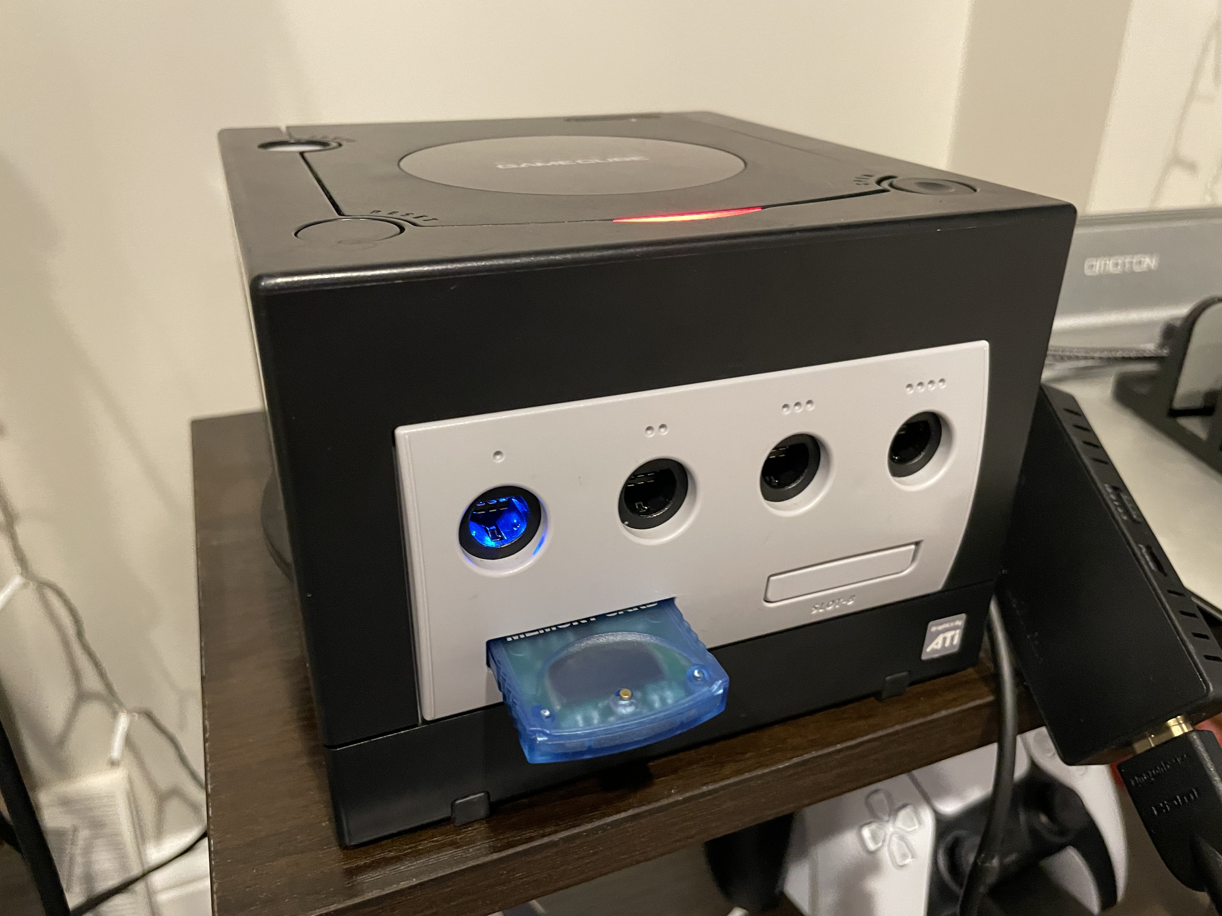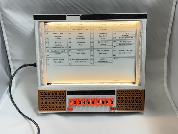
I have always loved audio as a medium, I don’t know why. Starting with playing around with an old stack stereo growing up; learning I can record a record onto a tape blew my young mind. I have done several projects around audio. Continuing on that, I love the classic Jukeboxes. They come from an era before microprocessors. Before you could just put a chip in something. When real mechanical and electrical engineering made things work. To pay homage to that I have been working on a similar looking device to an old Rock-Ola 507, but… I just put a microprocessor in it…
All 3D Models and ESP32 code is on Github.
Design
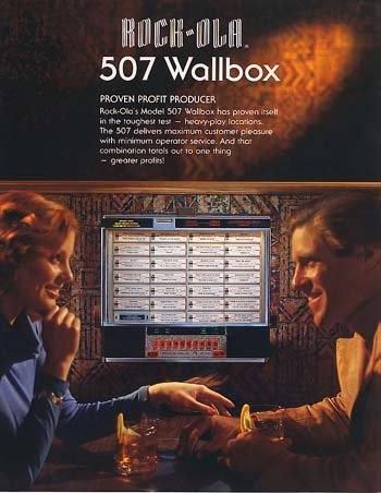
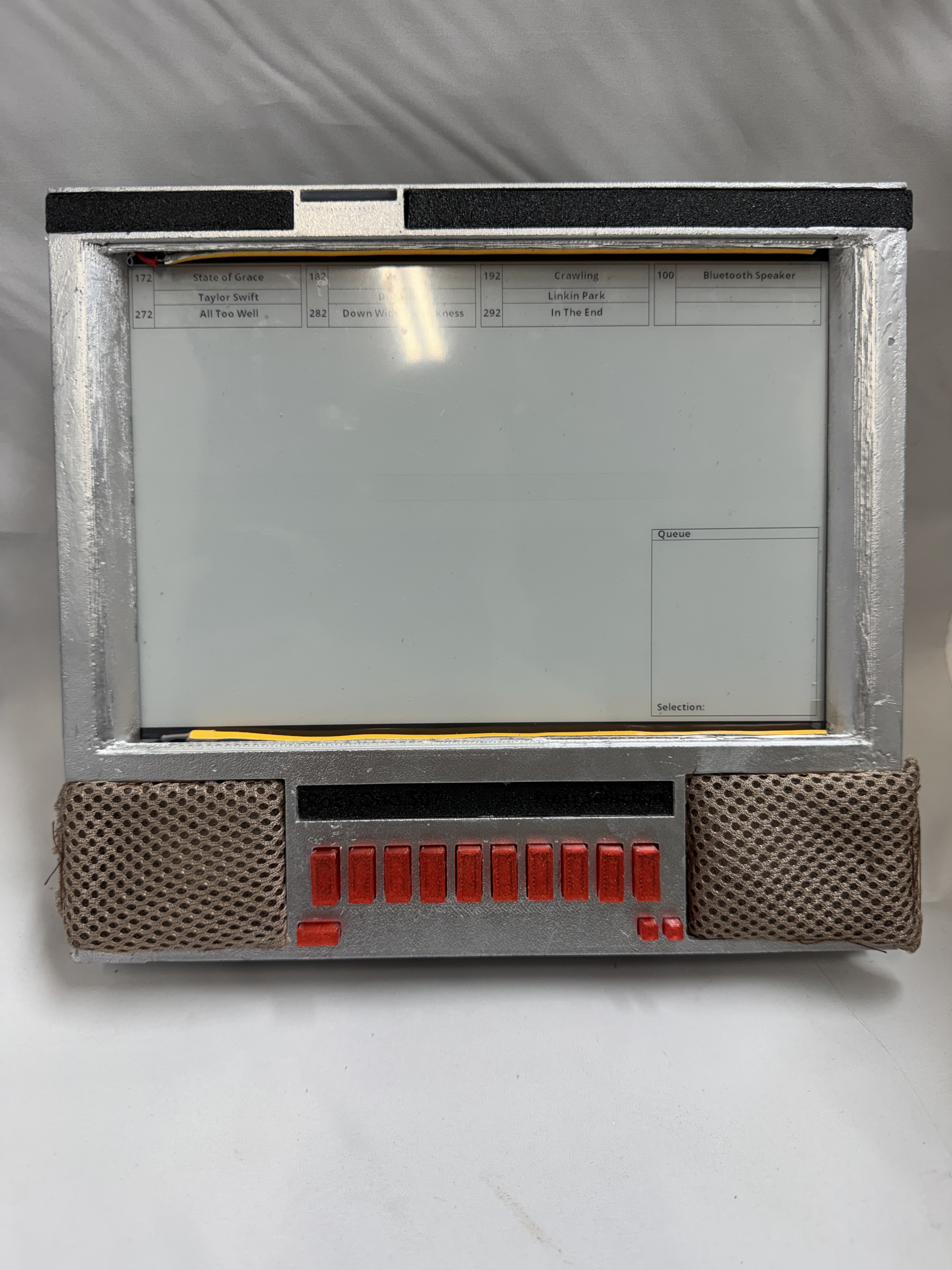
The Rock-Ola 507 was a table side music player for diners and restaurants. Rock-Ola had many models of “wallboxes” that connected to jukeboxes. I always liked the older 1548 models, but those have a lot of moving parts and many buttons. Instead, I opted for the simpler 507. I called mine the Rock-Ona 507.
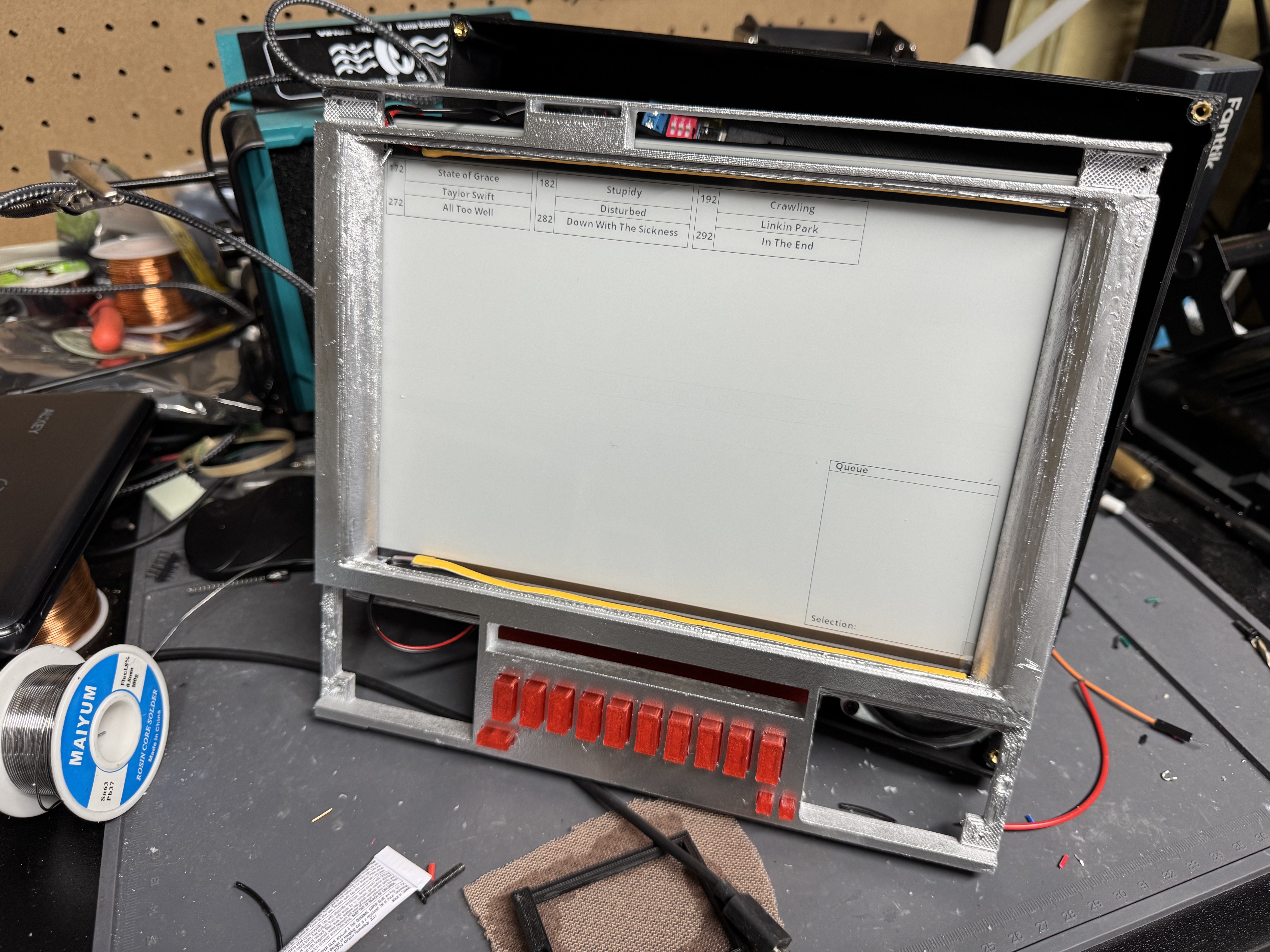
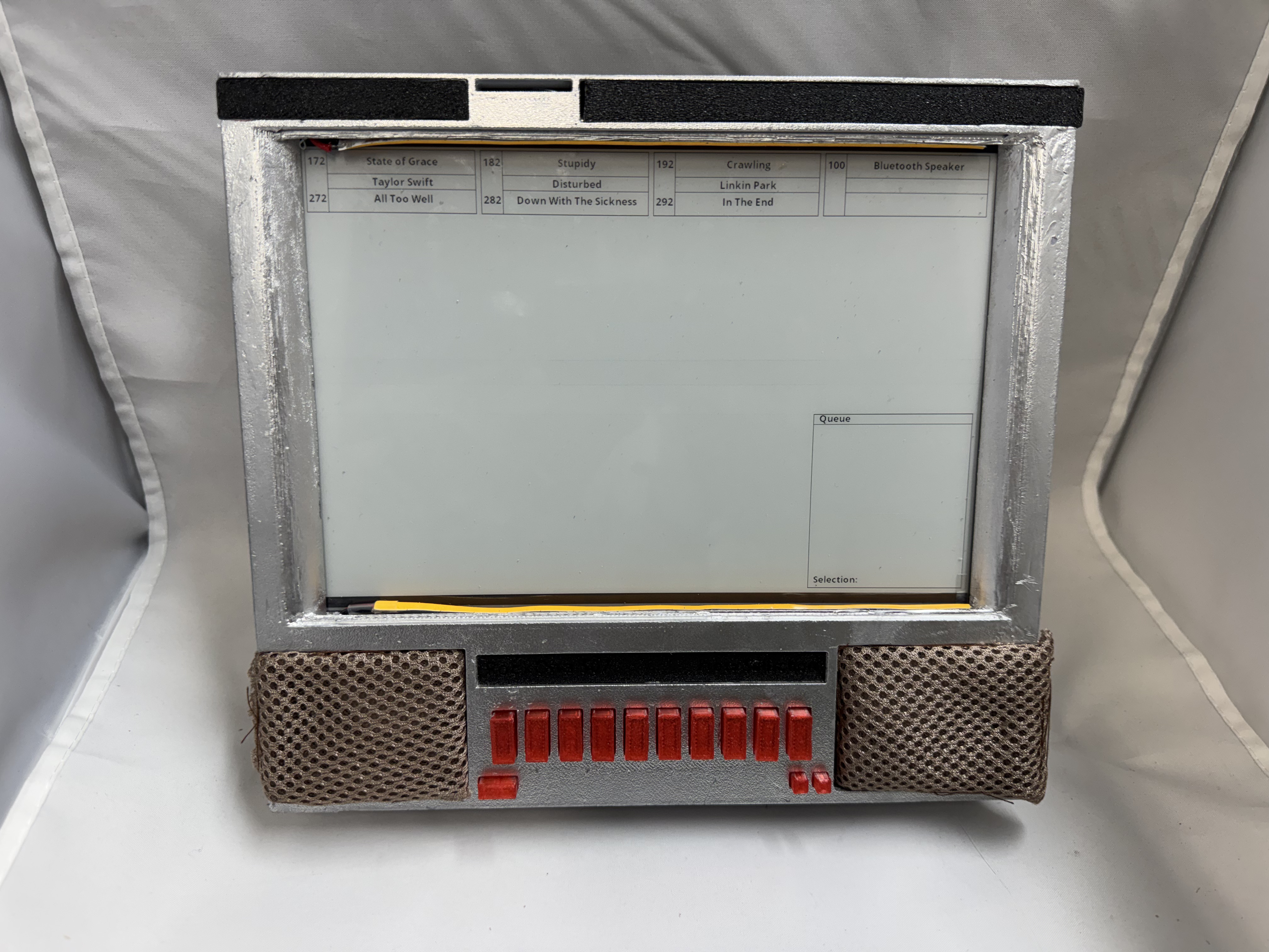
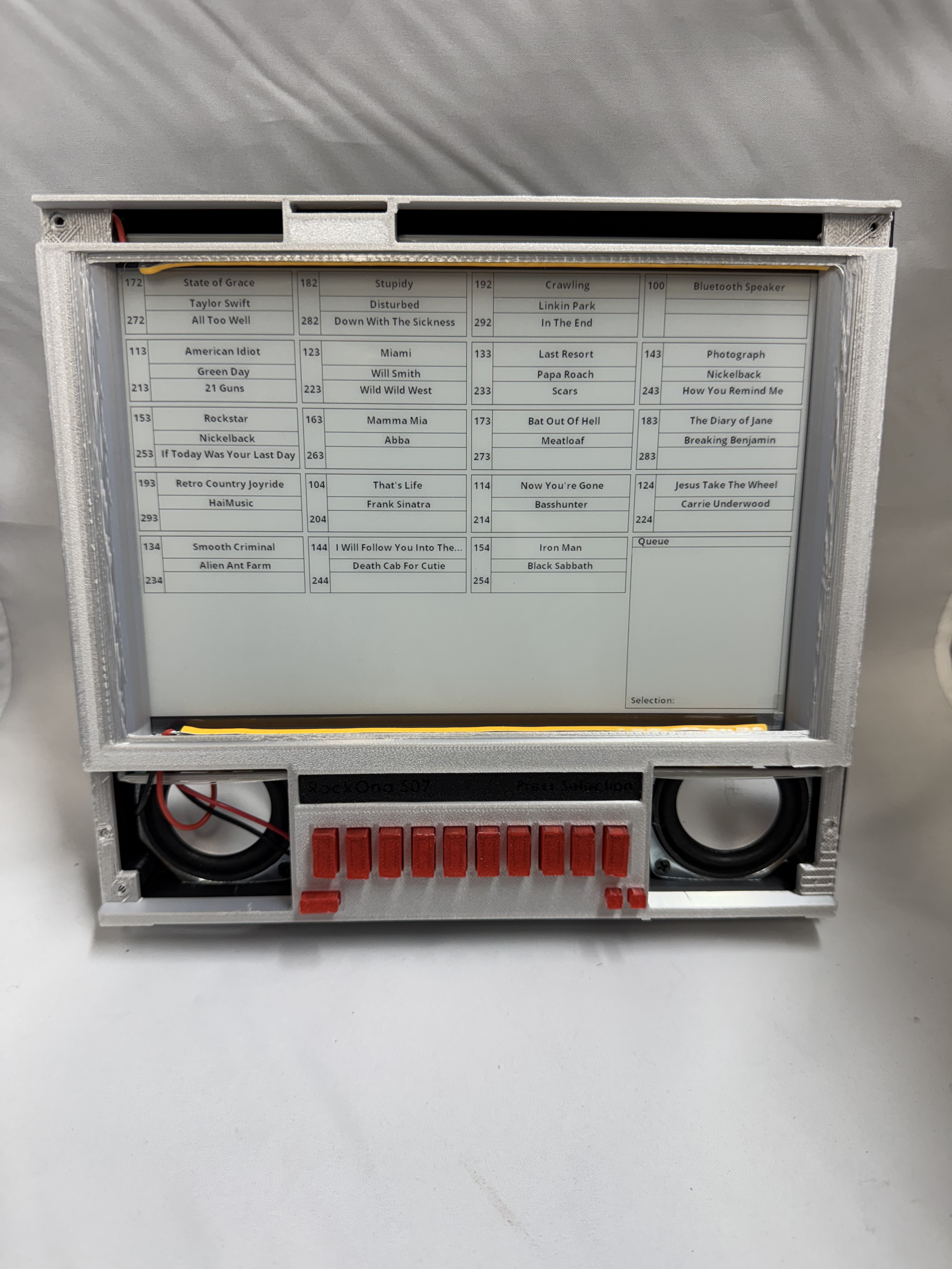
The idea is you could walk up to it, see a list of songs, and type in the numbers to queue it up. I could have my favorite songs available, and then also have a Bluetooth option for when you just want to stream from your phone.
(Photo from Rock-Ola 507 wallbox jukebox flyer | #102562020)
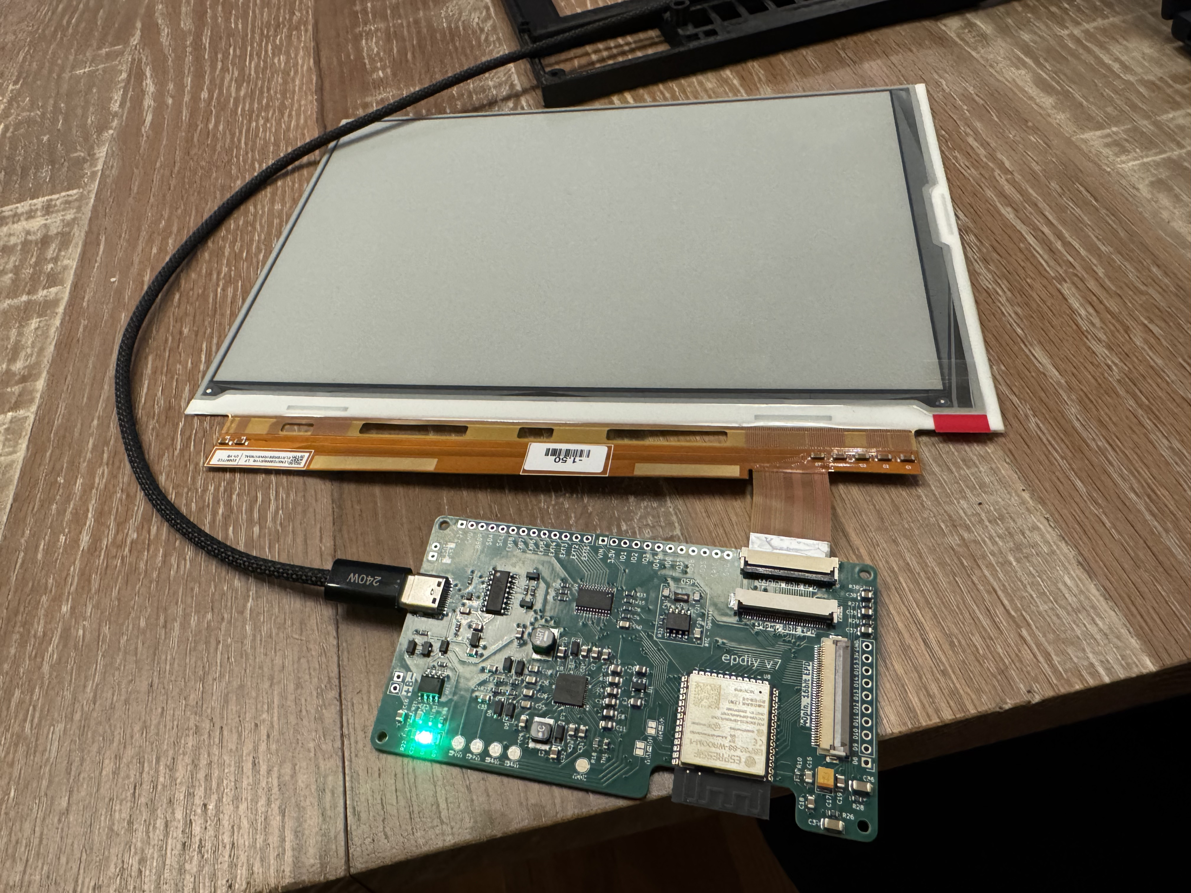
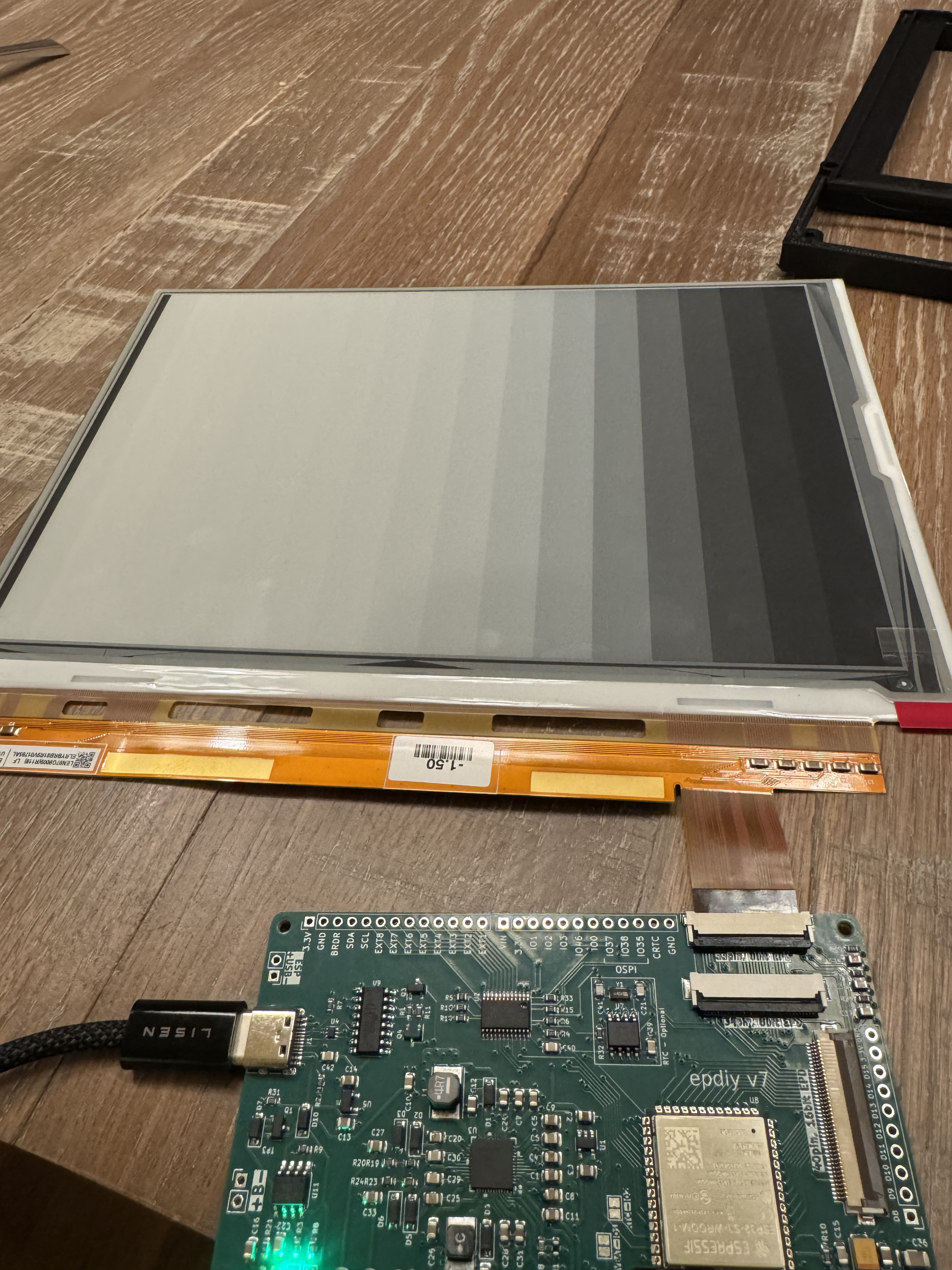
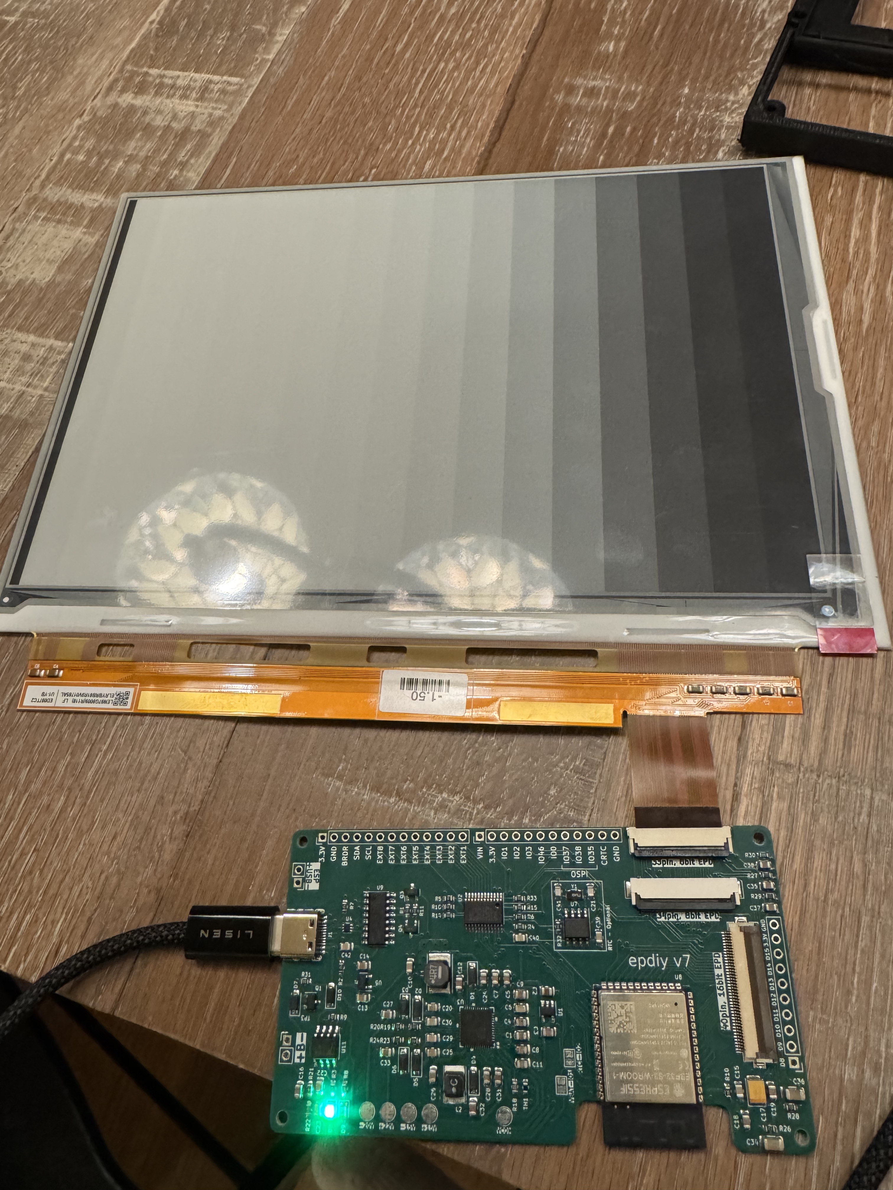
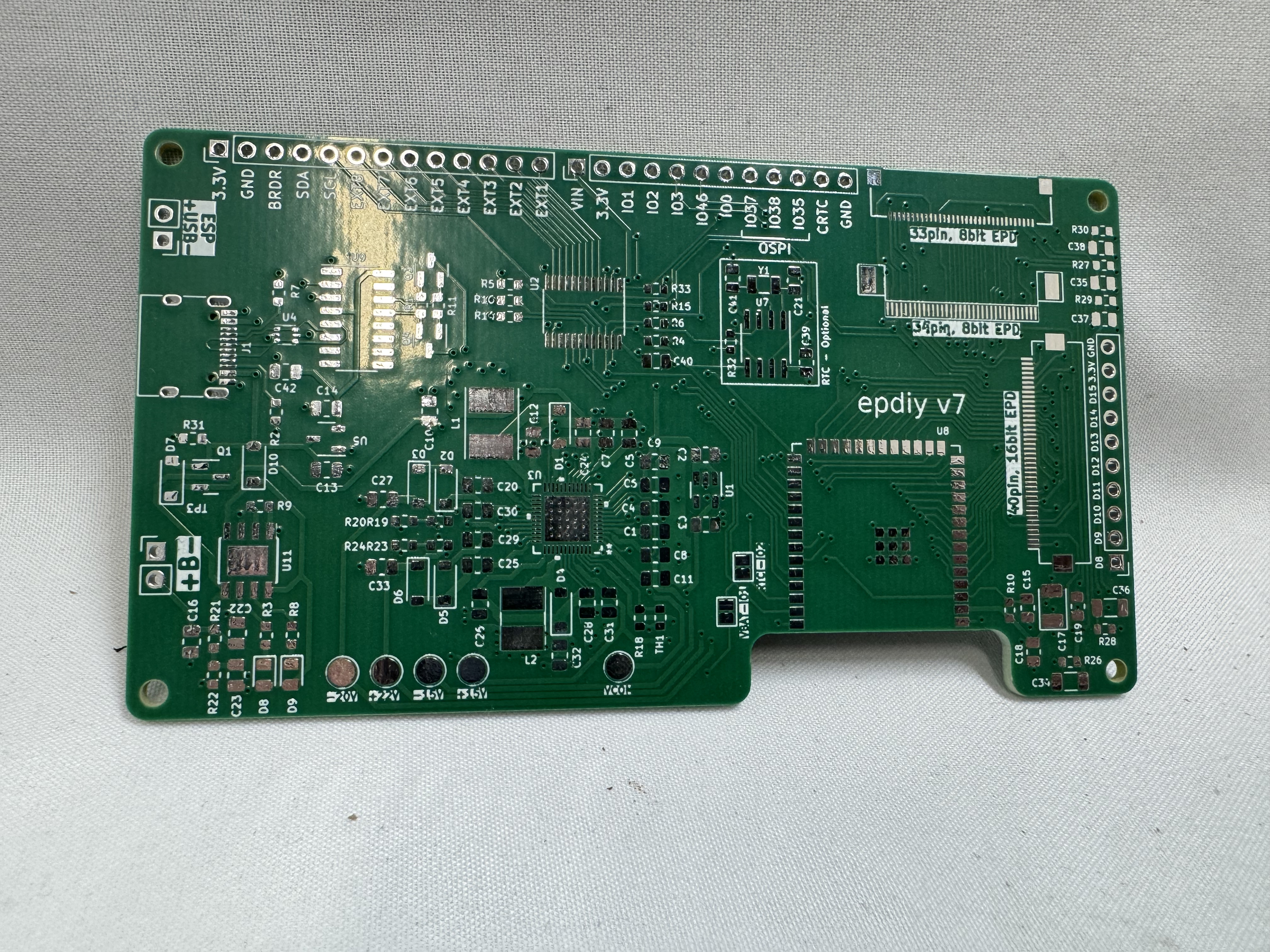
With this project I wanted to expand working with the ESP32 Audio board I did in the History Phone project. But also wanted a bit more of an old school vibe. To make the system feel more retro, one idea was to have the song list be an E-Ink screen. I thought that gave the system a softer feeling than an LCD screen. I have not used E-Ink in a project before; it turns out E-Ink panels need a special driver board. E-Ink is also not cheap, a 9.7″ panel will be $70, then you need the driver board. There are not standard boards out there to do what I wanted to, then I found an awesome open-source project!
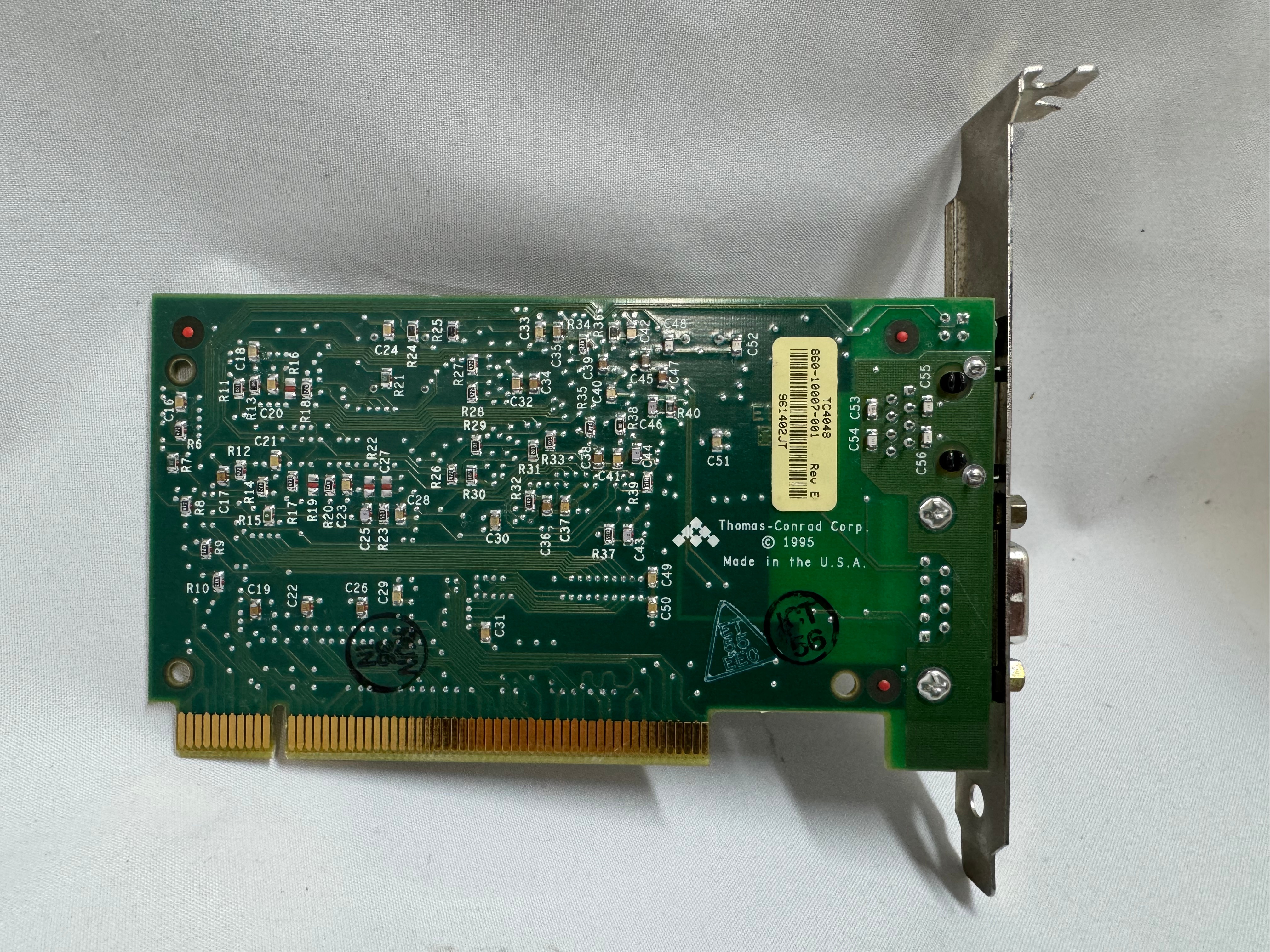
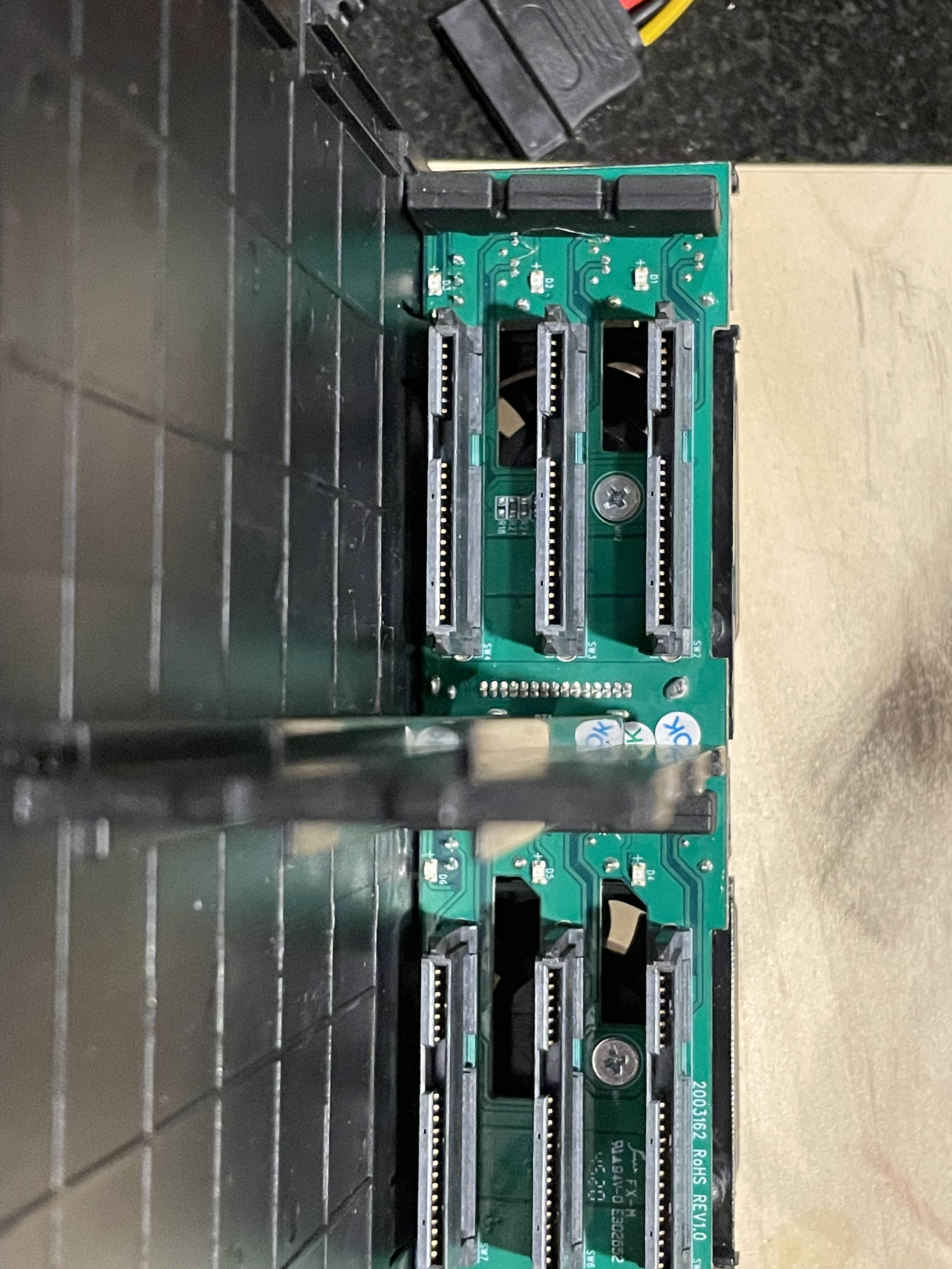
Circuit Board Ordering with PCBWay
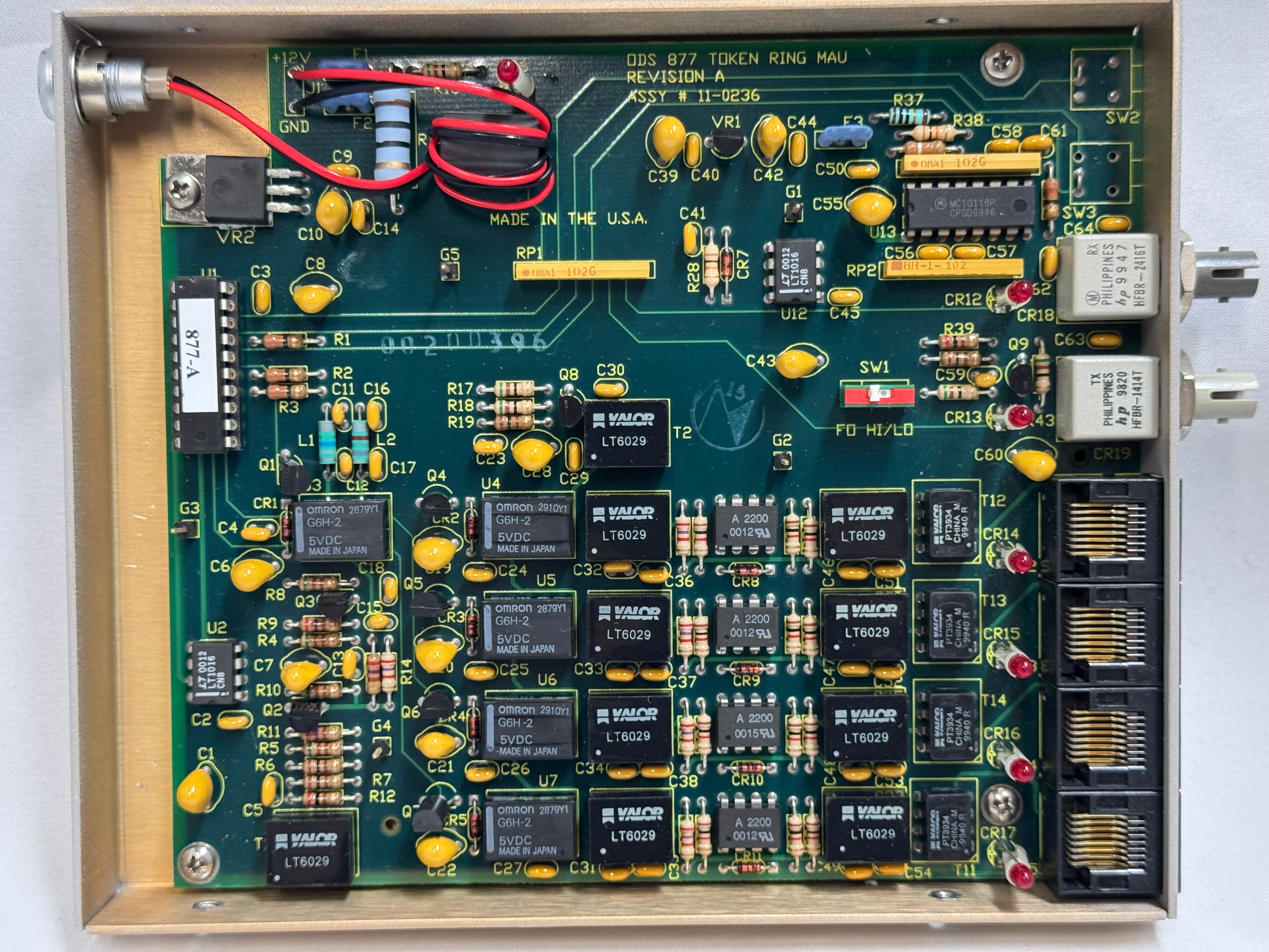
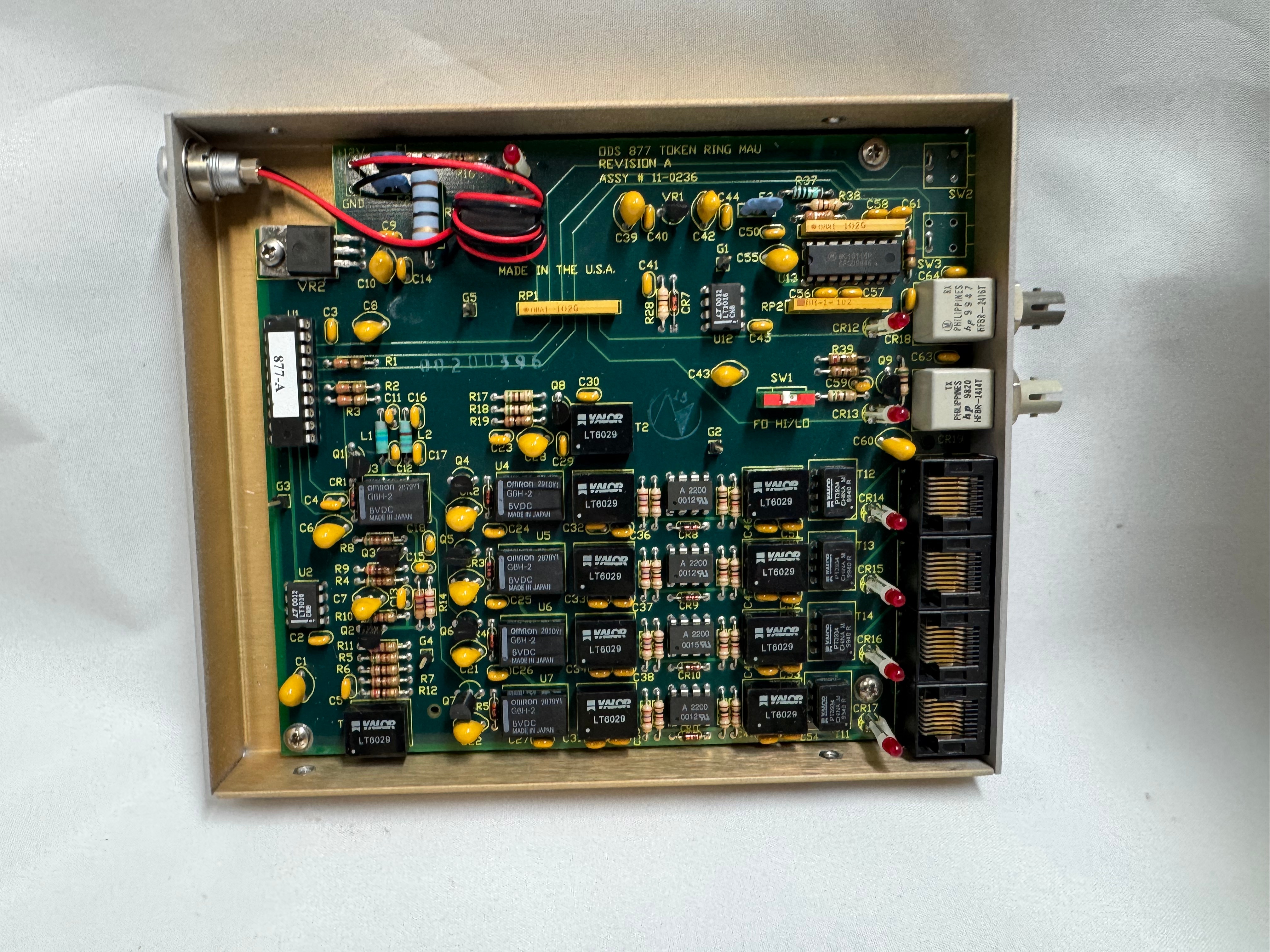
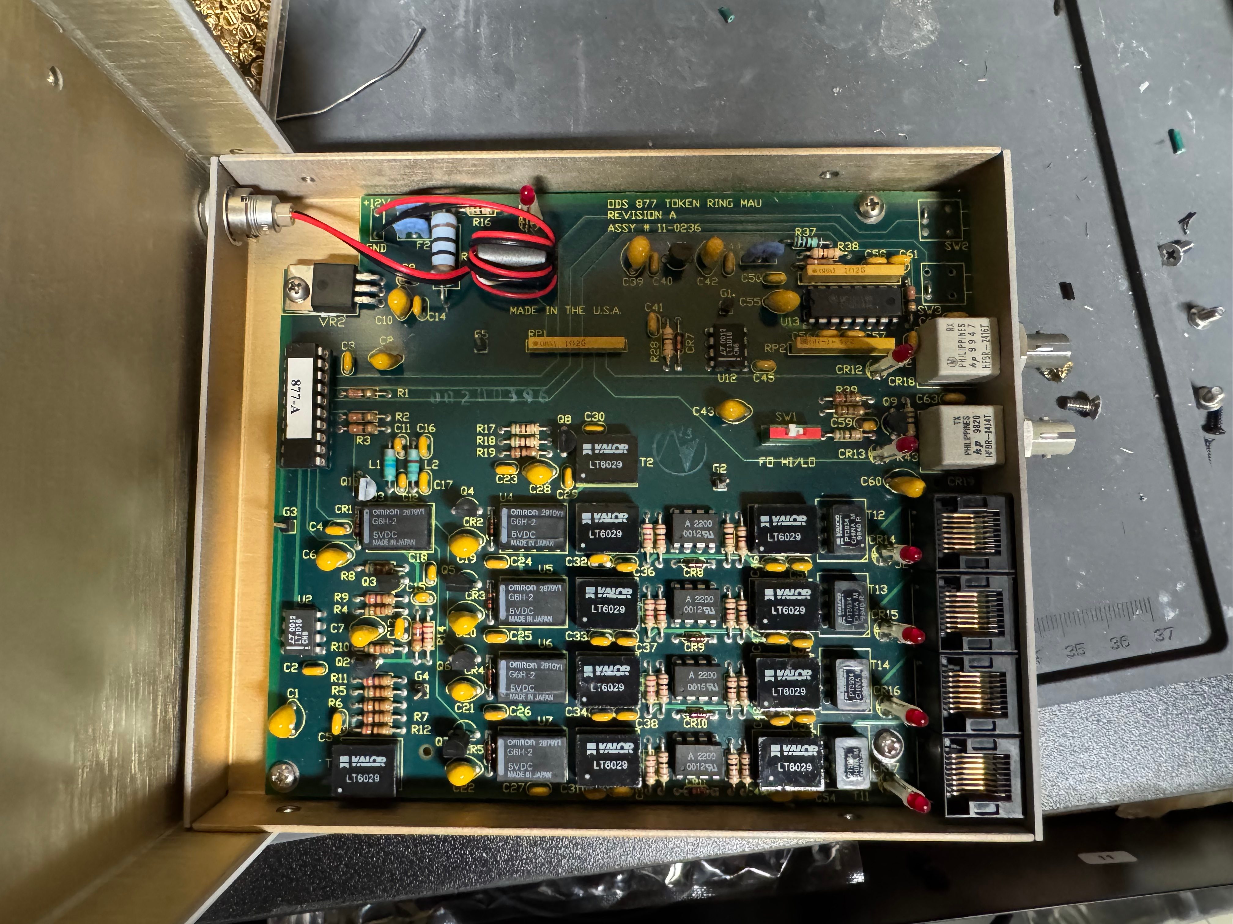
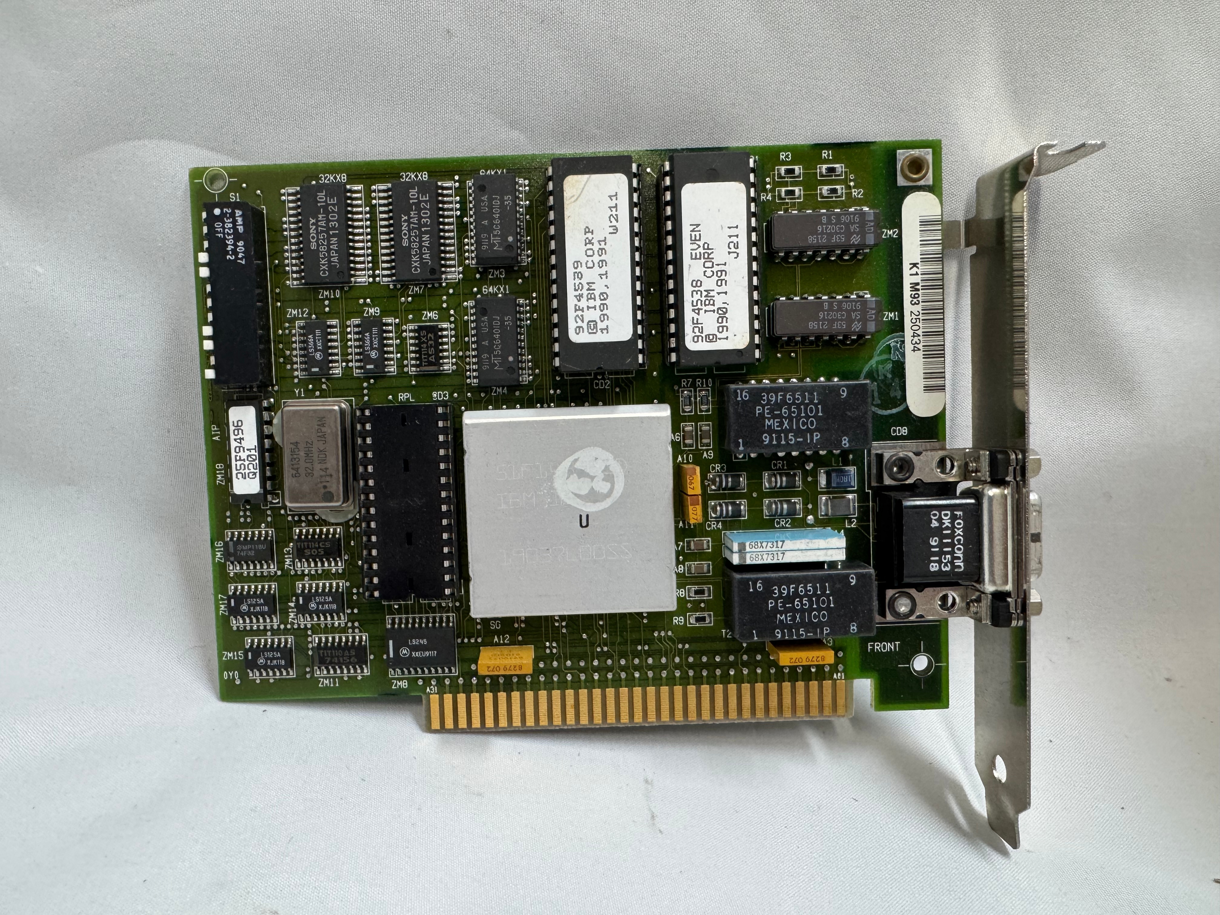
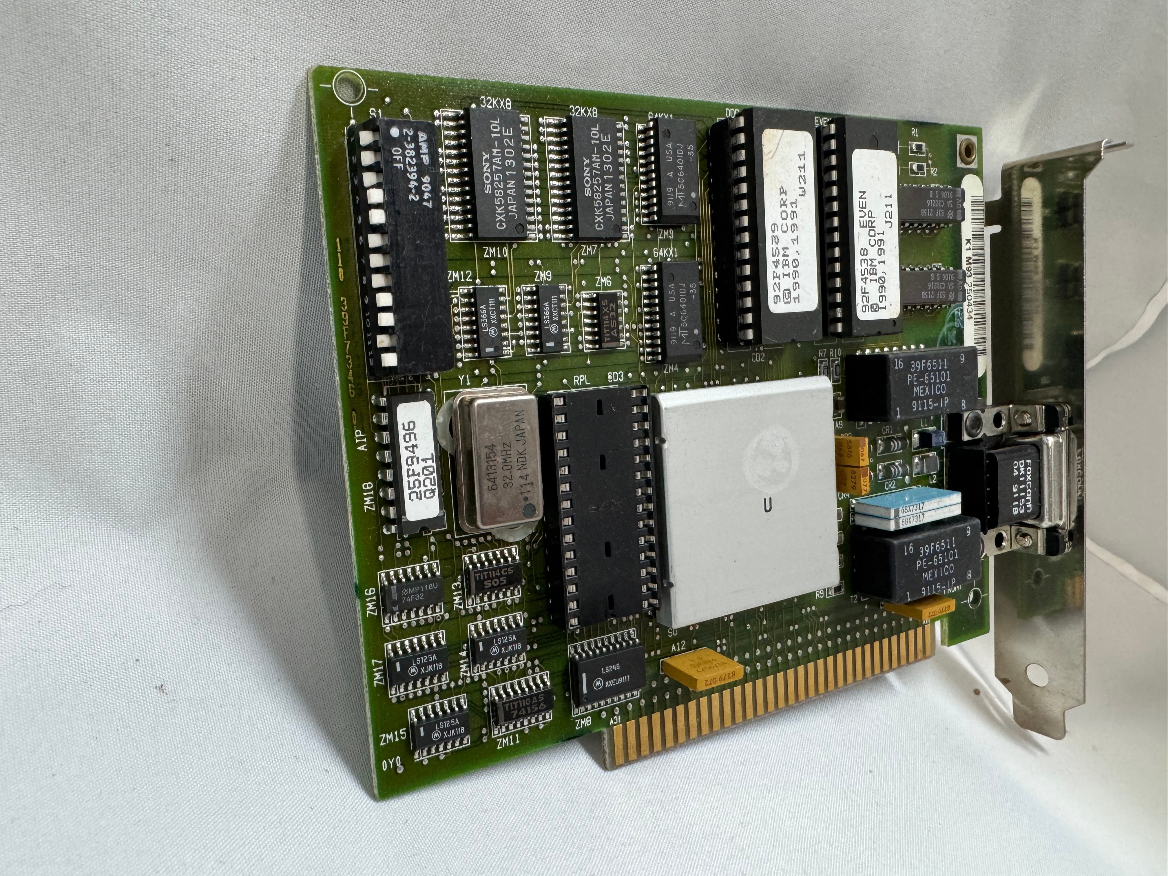
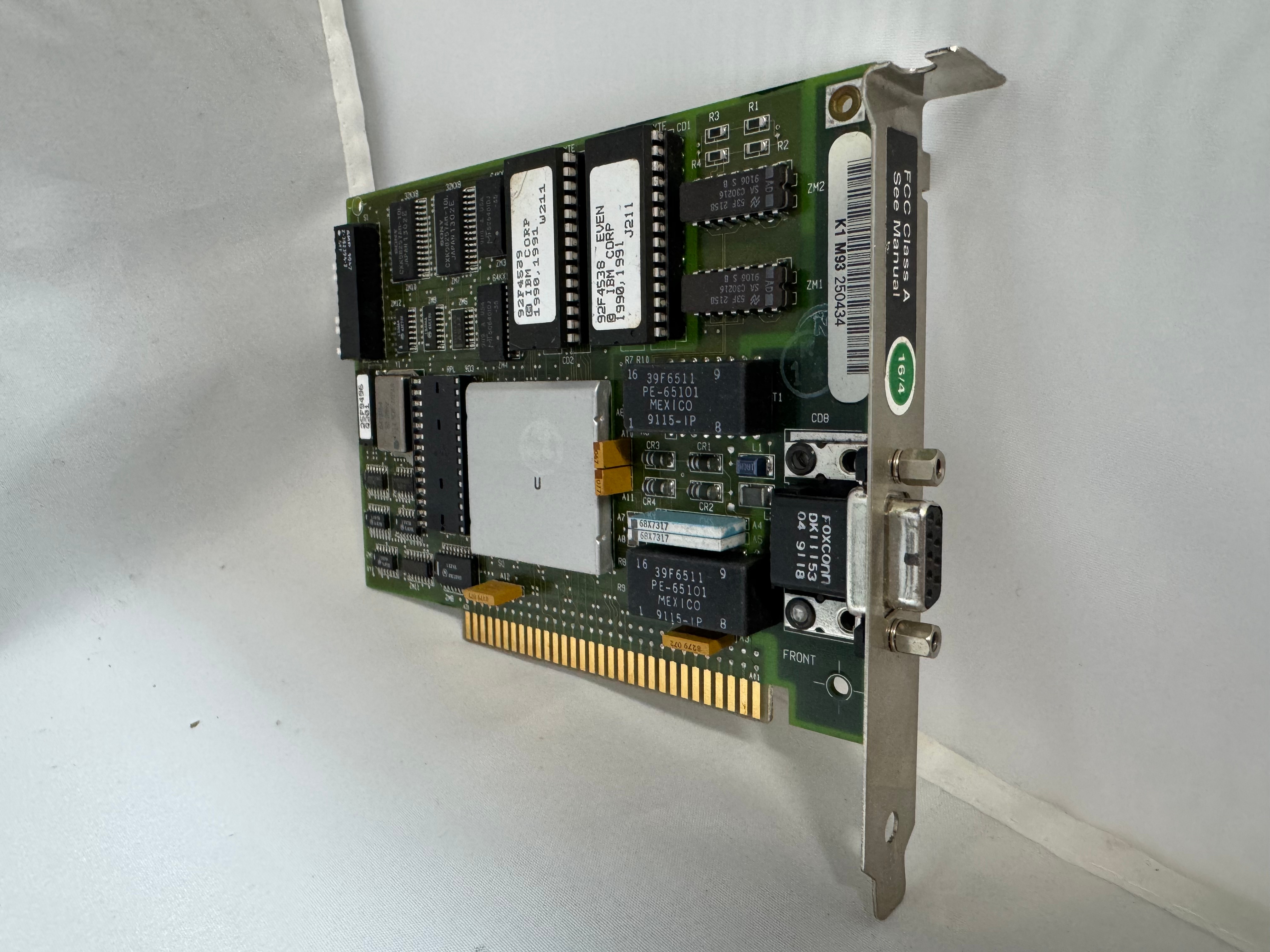
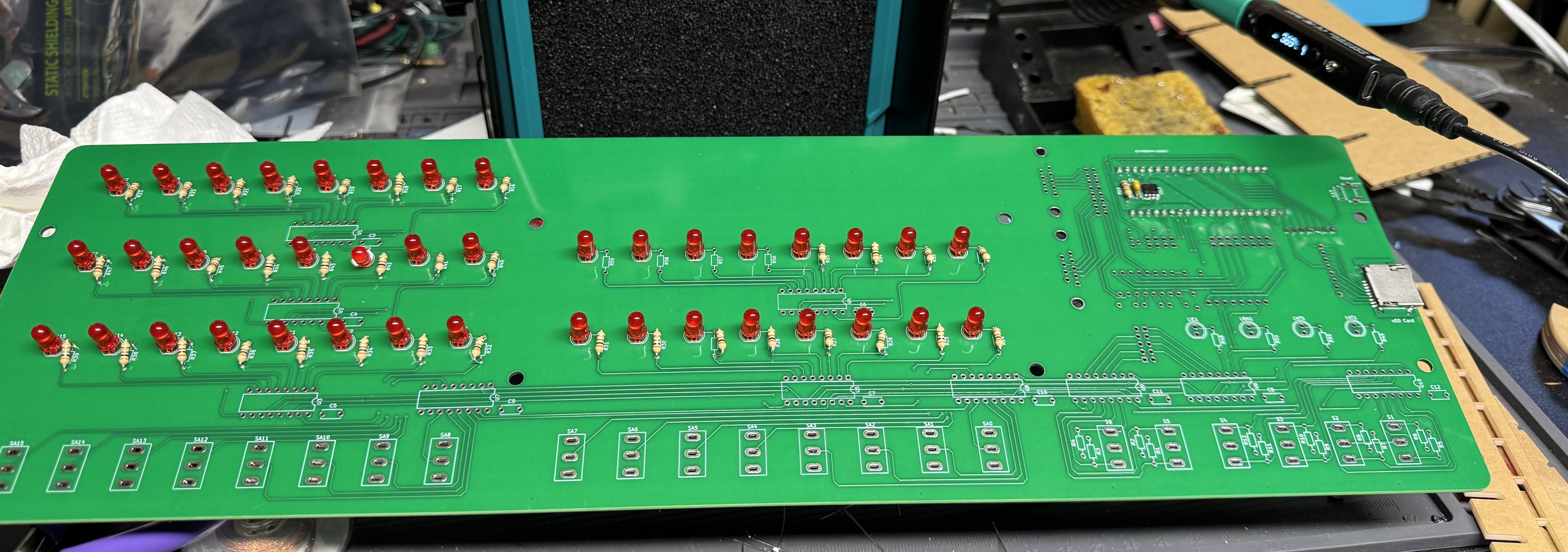
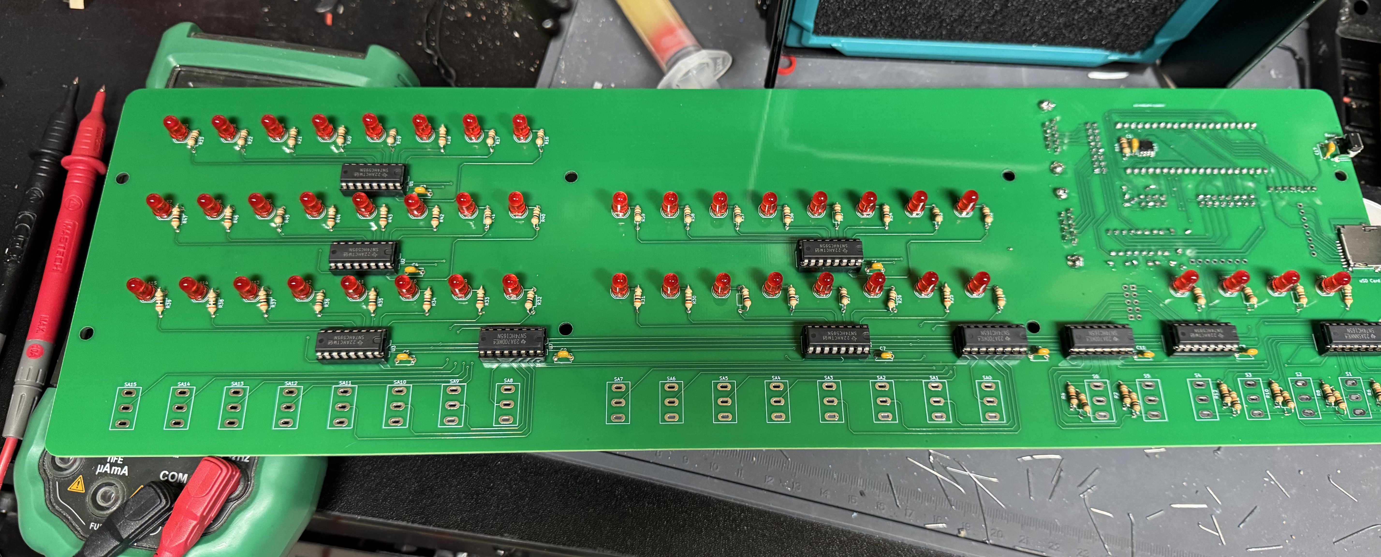
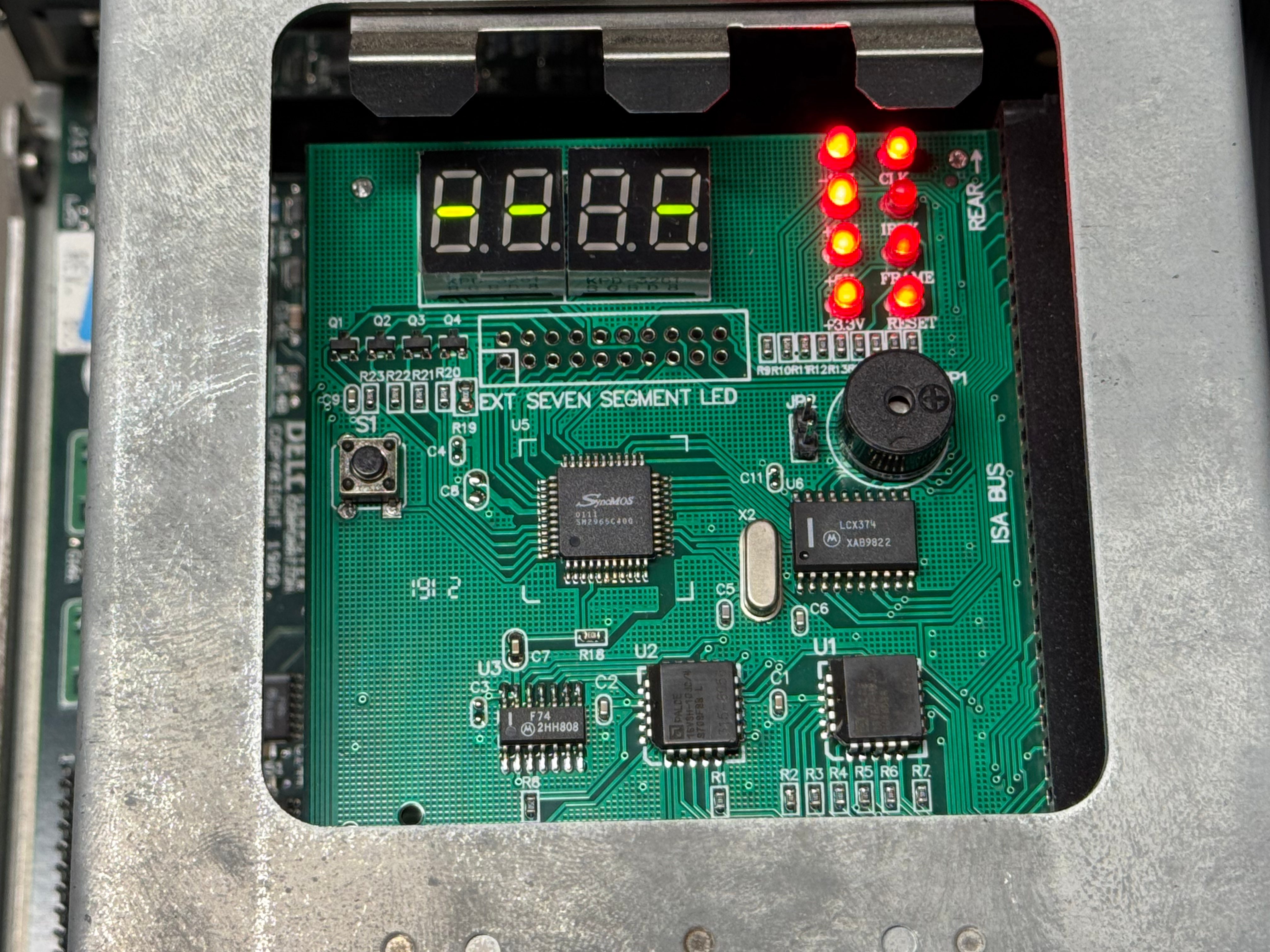
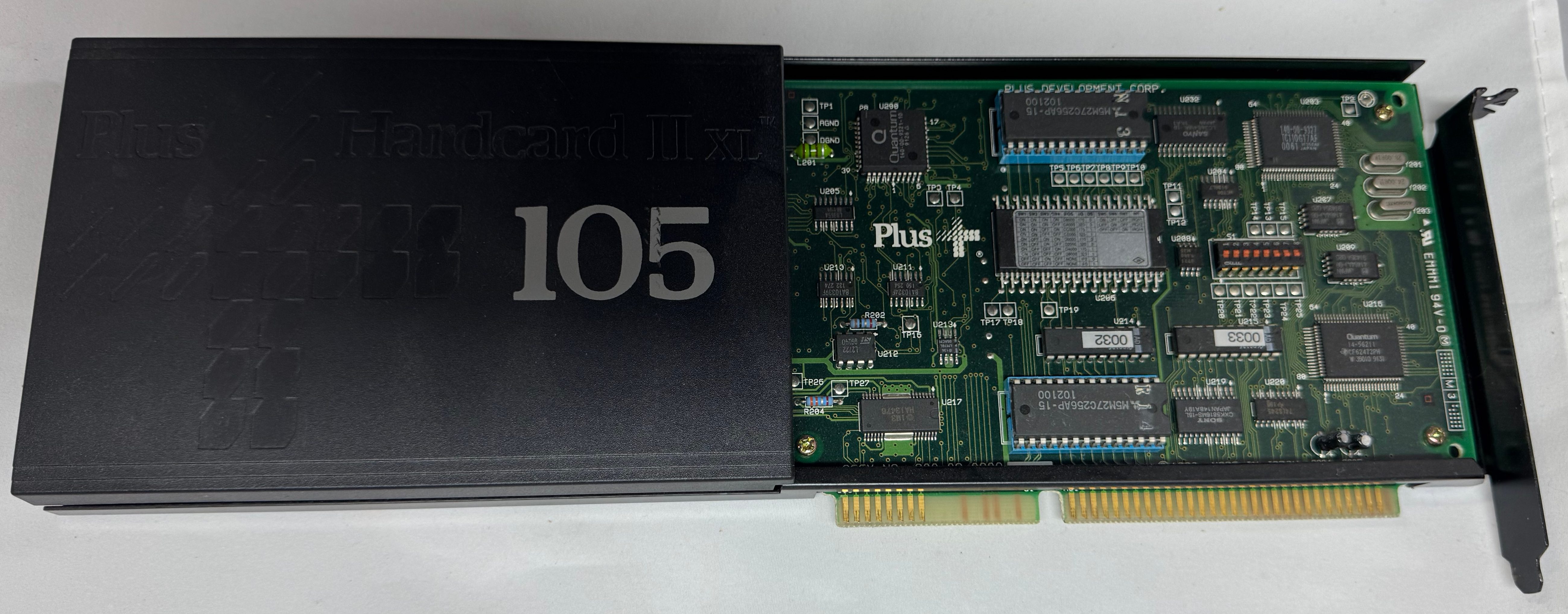
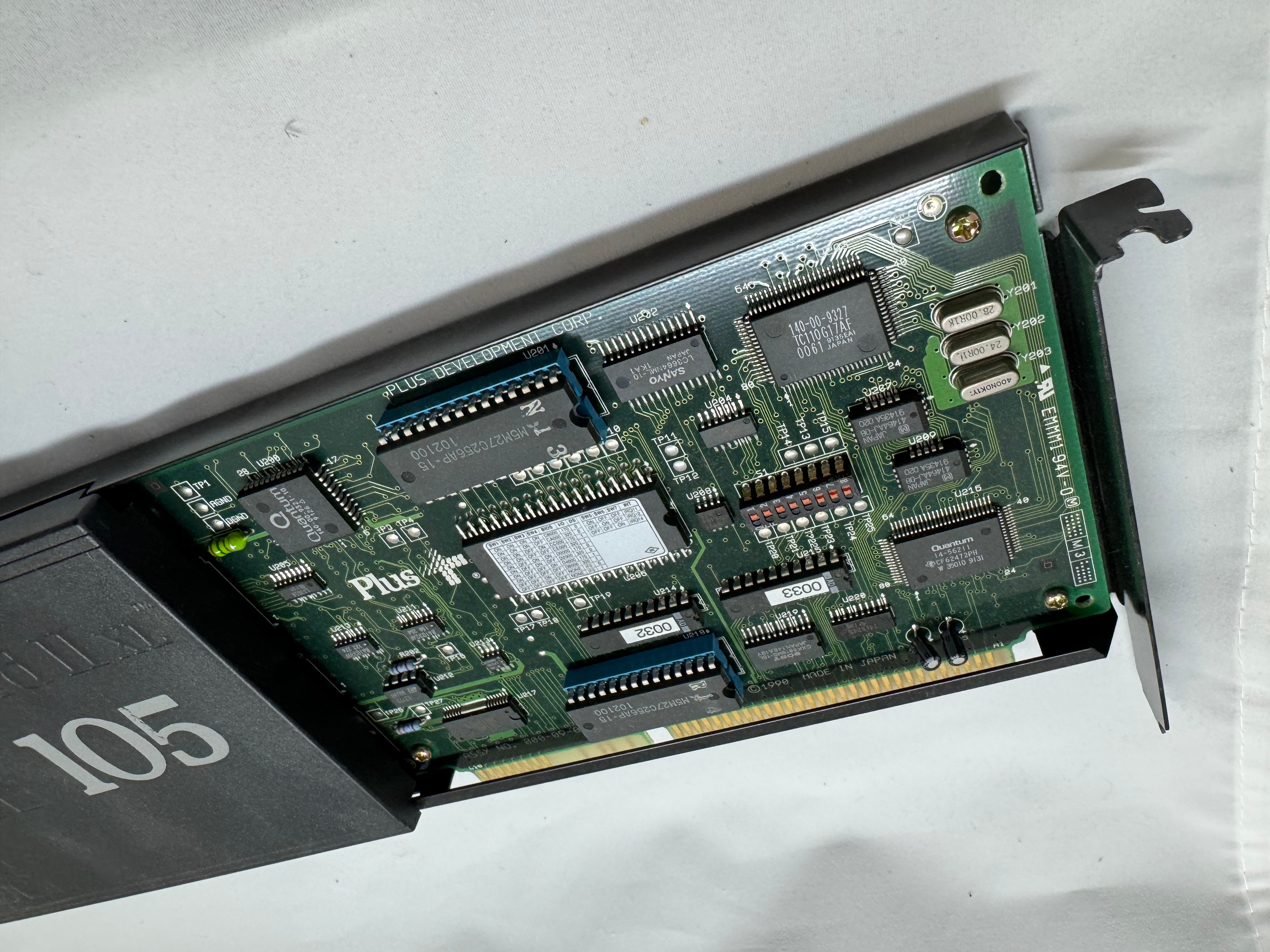
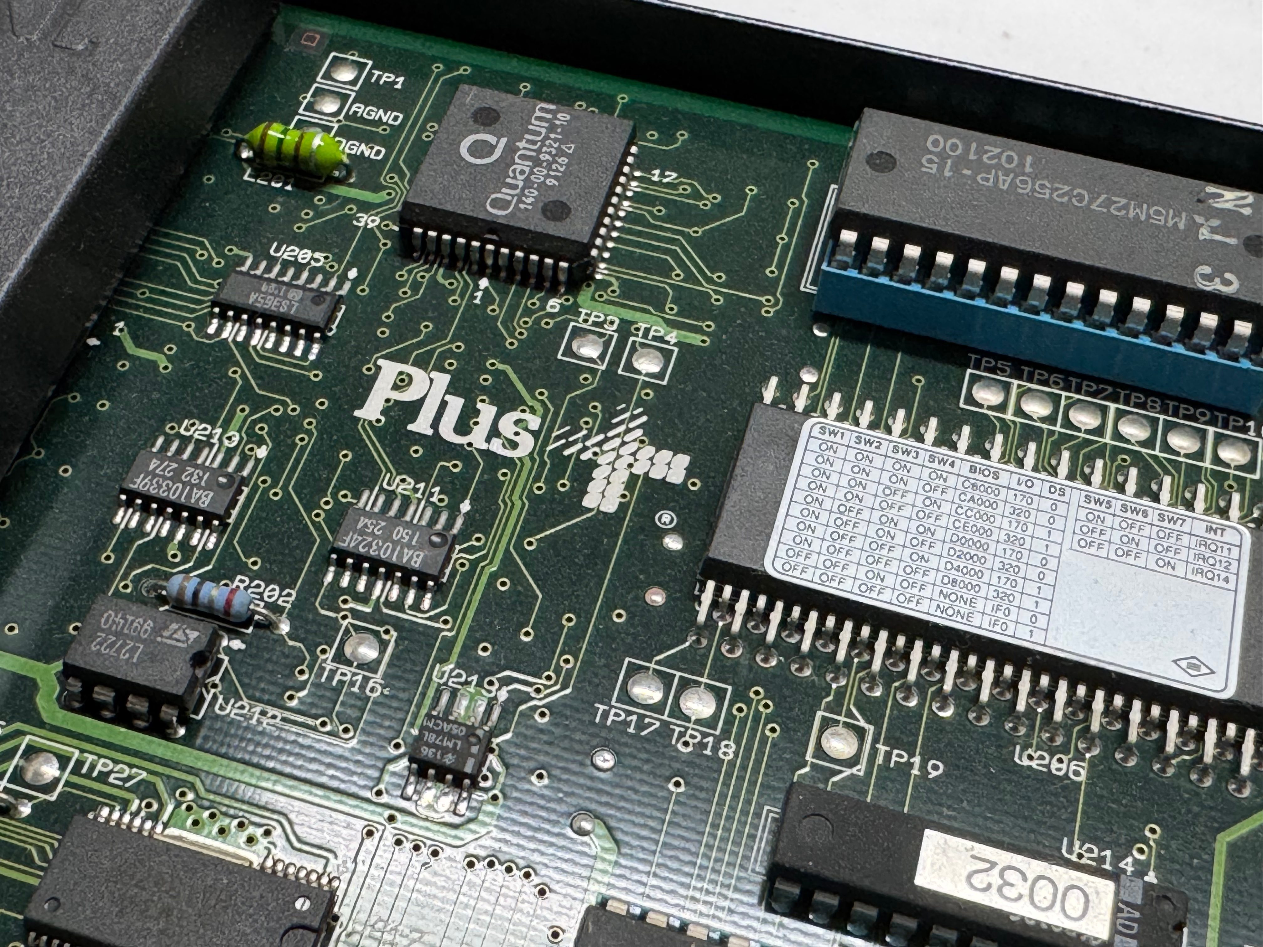
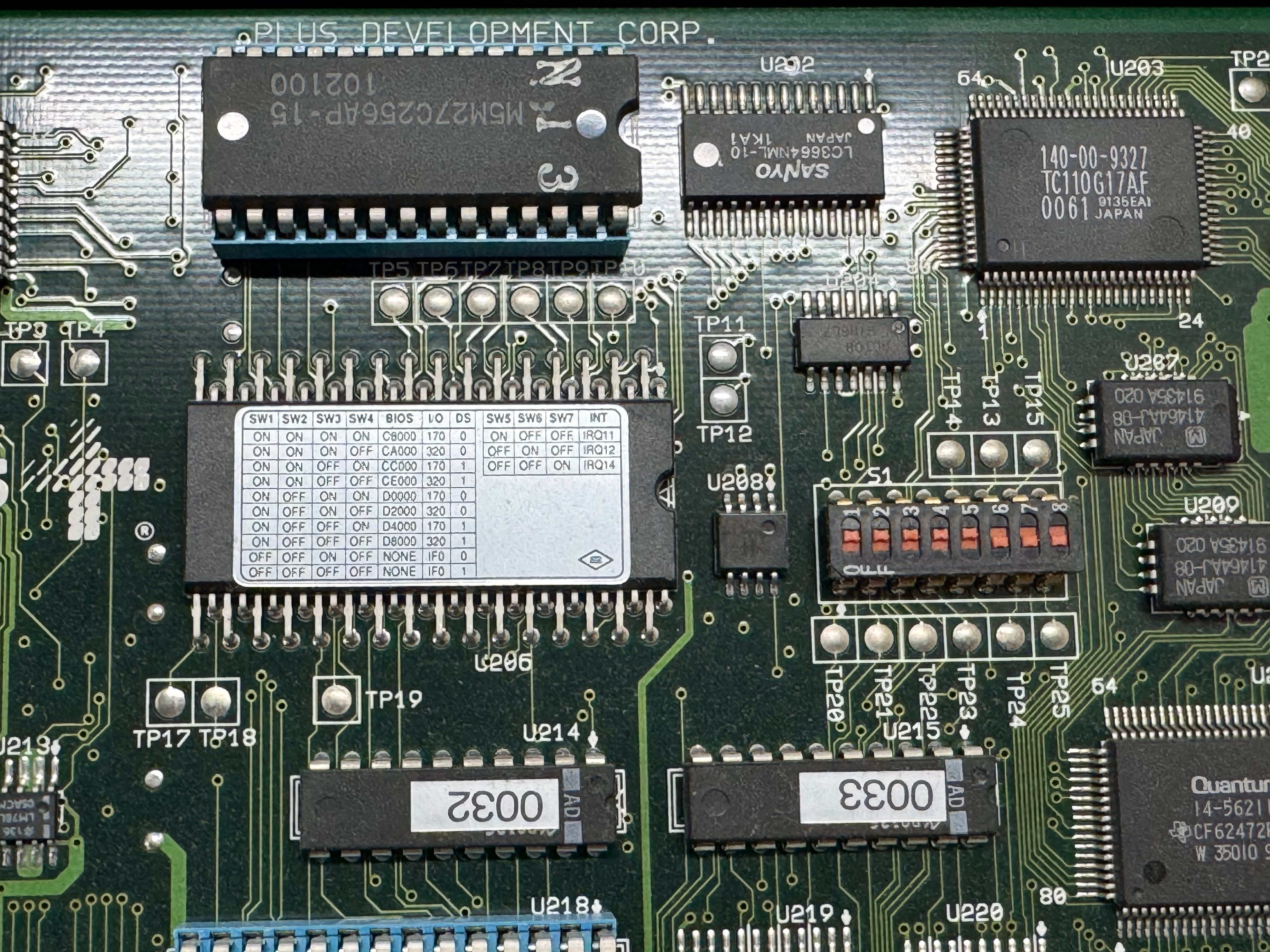
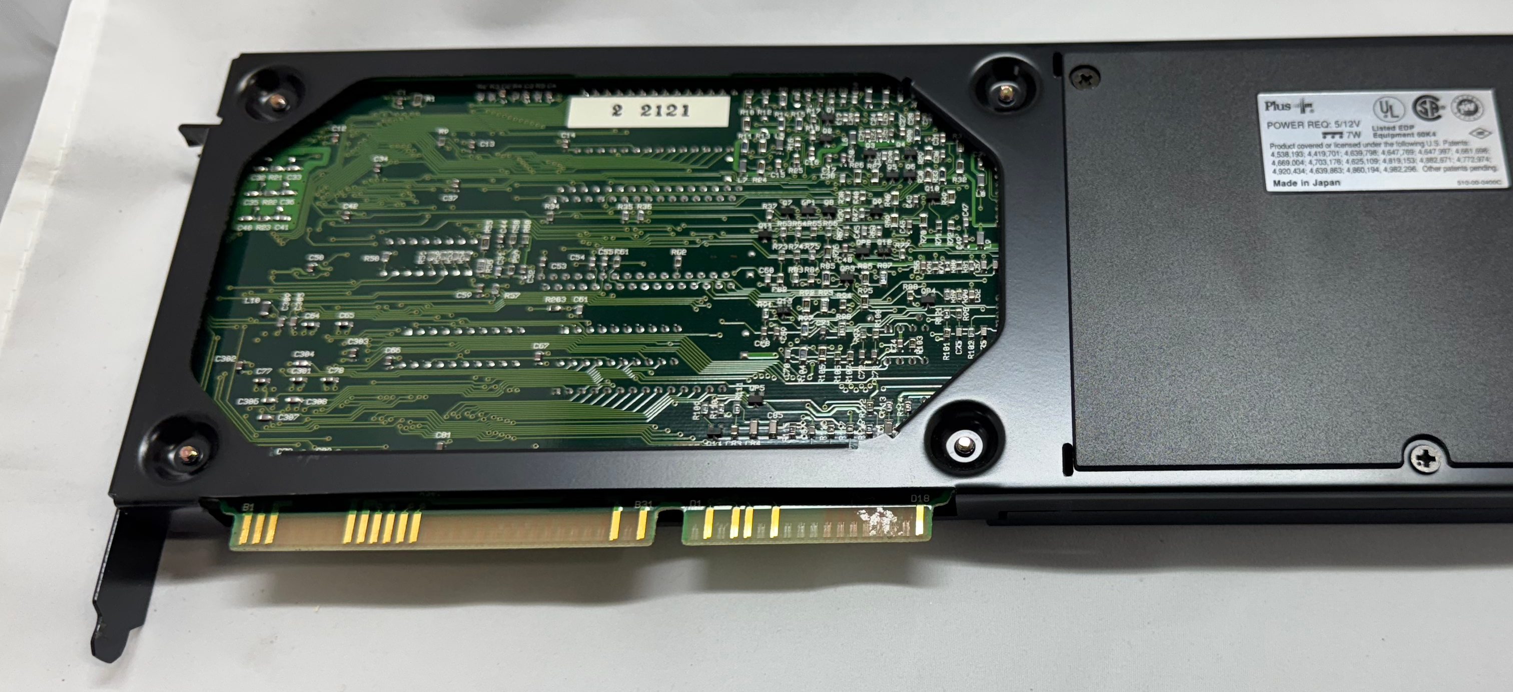
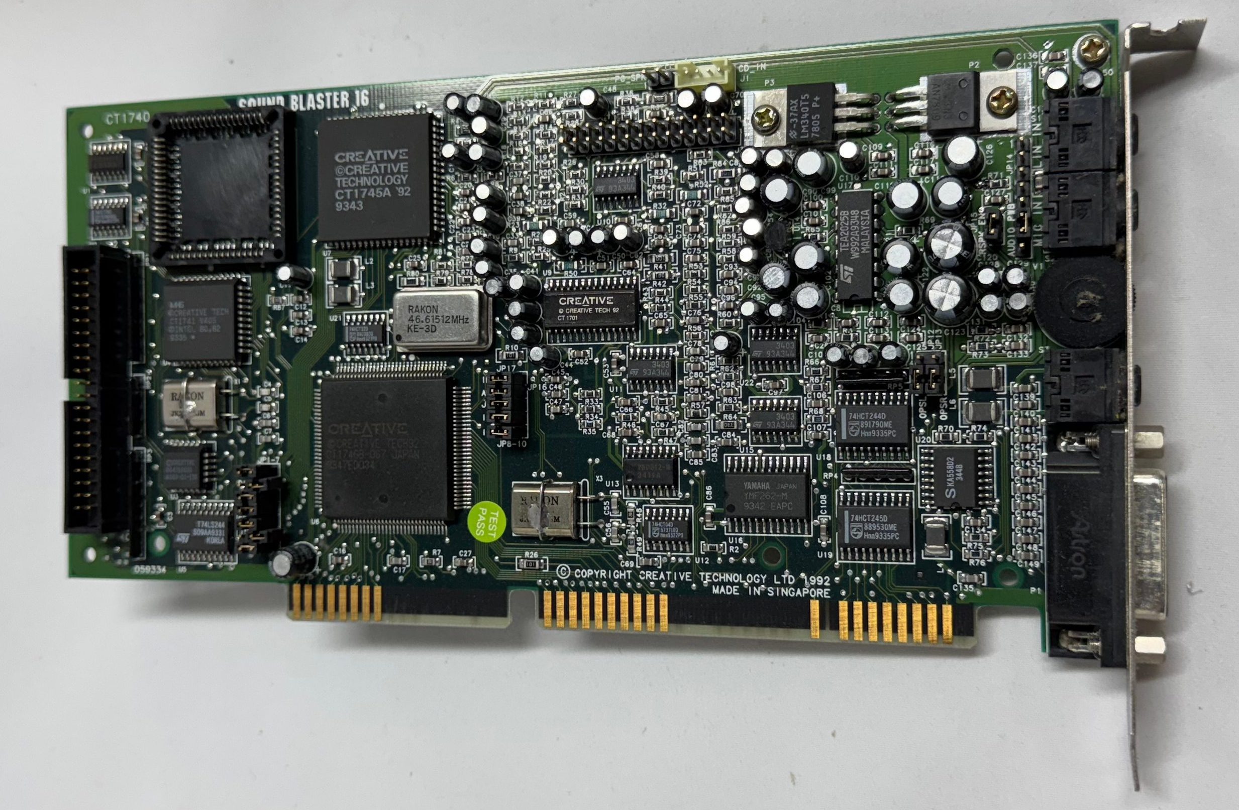
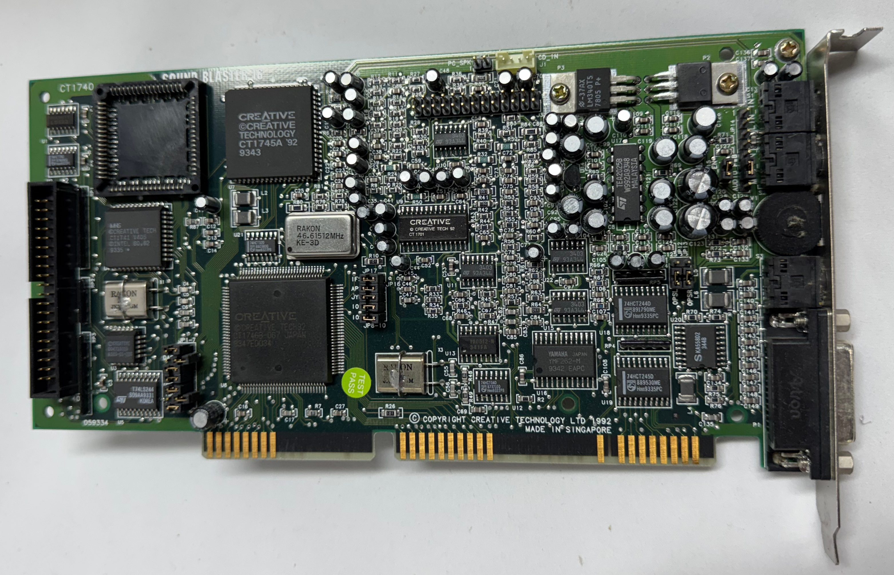
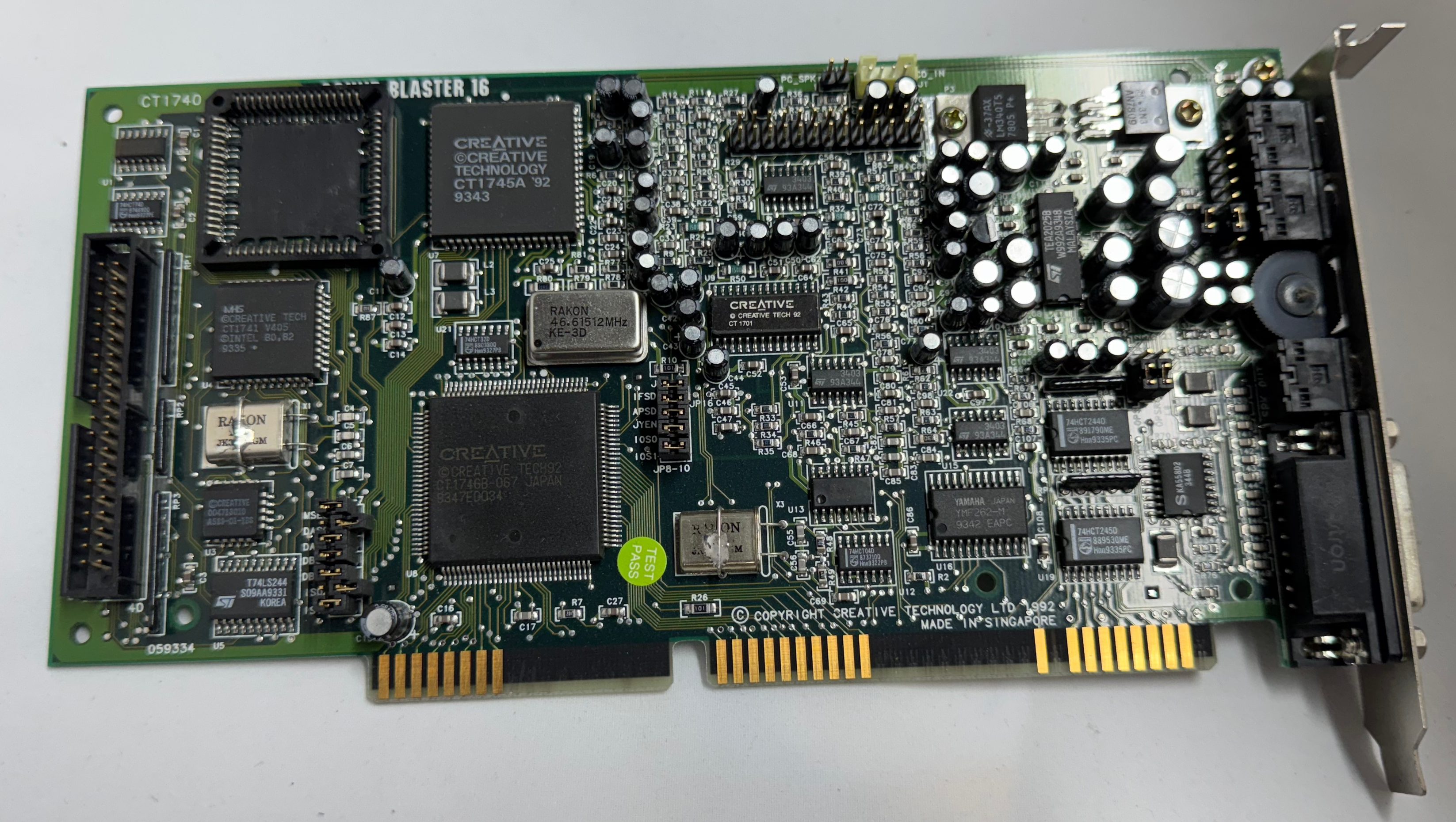
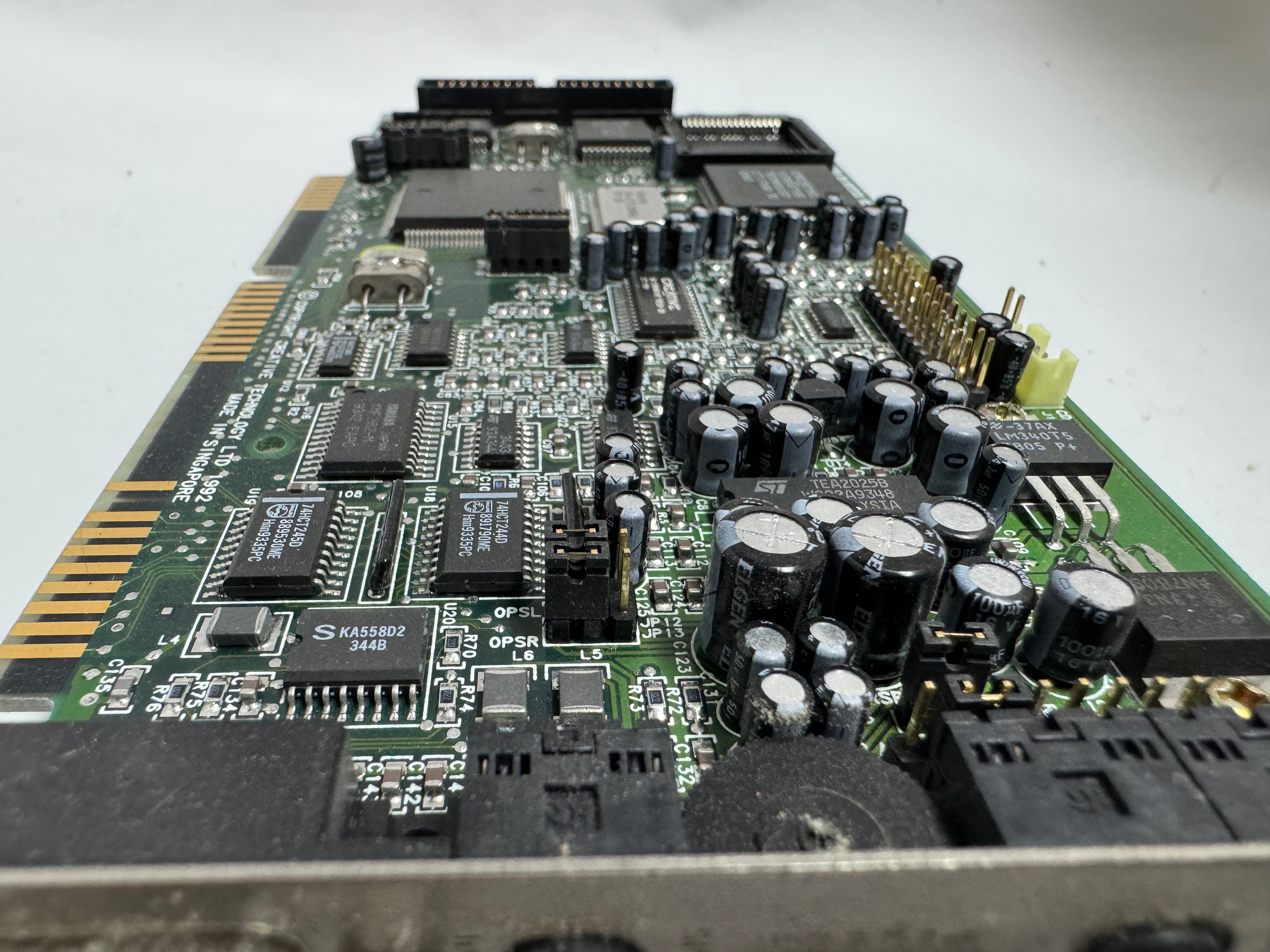
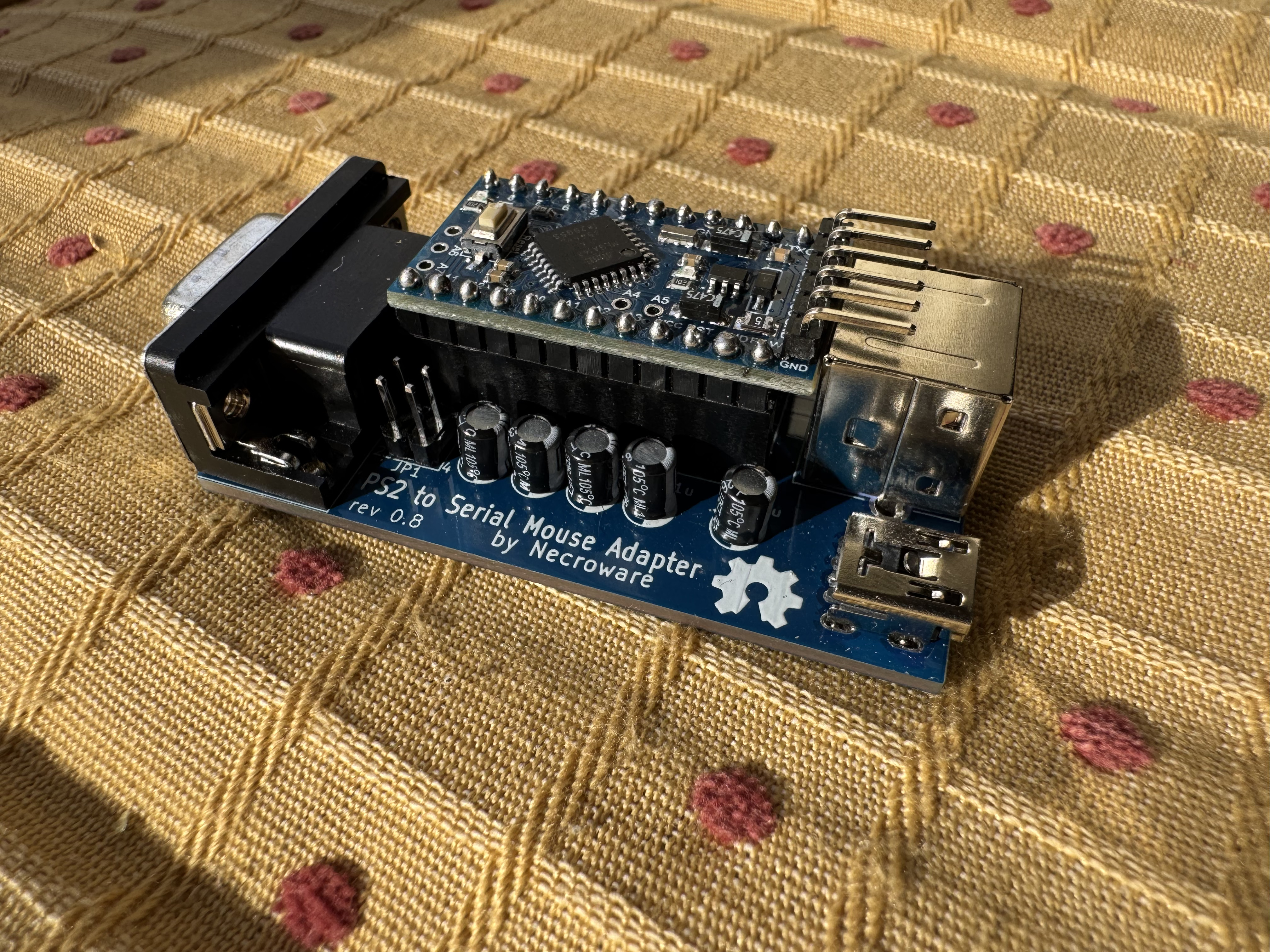
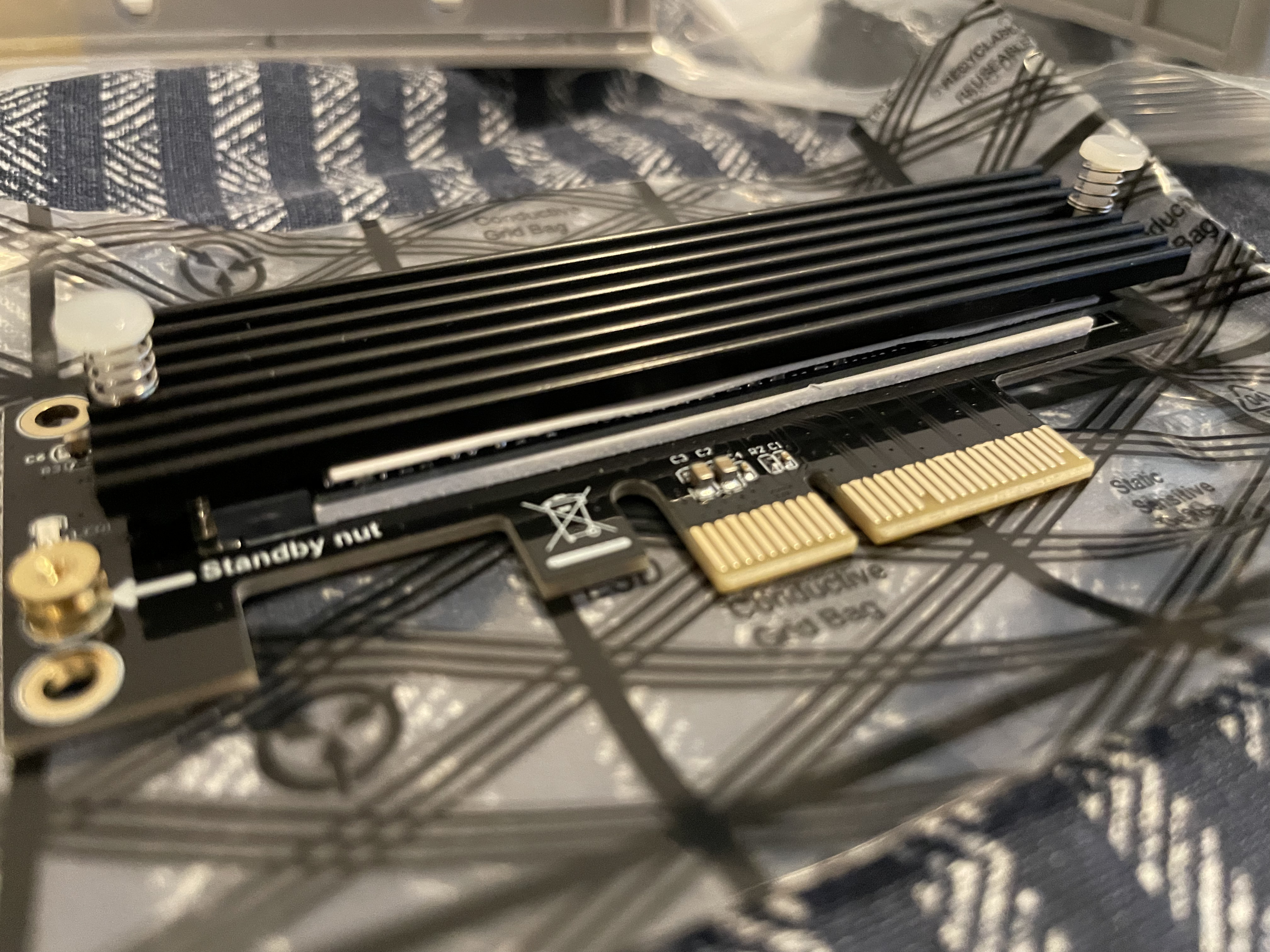
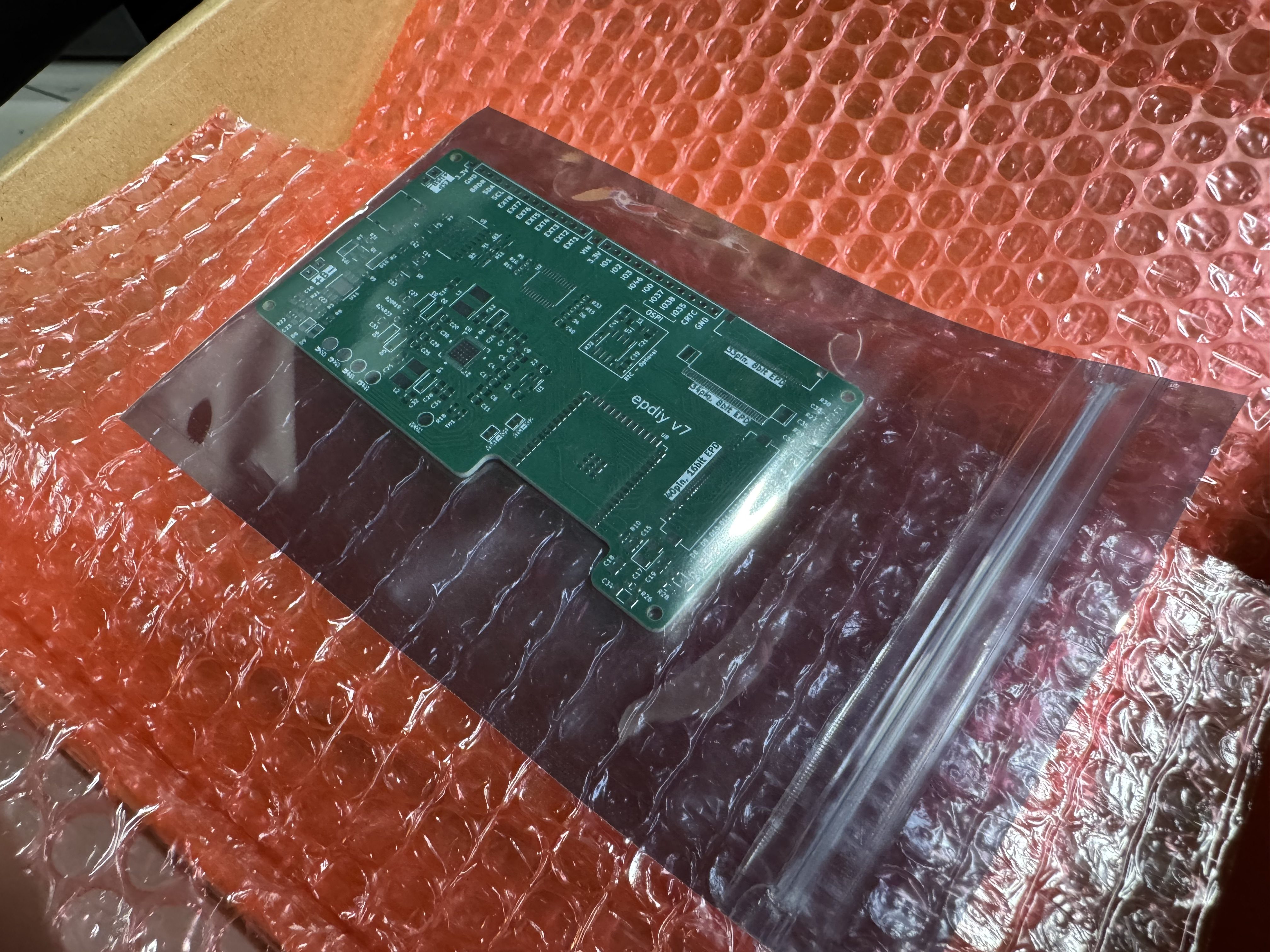
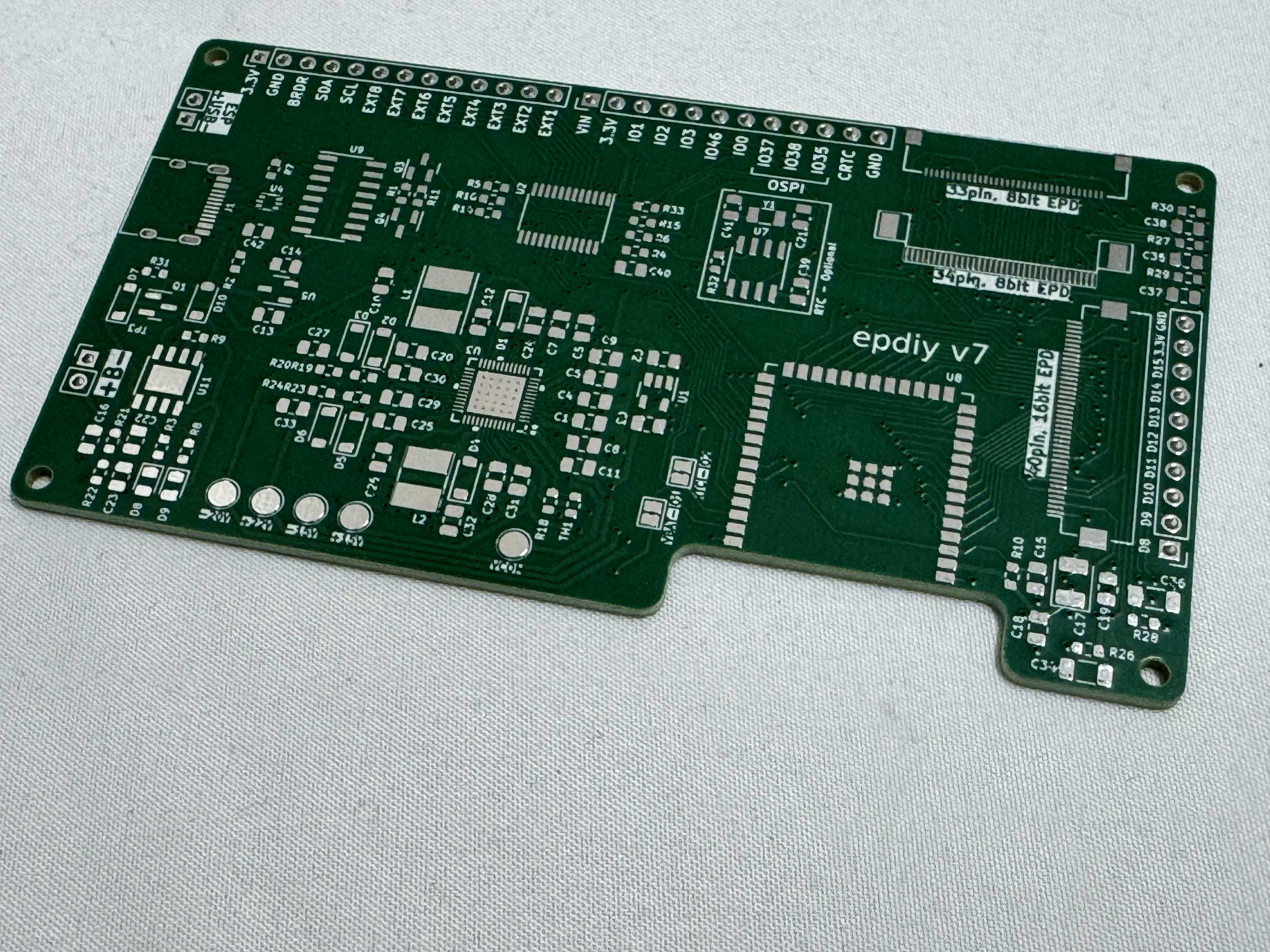
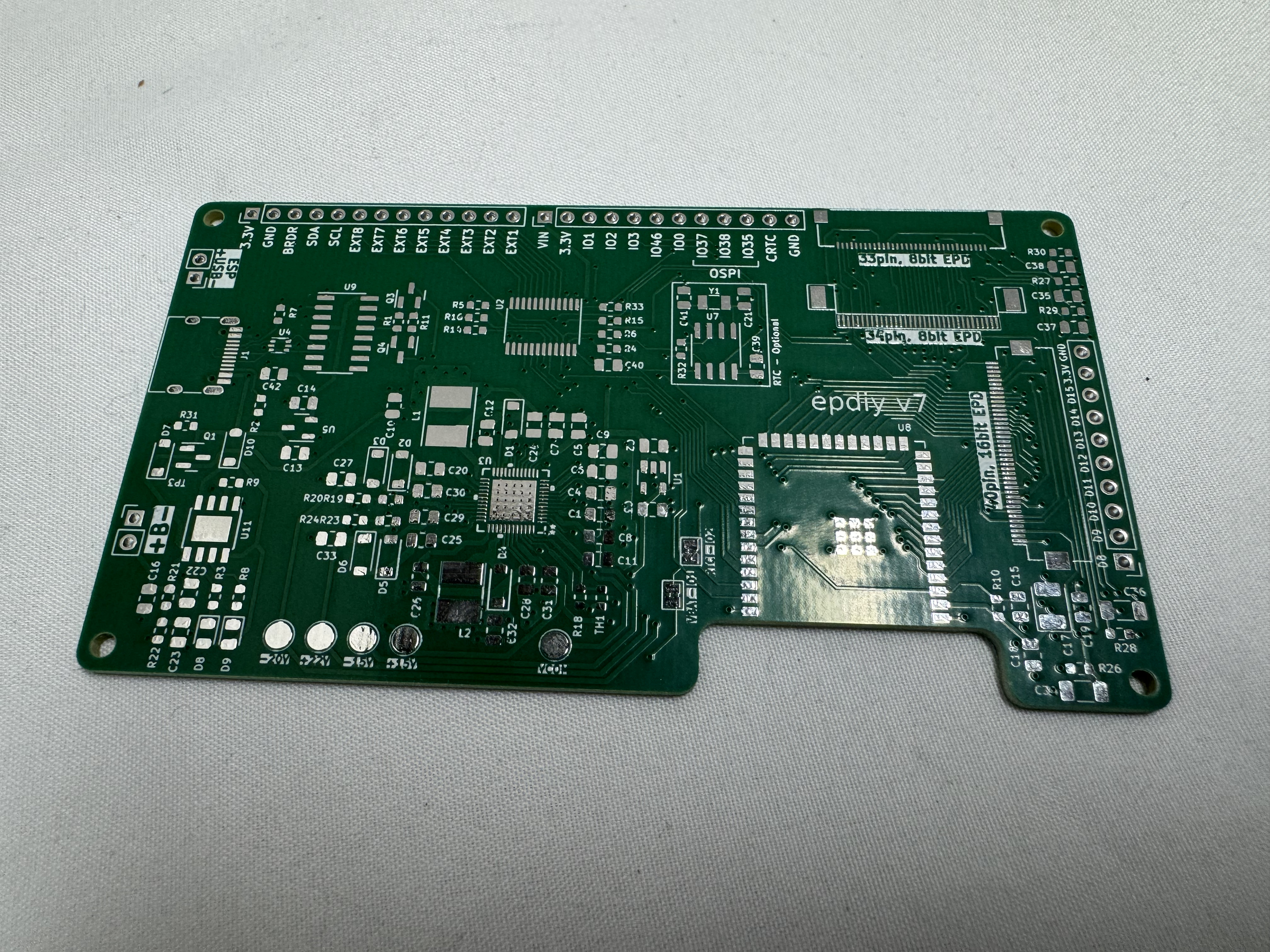
EPDiy (e-paper diy) is an open-source project on its 7th version of a universal E-Ink driver board! This introduced a new challenge for me; how do I get the boards made. I have not made circuit boards before, and while I have thought about making boards before, it seemed like an uphill battle. I had heard about PCBWay from Youtube videos and podcasts. I knew they had a shared projects area and hoped someone had done the heavy lifting here. Turns out someone had already uploaded the design and had it ready to go! I was not ready to push forward with the project yet and shelved the project for a bit. A few weeks later, PCBWay reached out after seeing the blog and asked if they could help pay for some of the boards to be made if I spoke about the process. It was a great match!
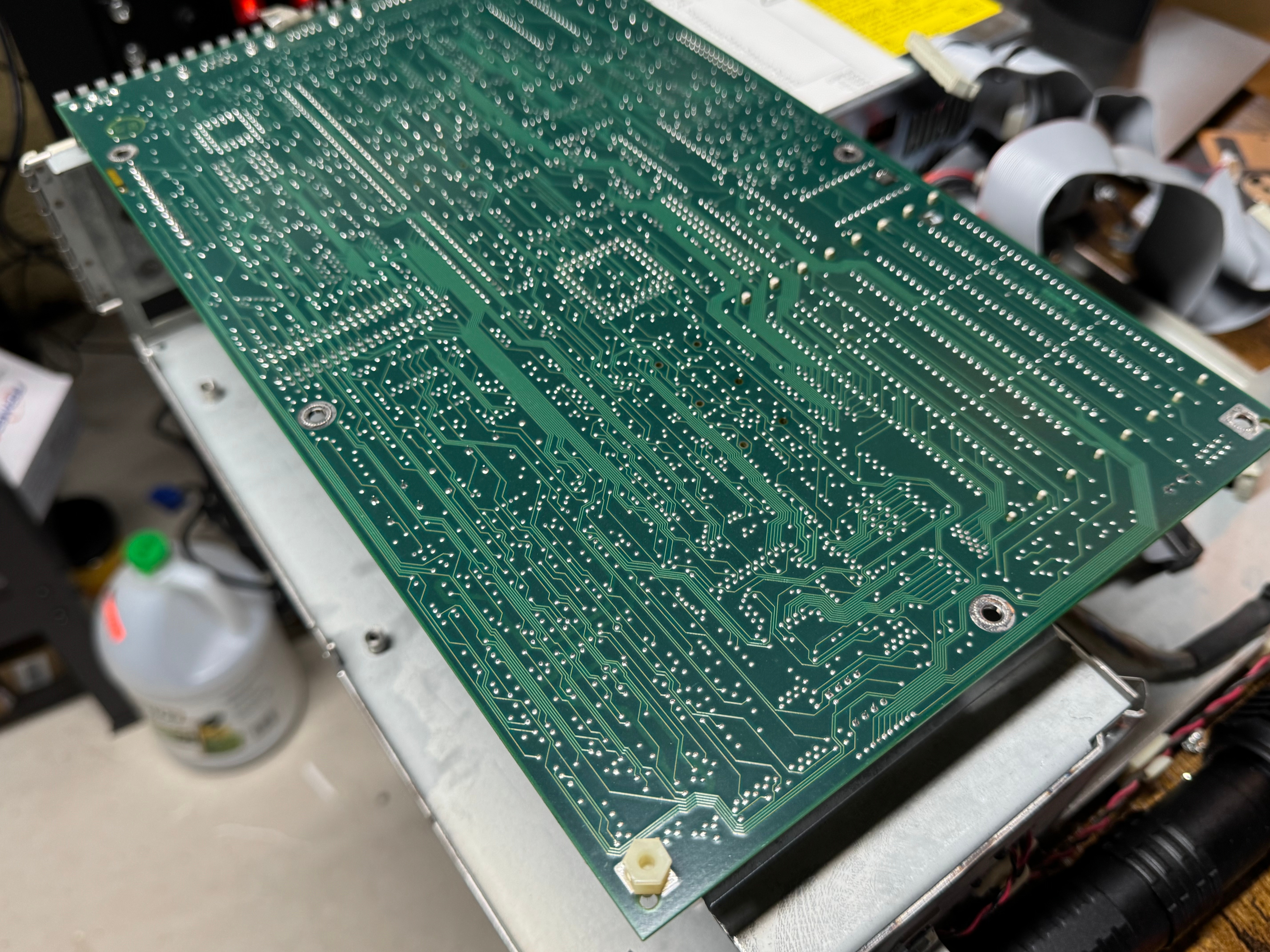
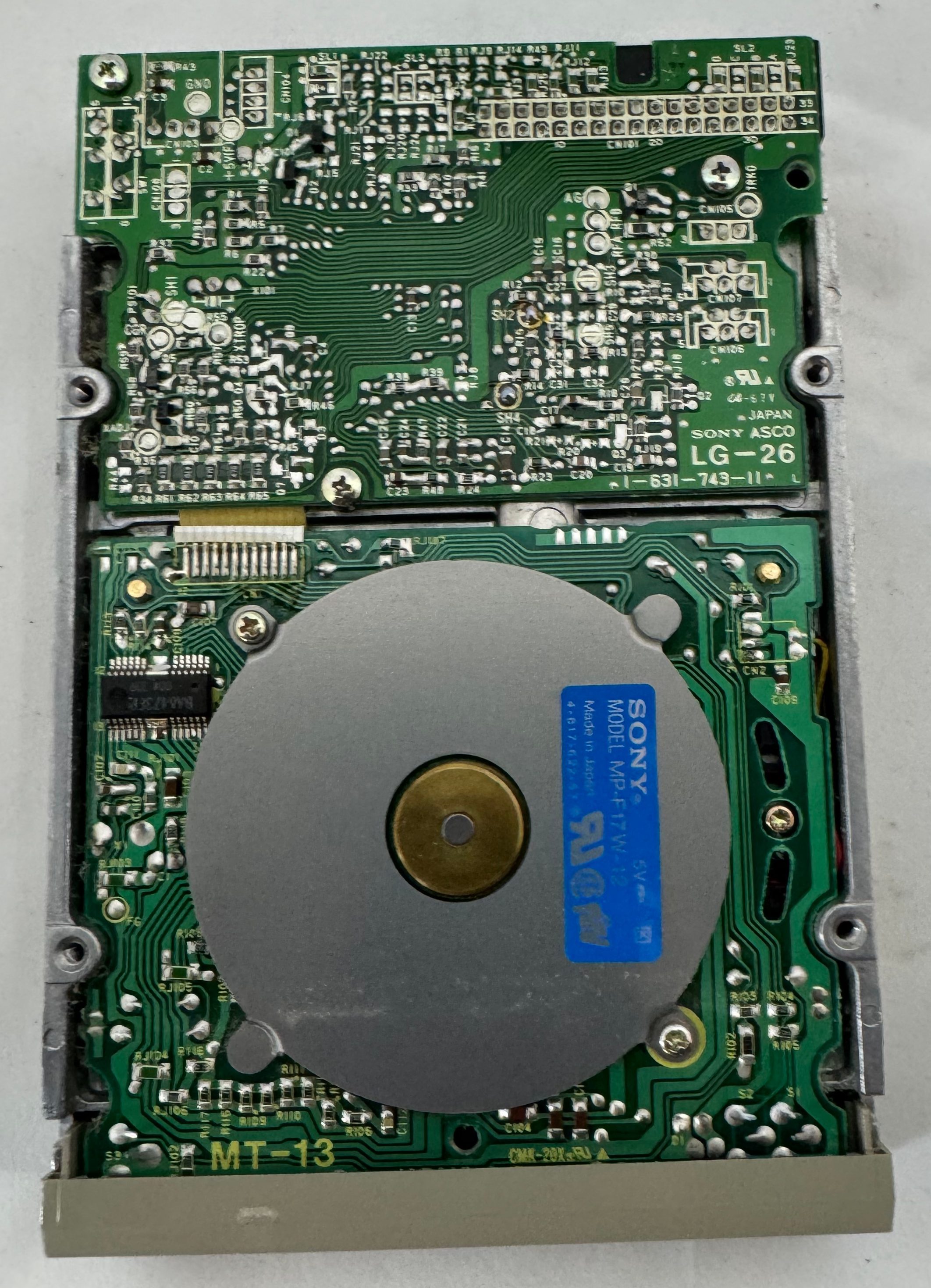
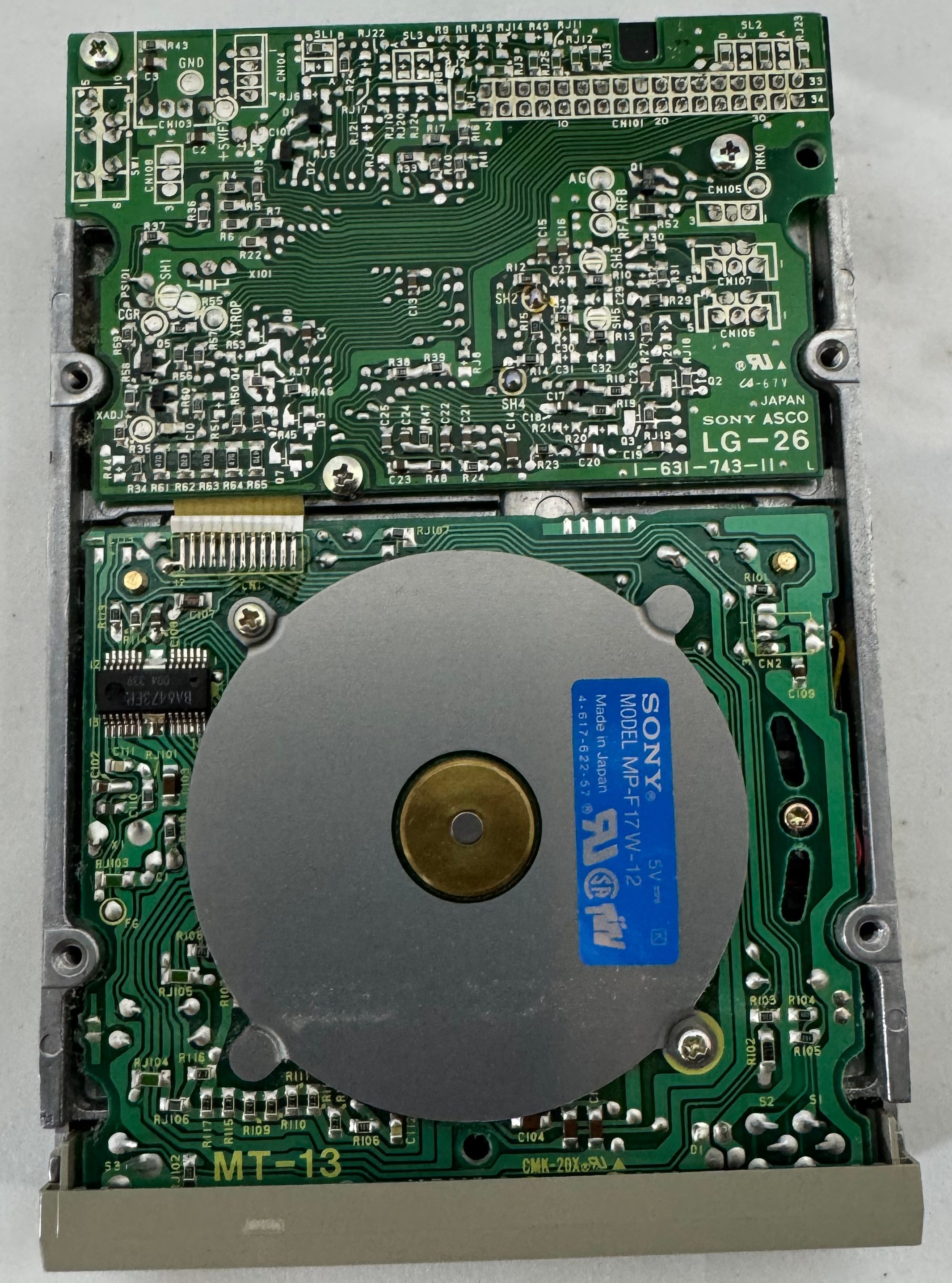
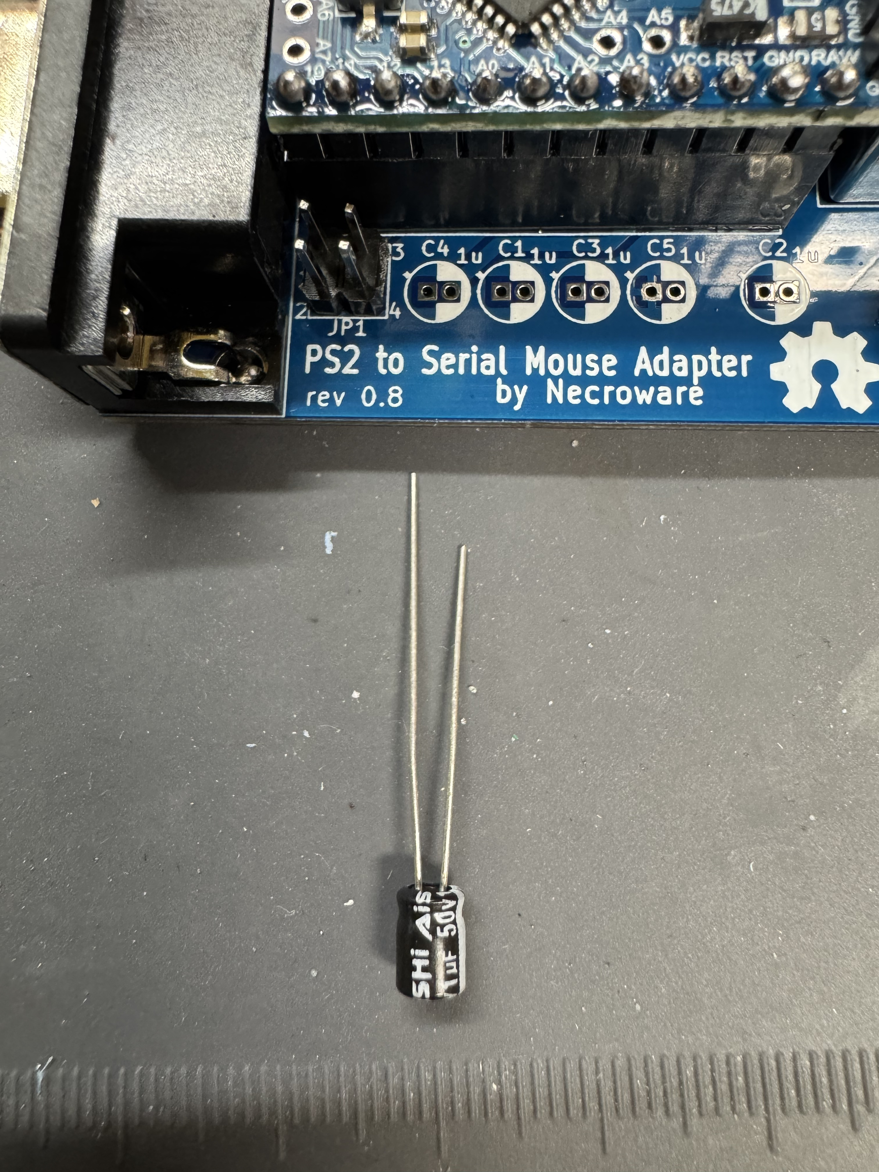
I went back to the shared project and added it to my cart. With the board needing a bunch of small capacitors and the ESP32 soldered to the board, I opted to also have them do full assembly. I submitted the order. A few hours later I got a message on the website and email. The shared project hadn’t set the PCB layer count, and I had accepted whatever was default (incorrect). I flagged https://vroland.github.io/epdiy-hardware/ as the source of the project and said I wasn’t sure how many layers it was. They came back quickly saying the board was a 4-layer board with 1oz for each copper layer, and it was resubmitted for approval. I was very glad someone who knew what they were doing was reviewing the board before sending it off. Later, I got another message from someone double checking the polarity of a LED on the board, and I was able to look up from the design and verify it with them.
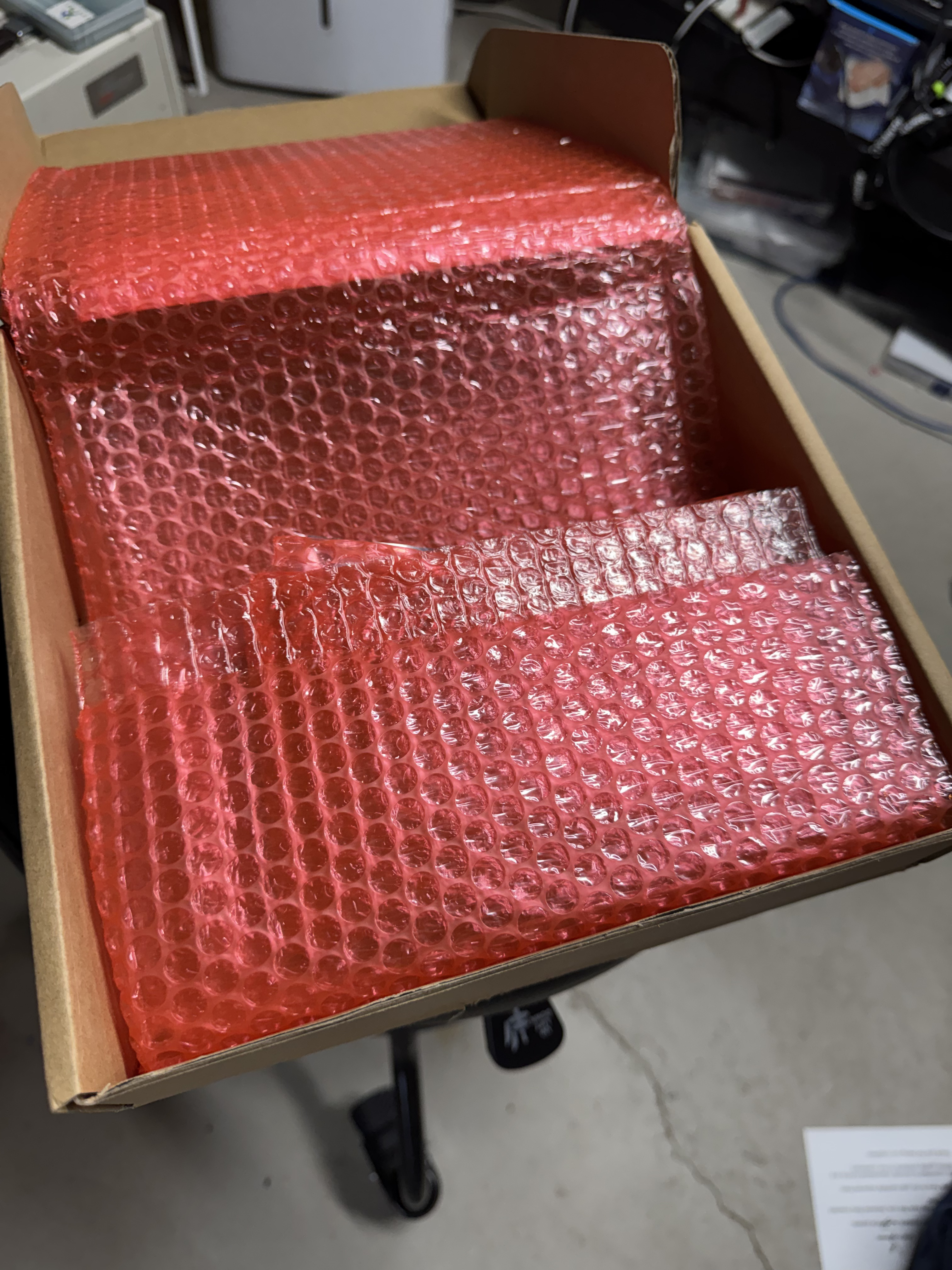
Boards have to be ordered in sets of at least 5, I got 5. I planned to pay to have 4 assembled; I would have extras and would be able to use them in future projects. 5 boards were $25.97 + shipping and took 4 days or so to build. Then 4 boards, assembly and parts all came to $110.59, that part took about 20 days. Most of that cost was the parts (which they handle). Then shipping was around $50 at the time. All together this put each PCB at around $40. I got updates along the way, and this let me work on other aspects of the project while I followed the boards’ progress.
I plan to use PCBWay again in the future for circuit boards I may need created since 5 for ~$26 seemed like a great deal on these complicated ones. I am also curious about using them for CNC on some future projects where parts may need to be made out of metal. 3D printing works for a lot of my needs but a few parts may need to be metal.

Controller Design
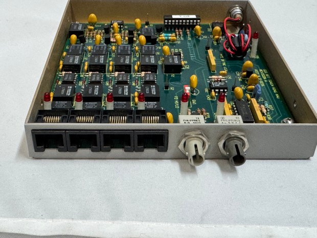
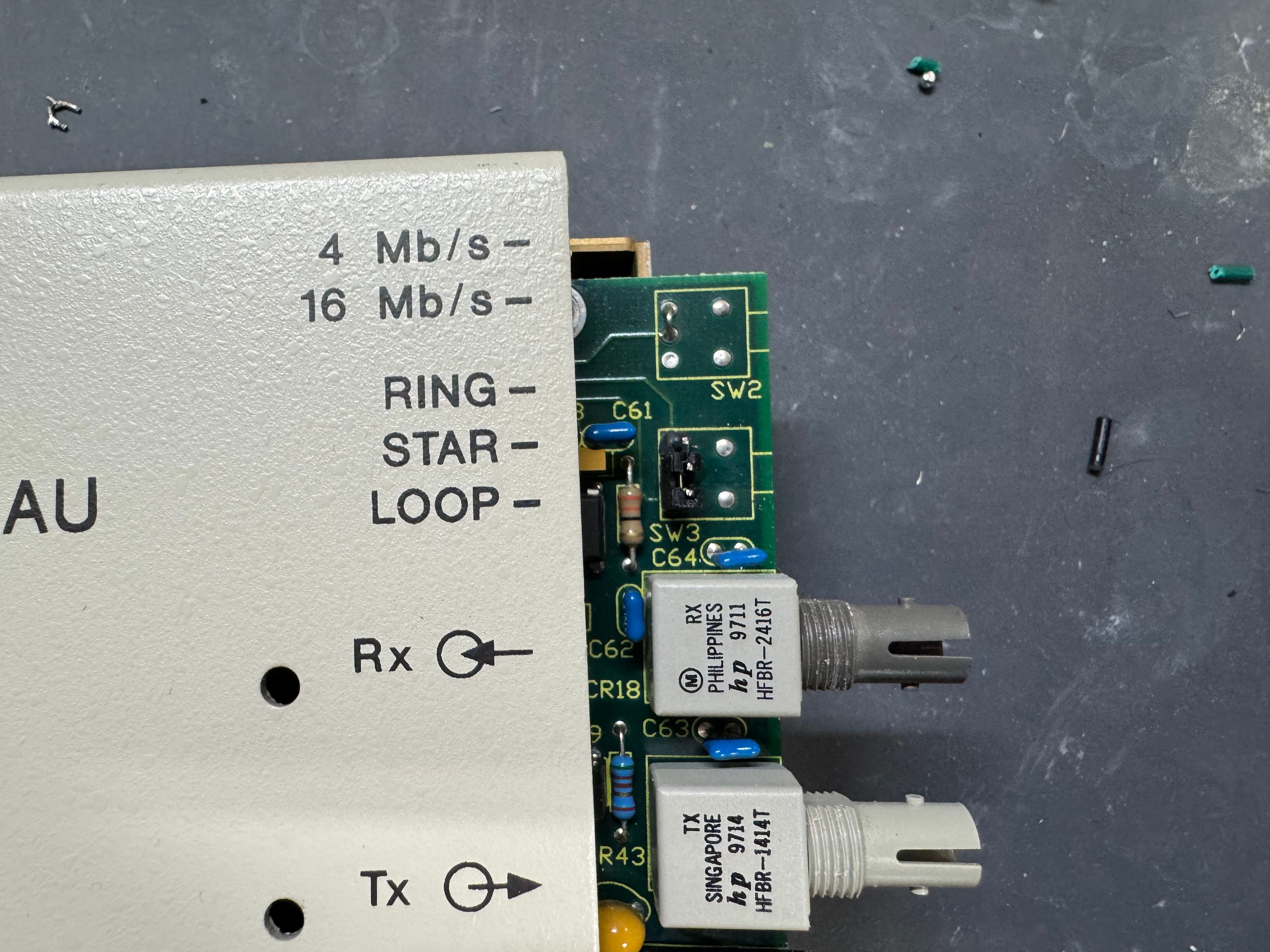
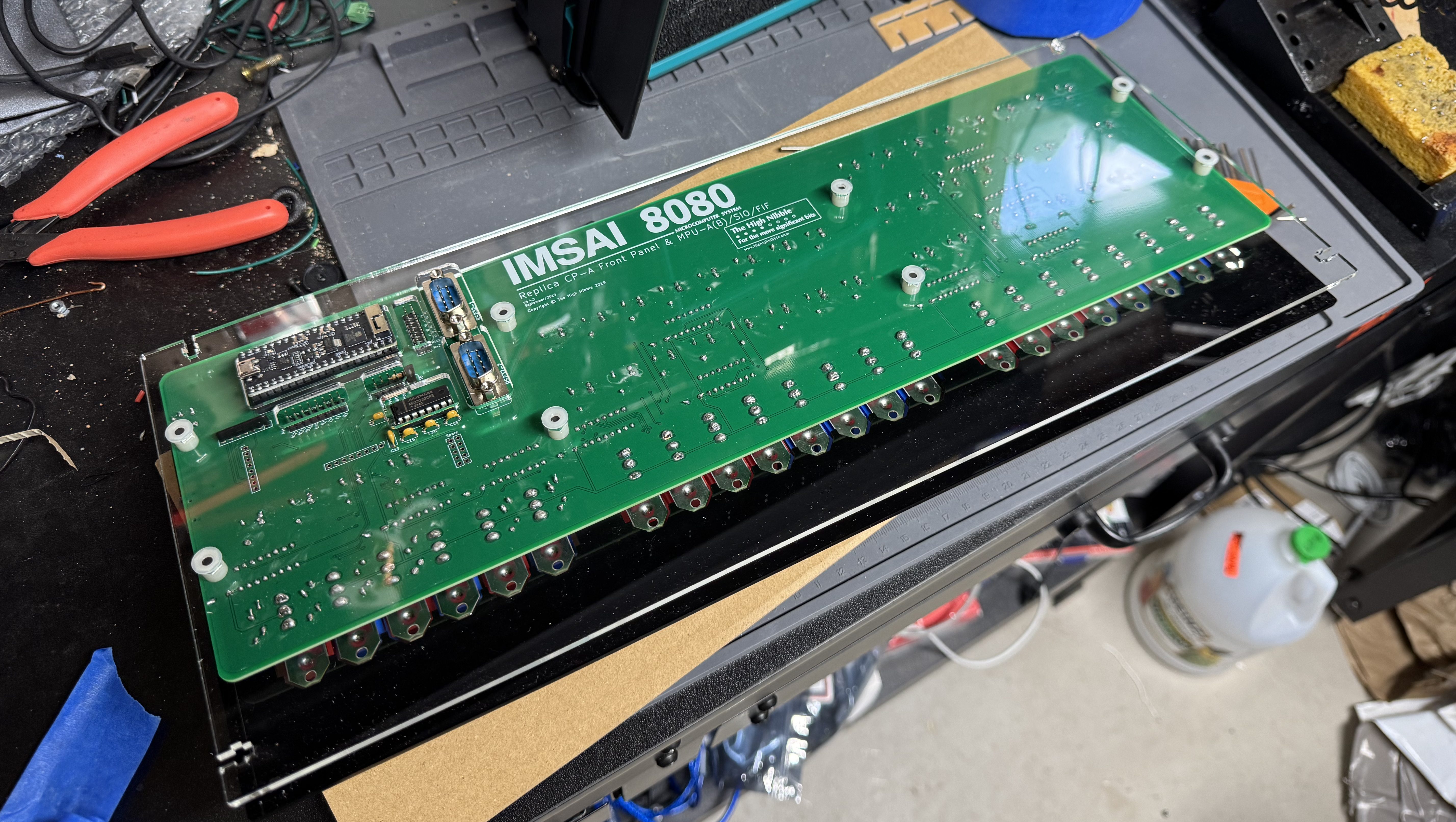
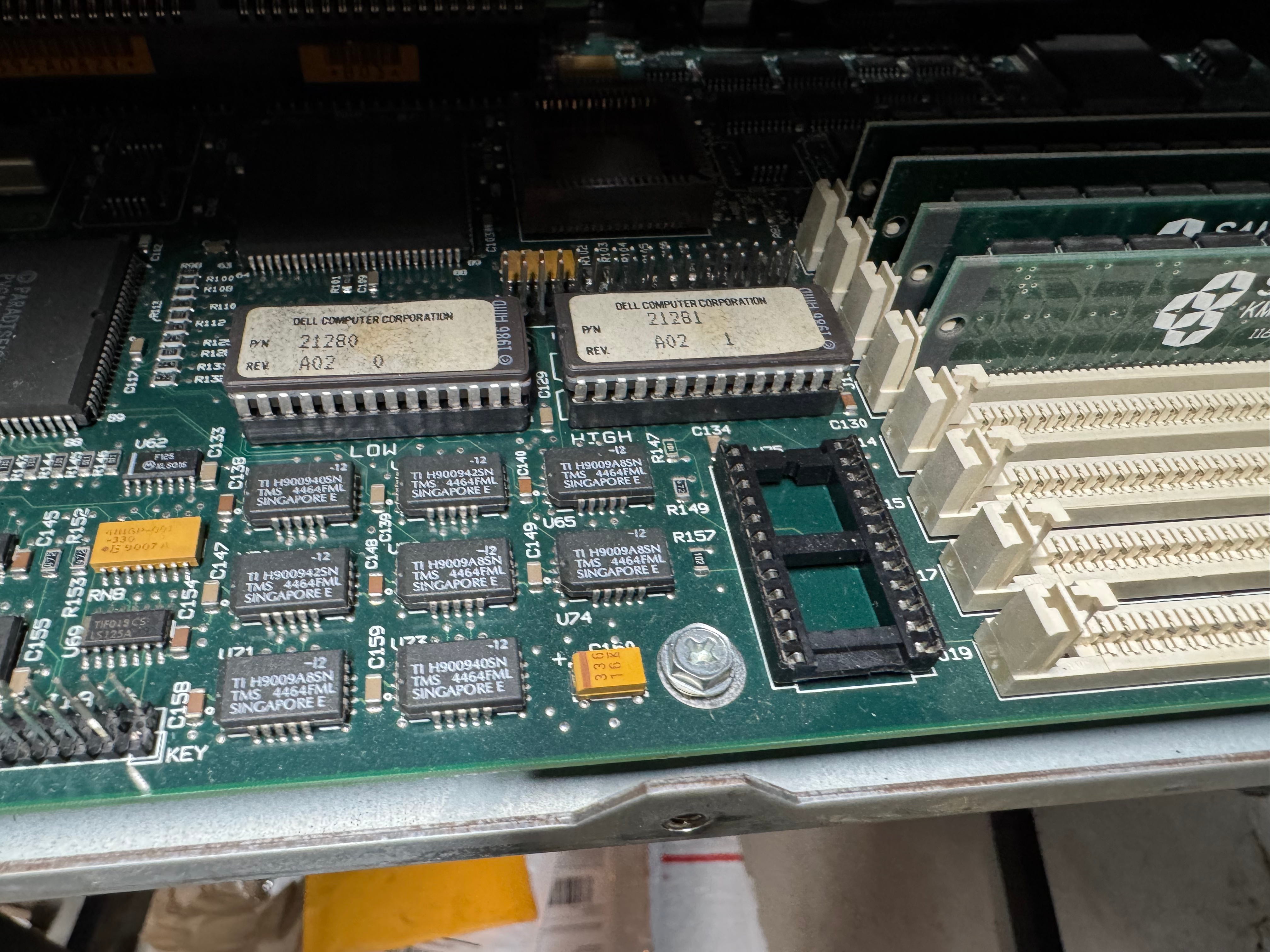
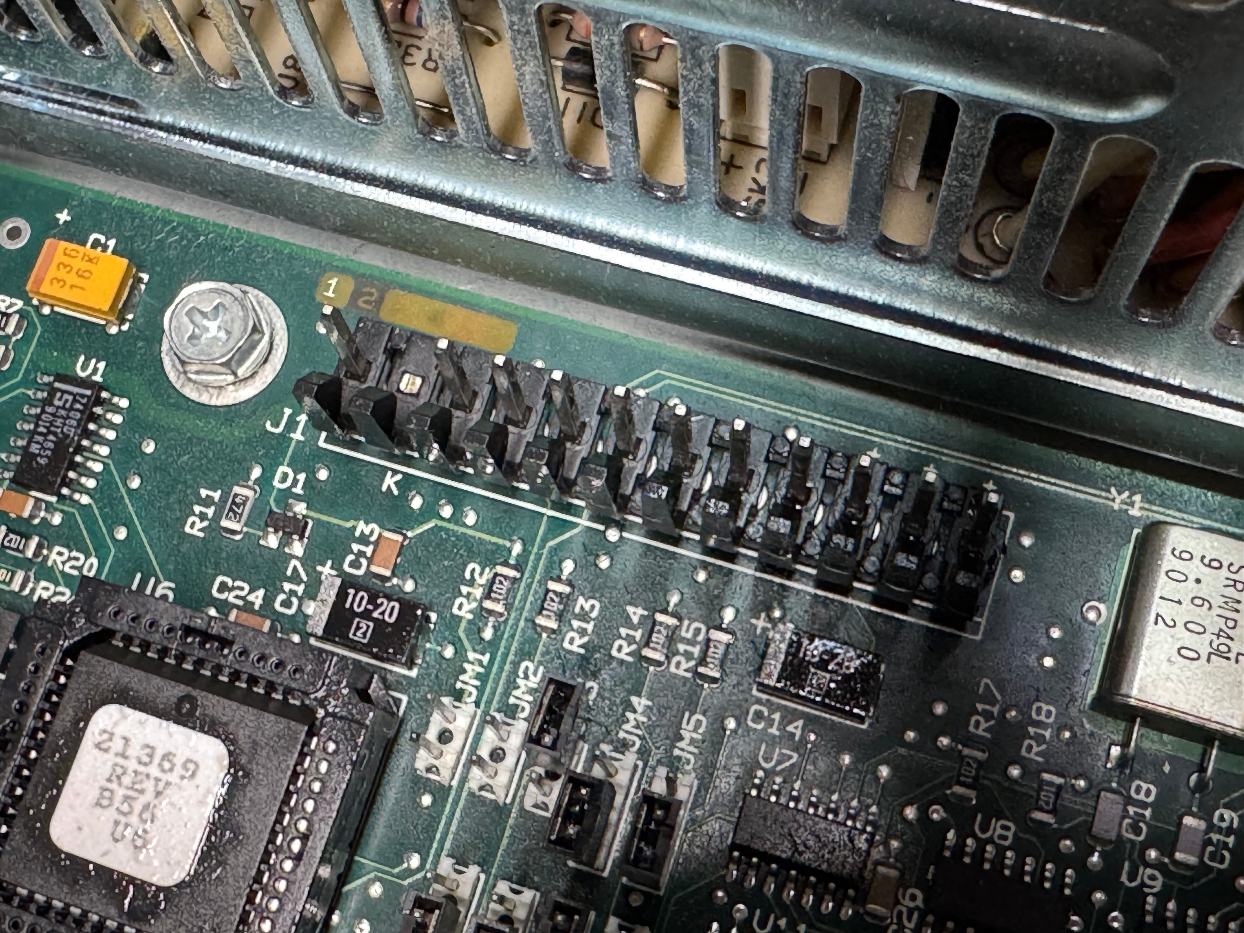
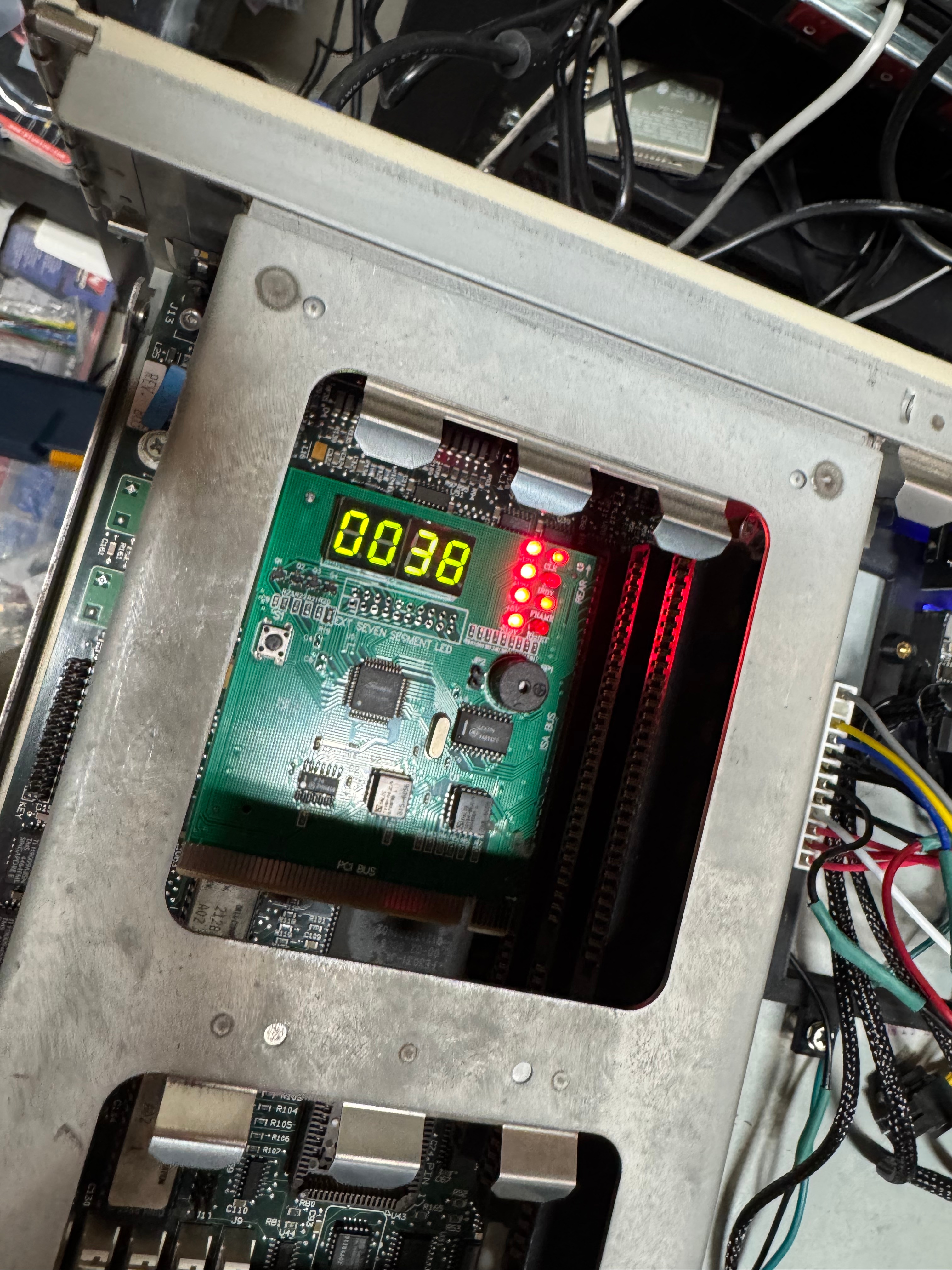
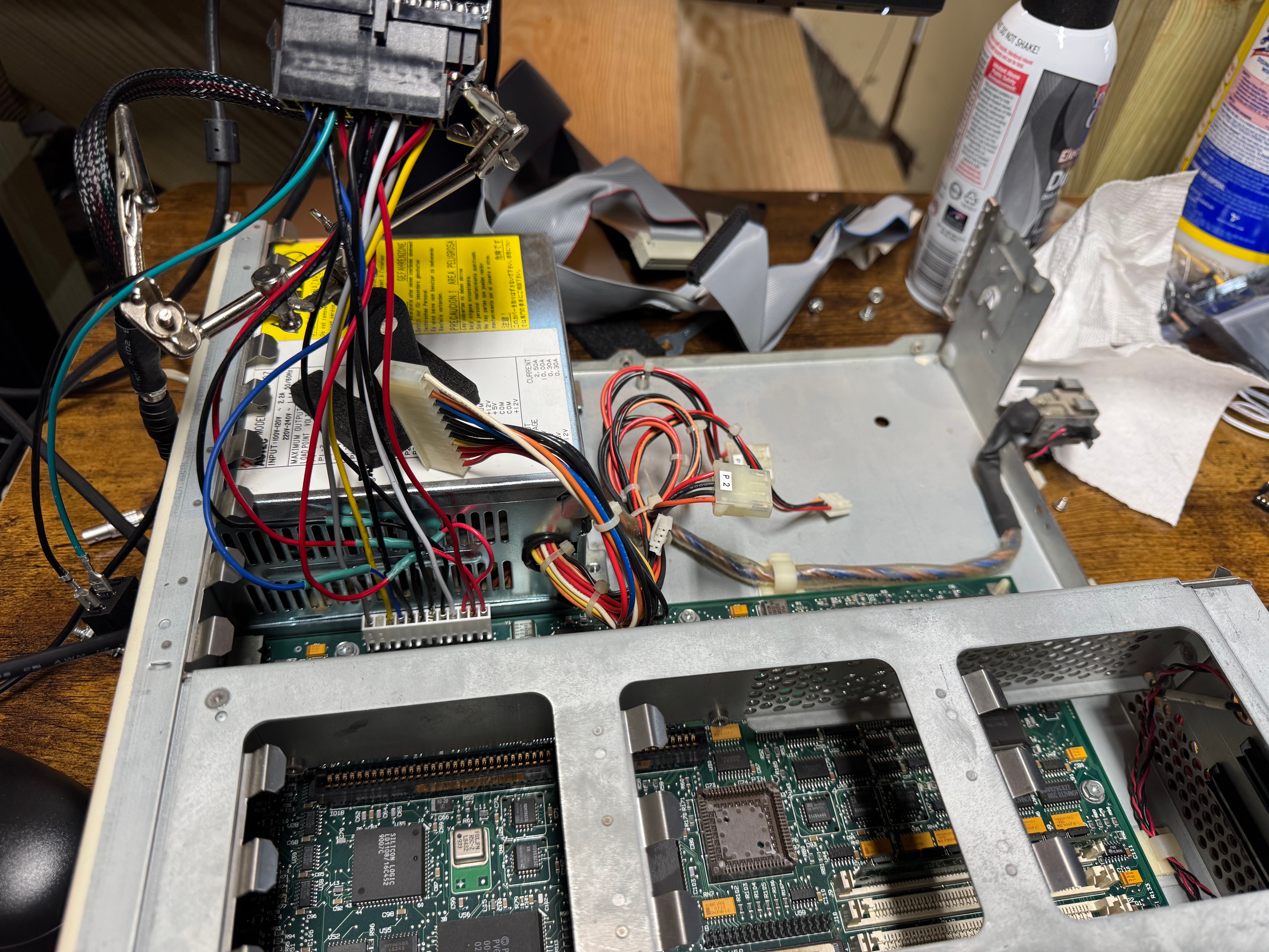
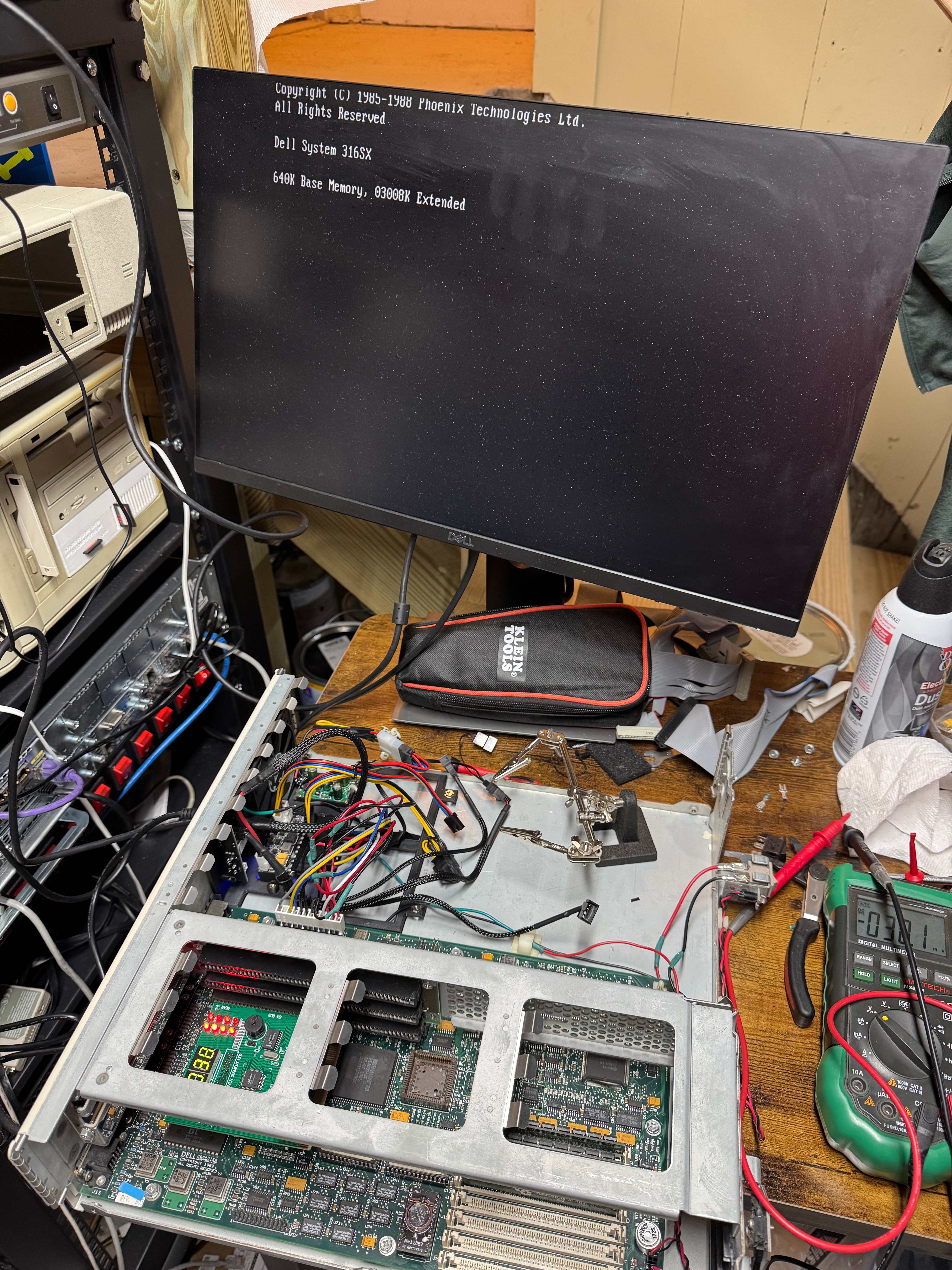
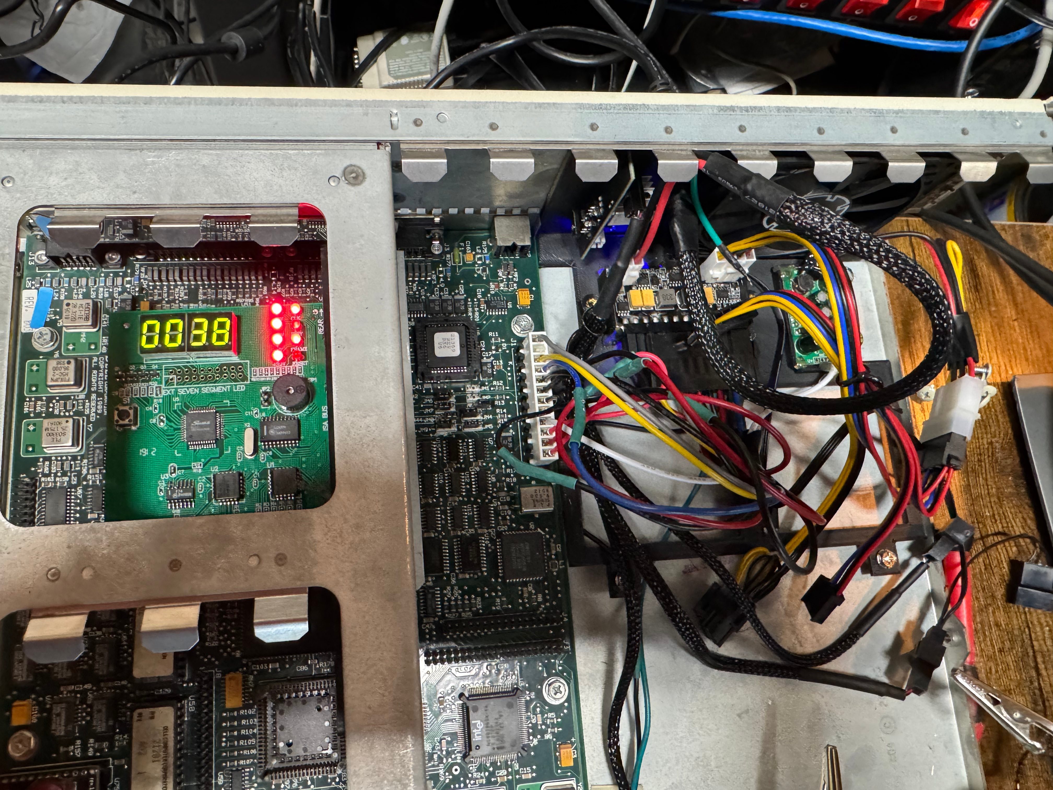
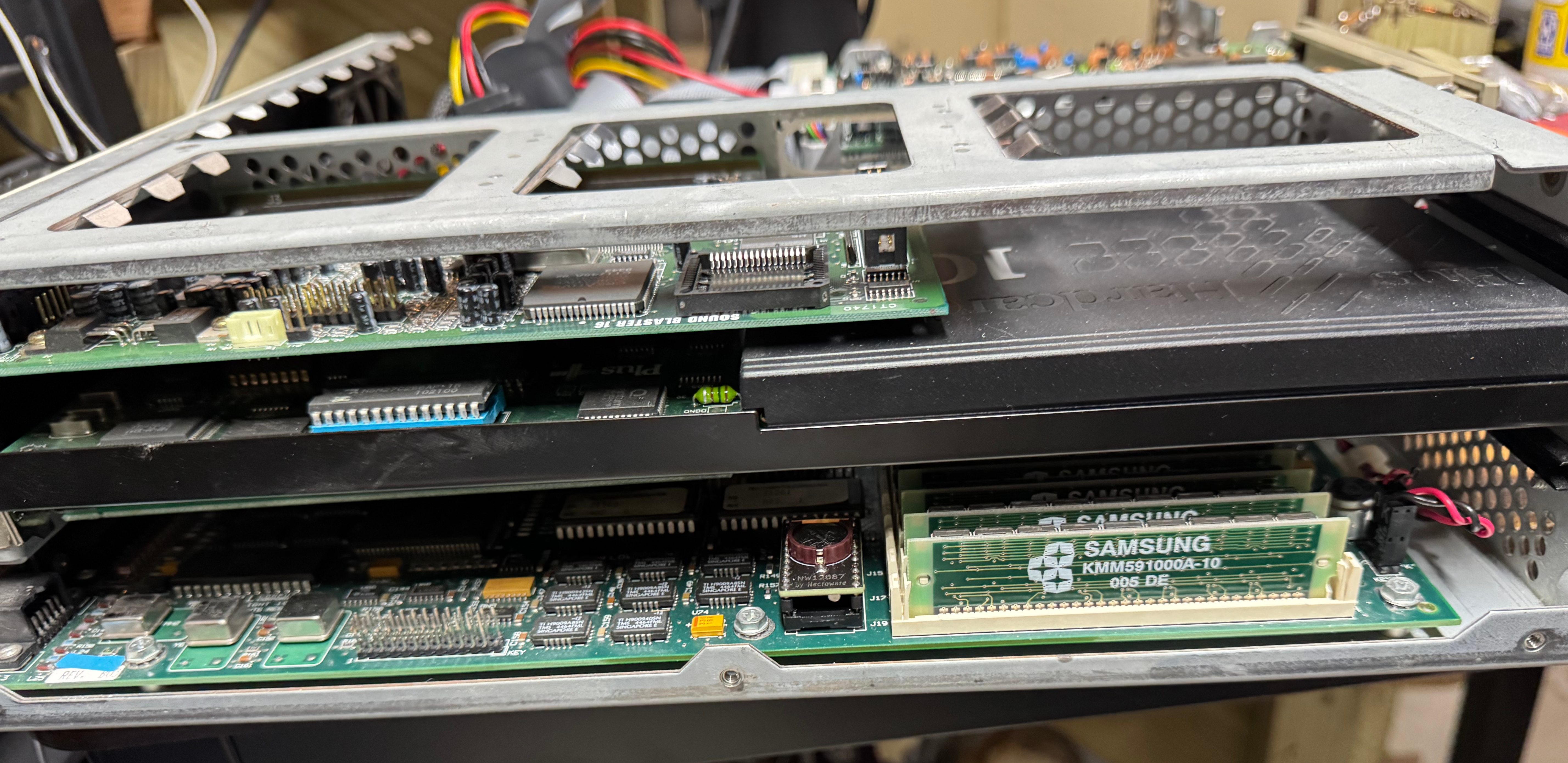
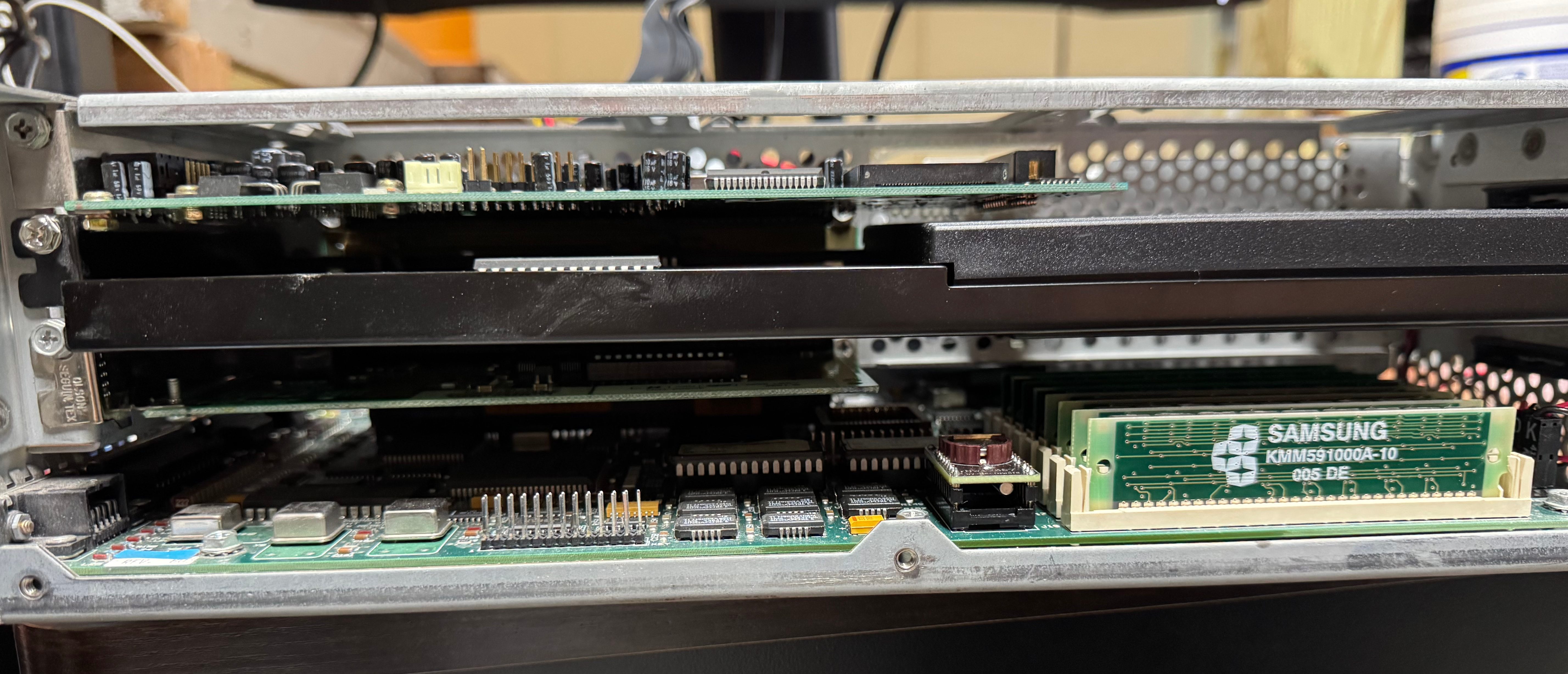
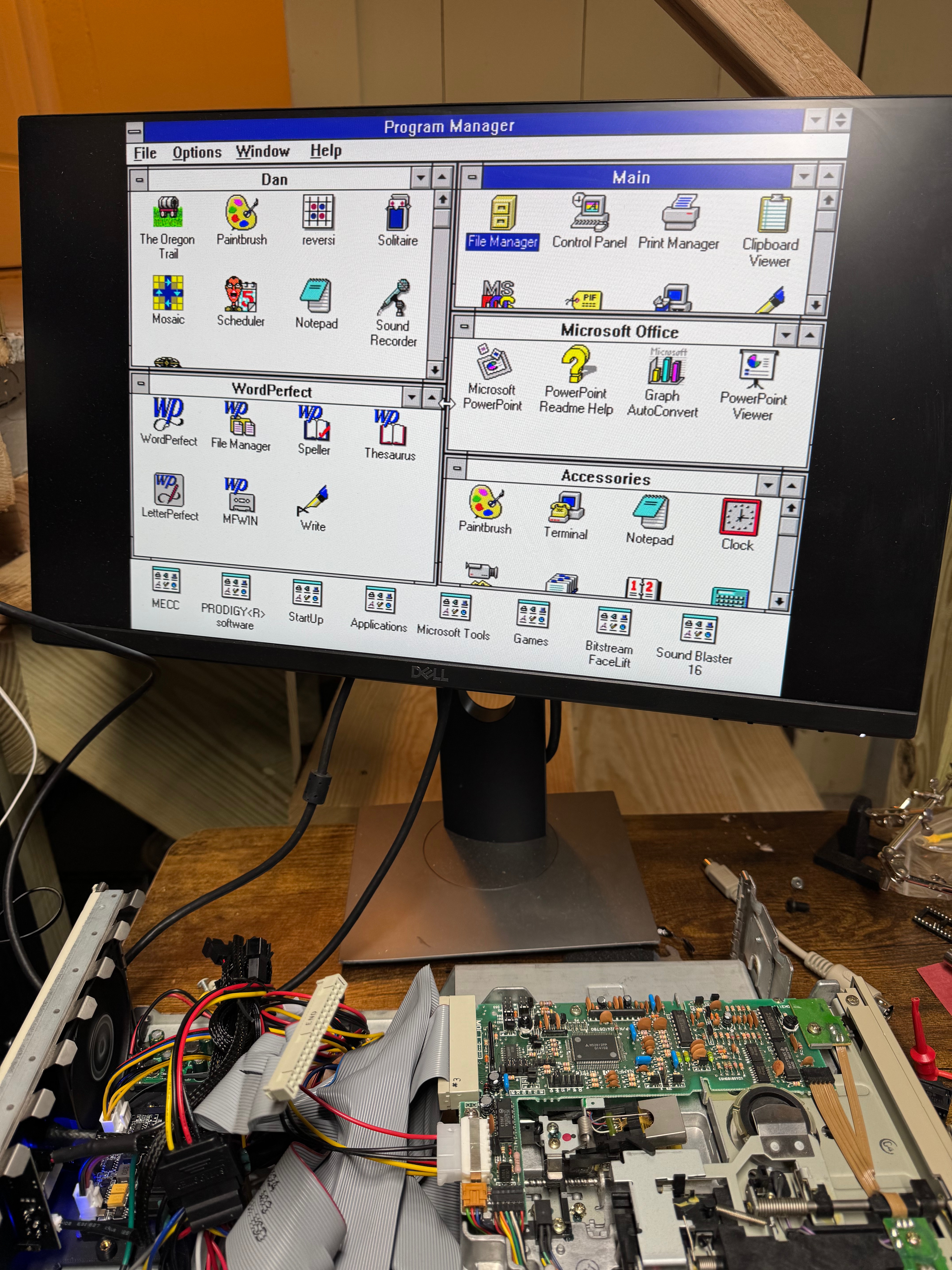
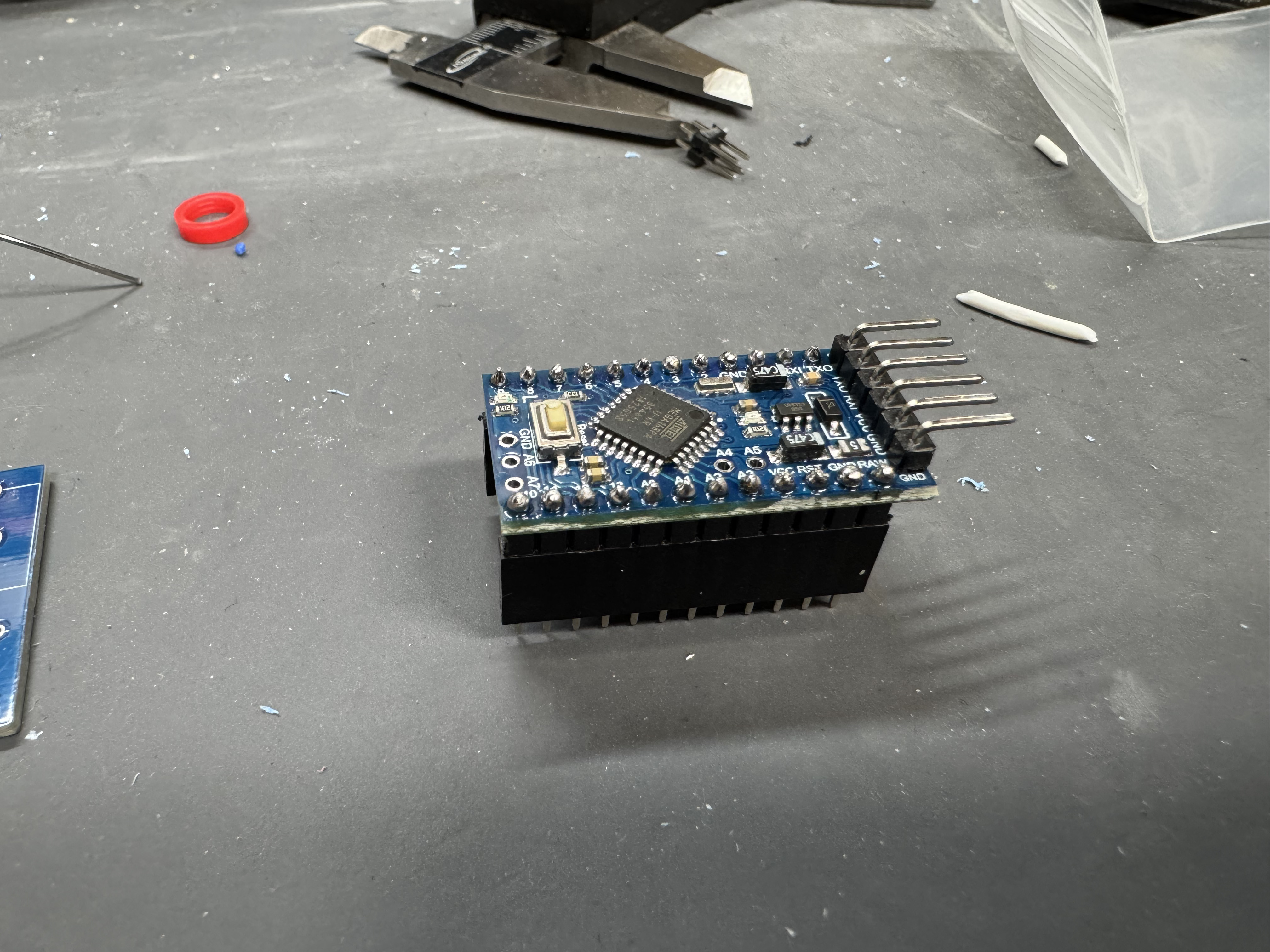
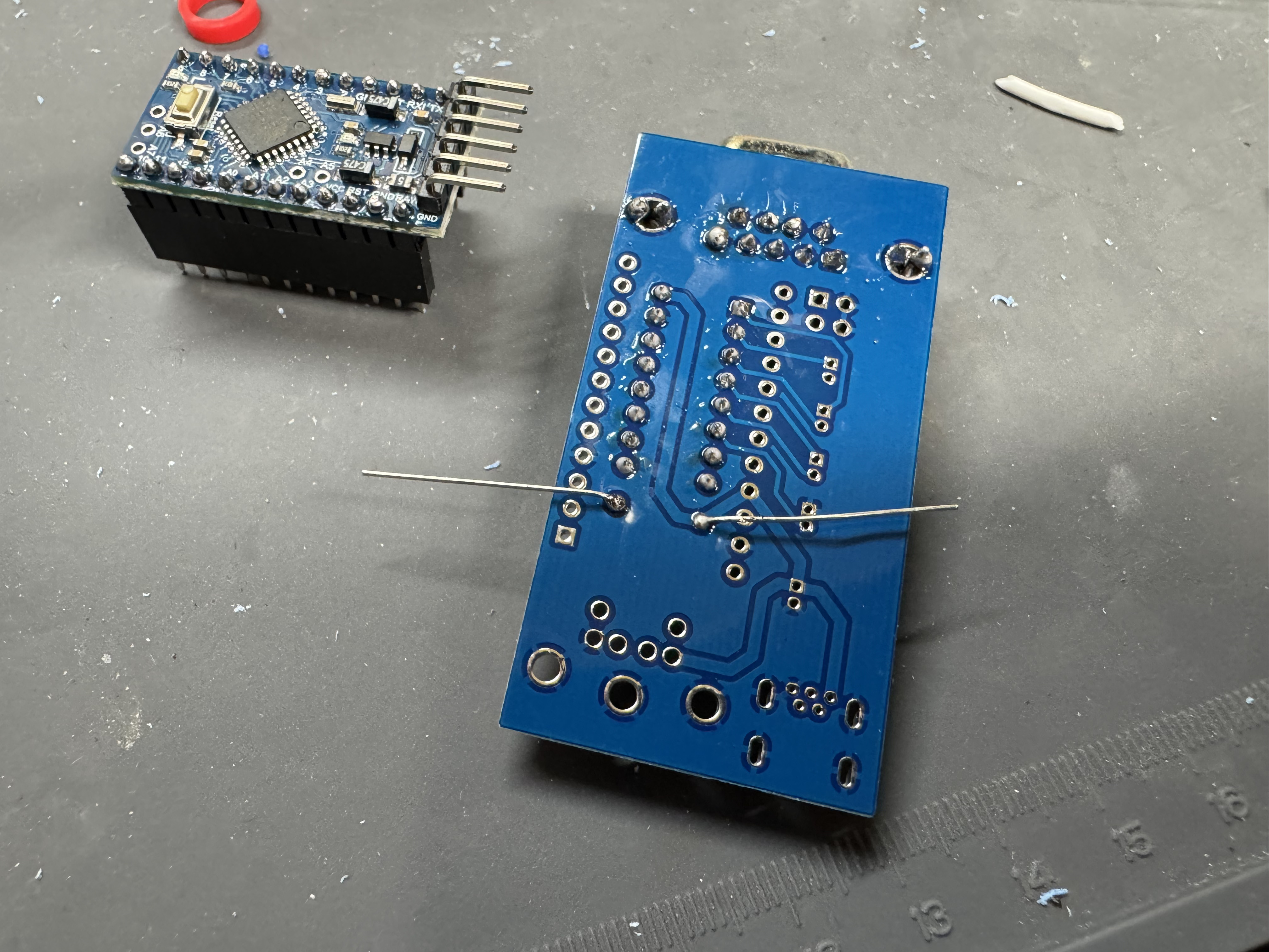
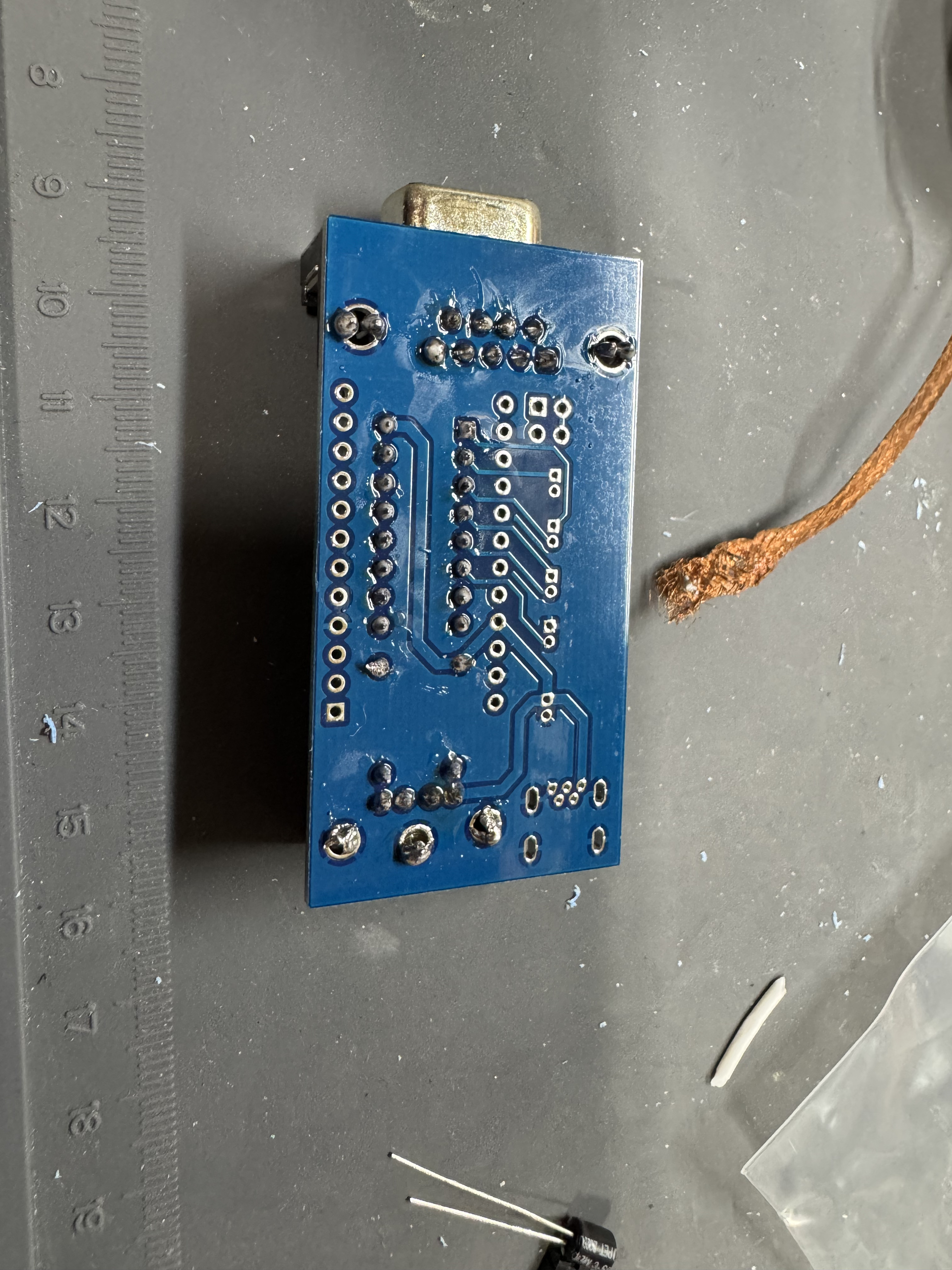
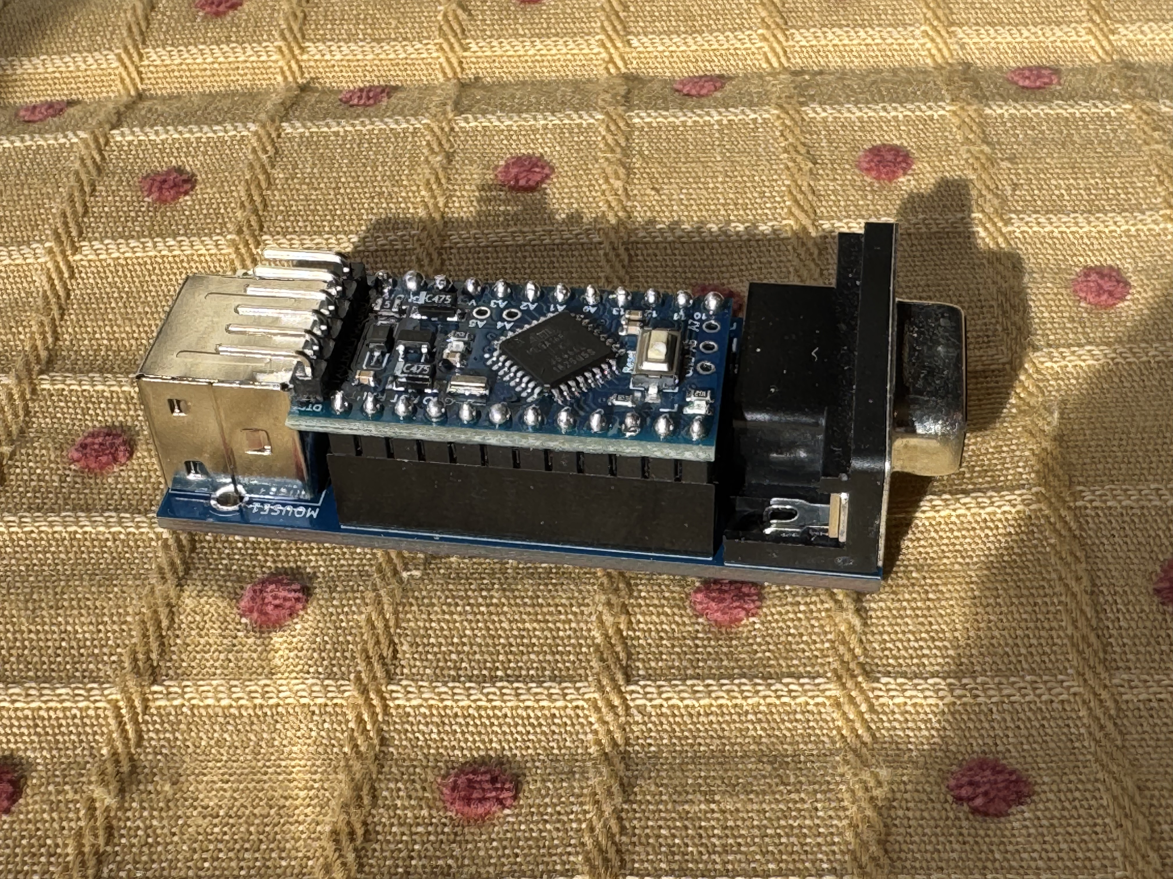
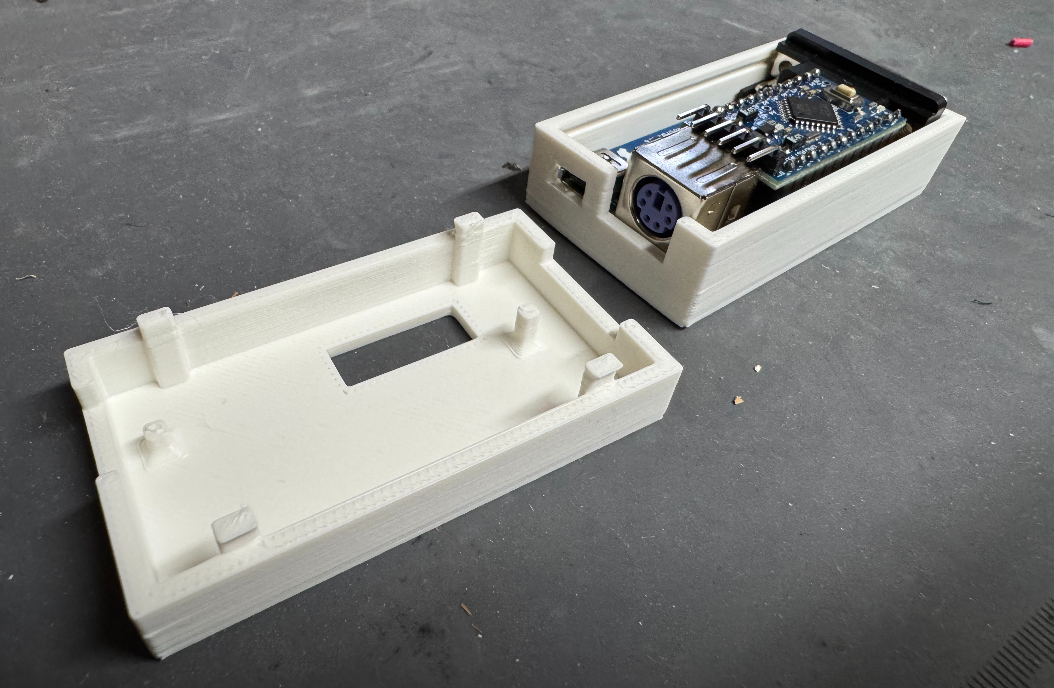
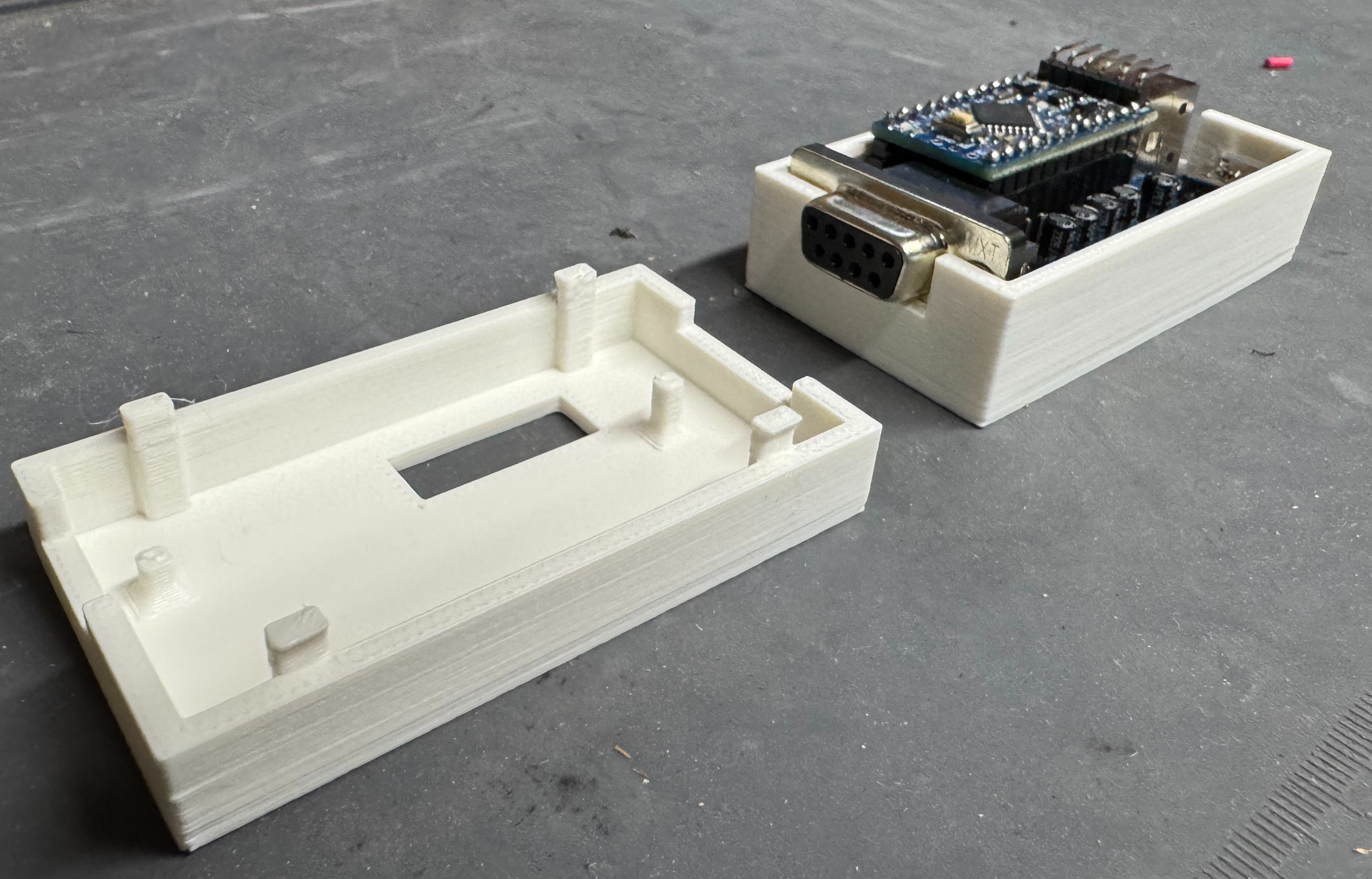
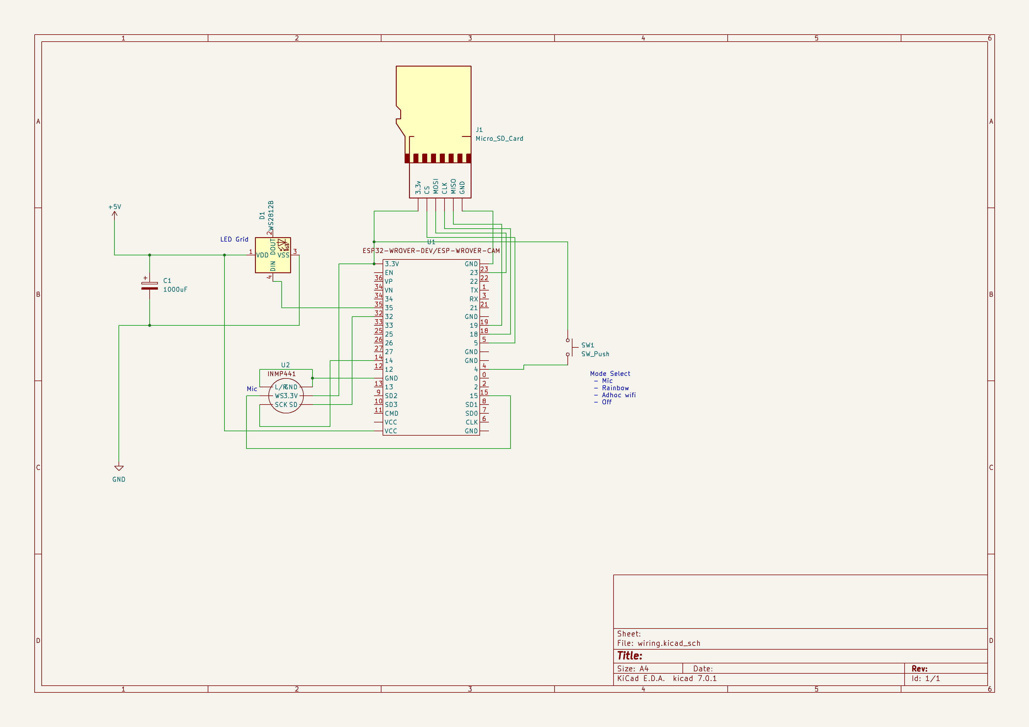
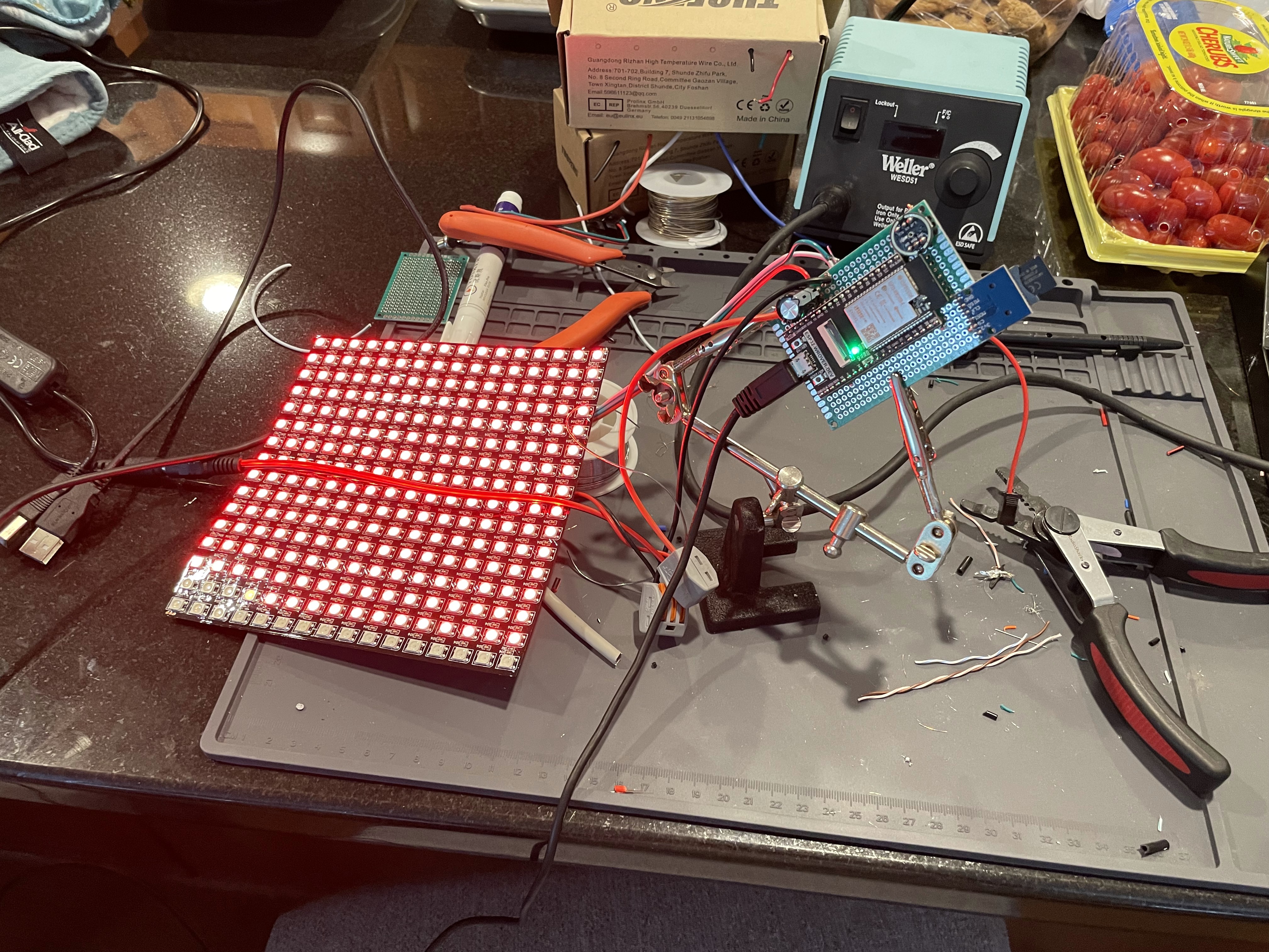
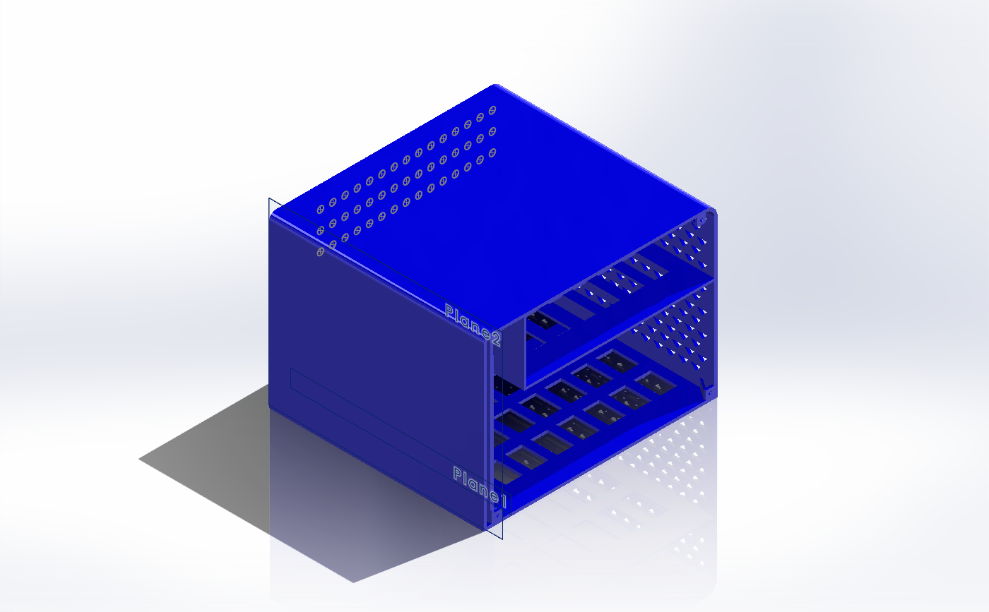
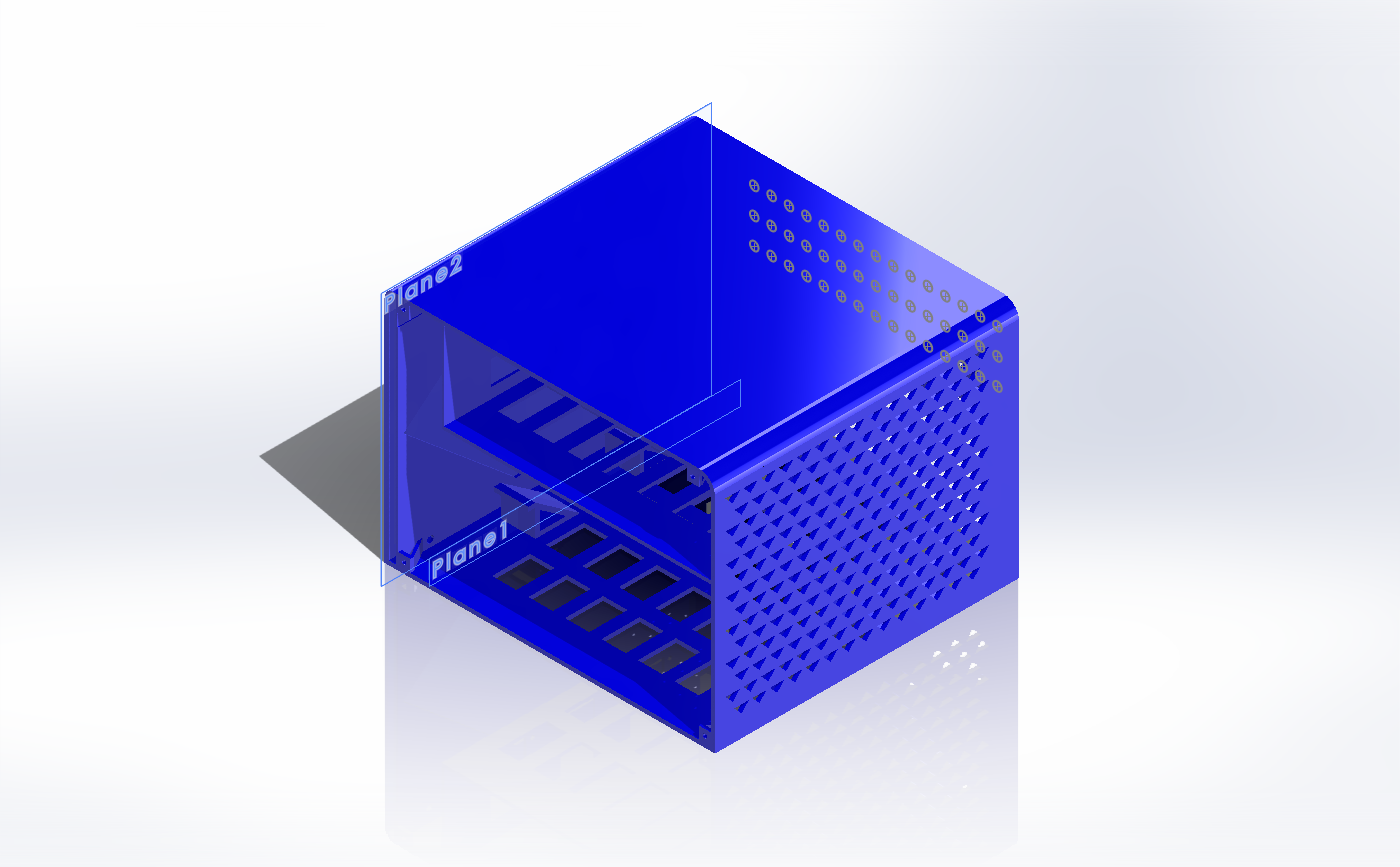
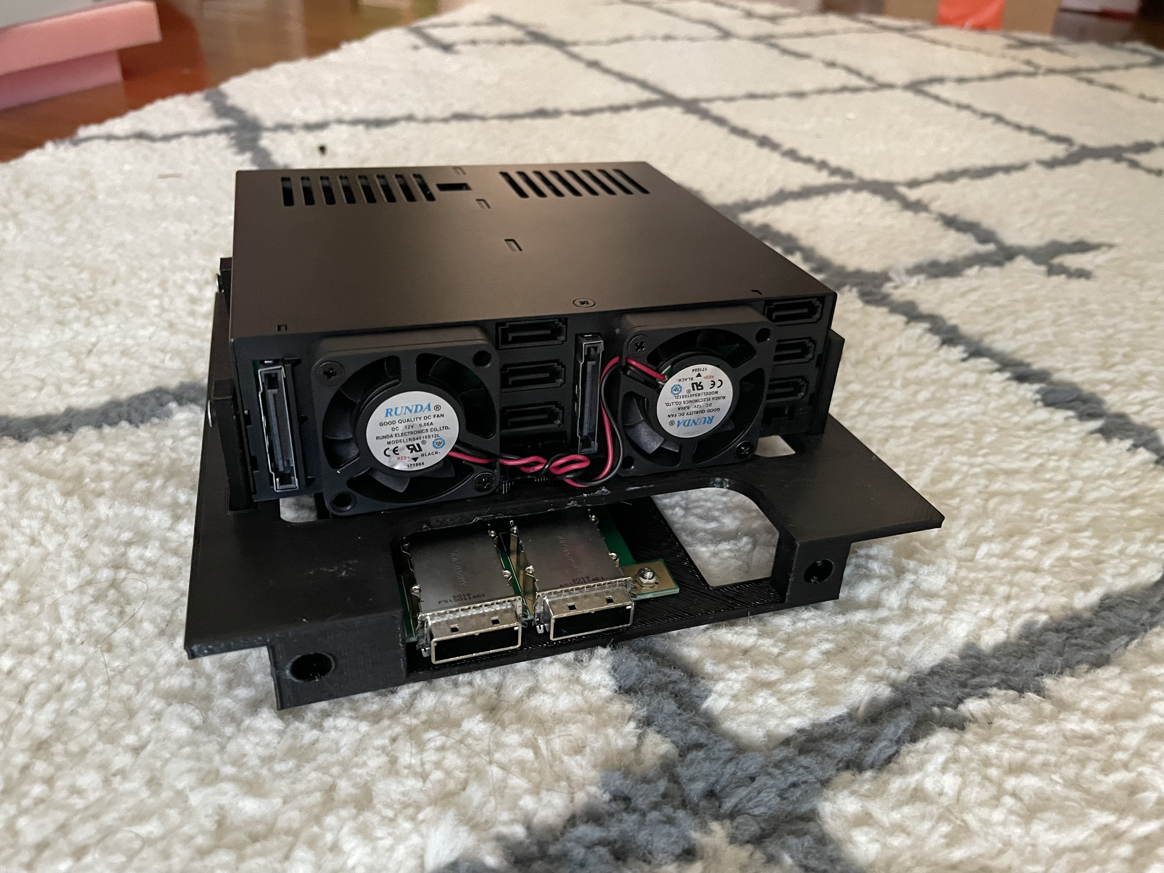
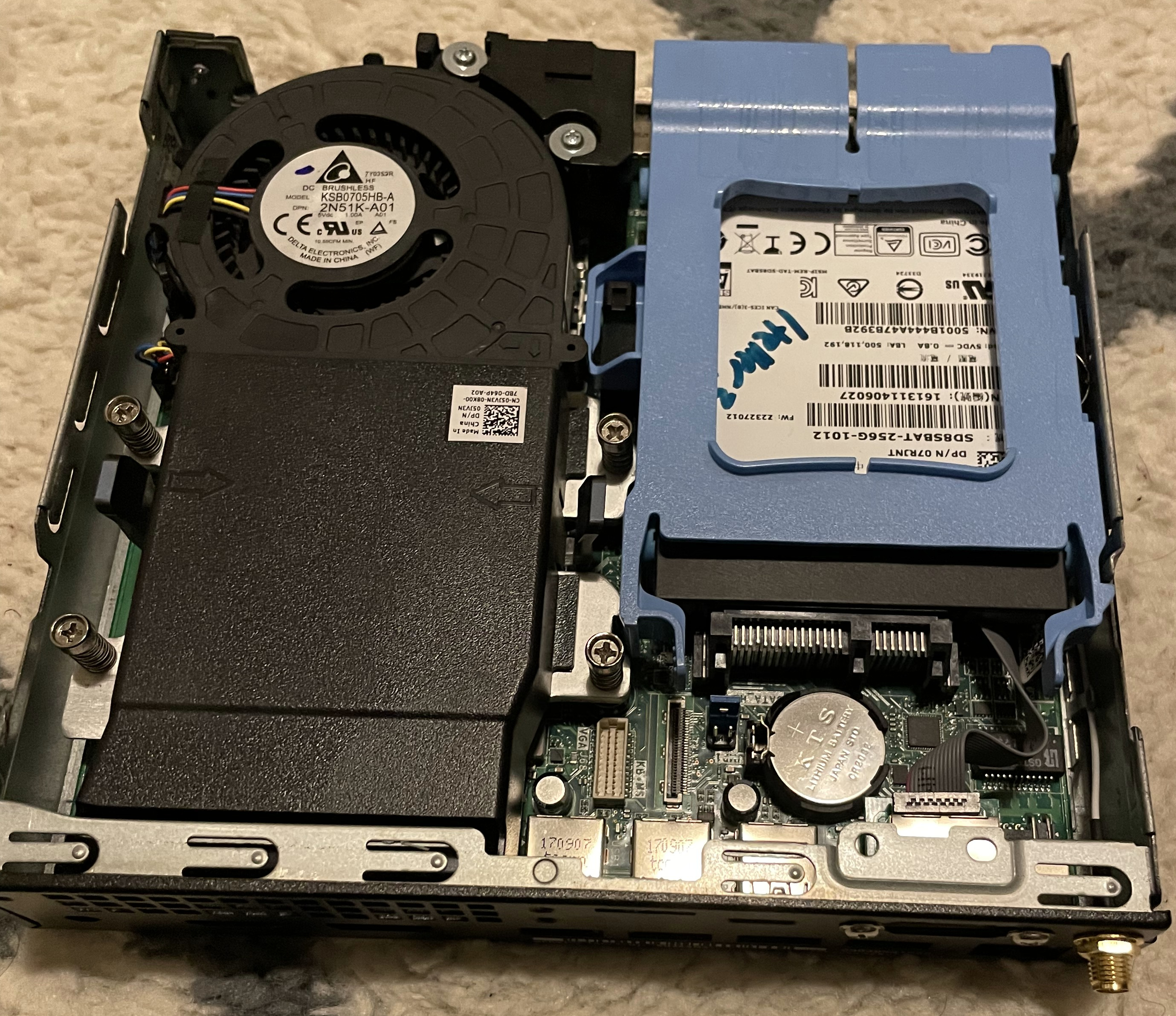
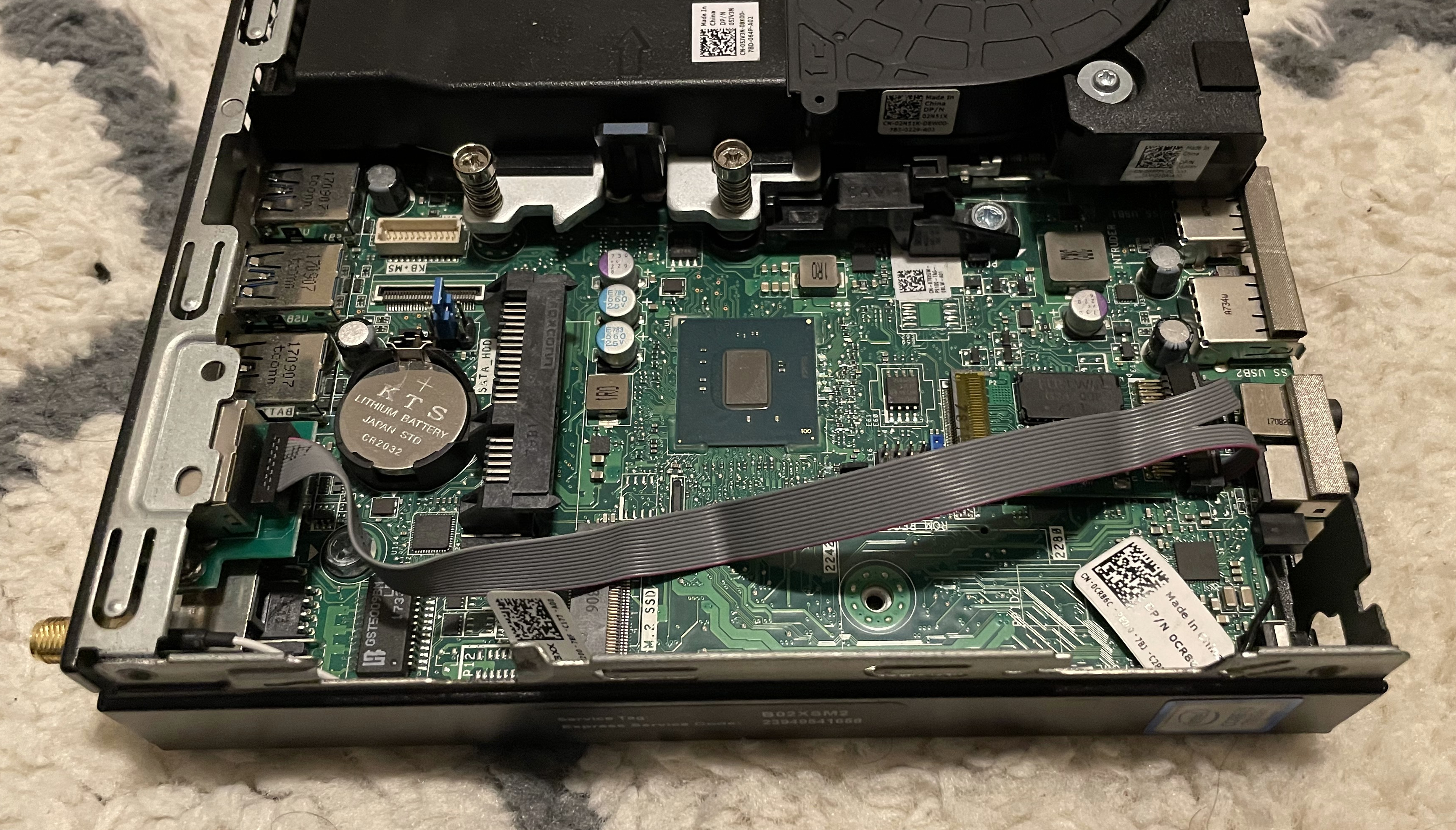
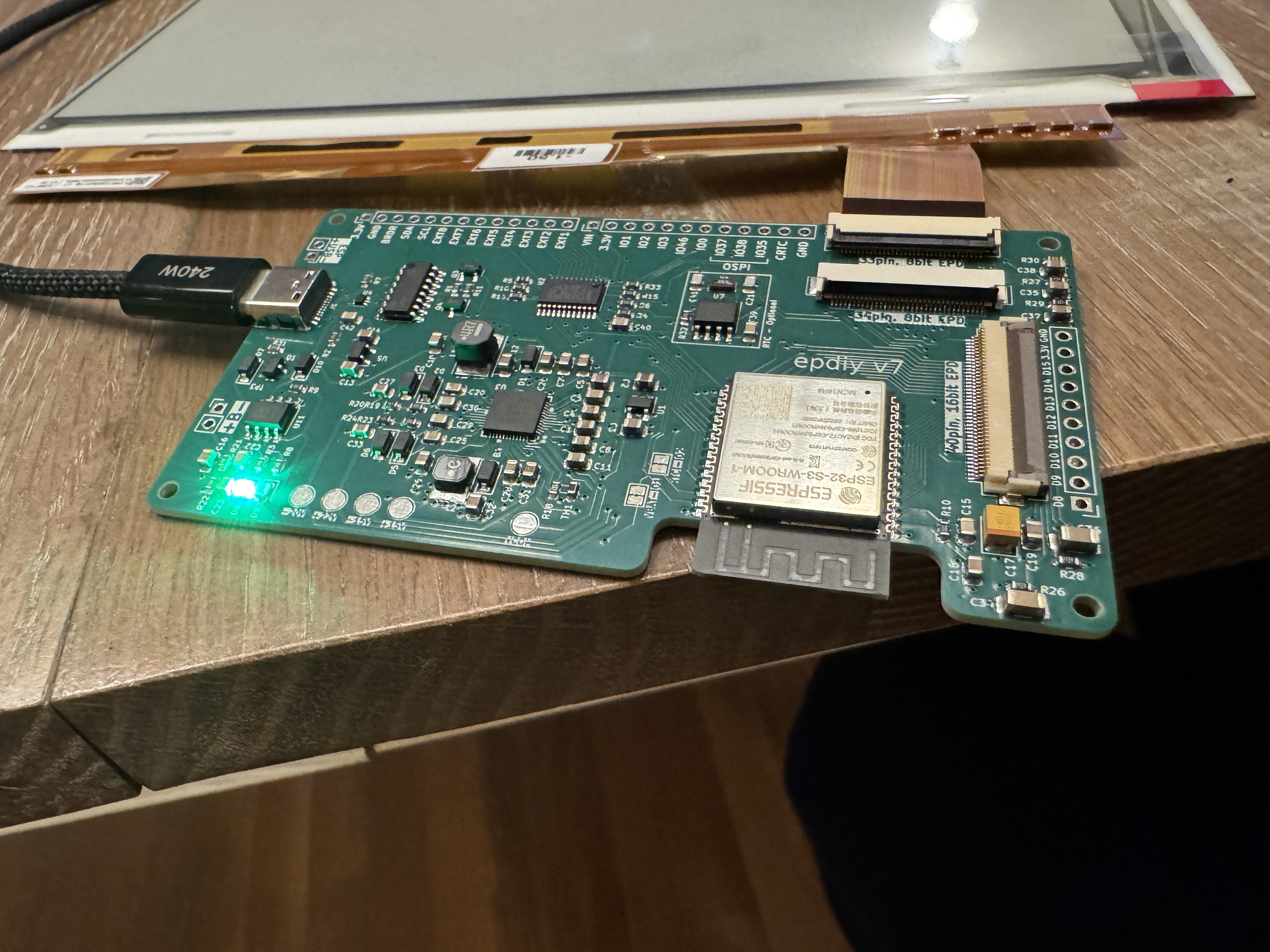
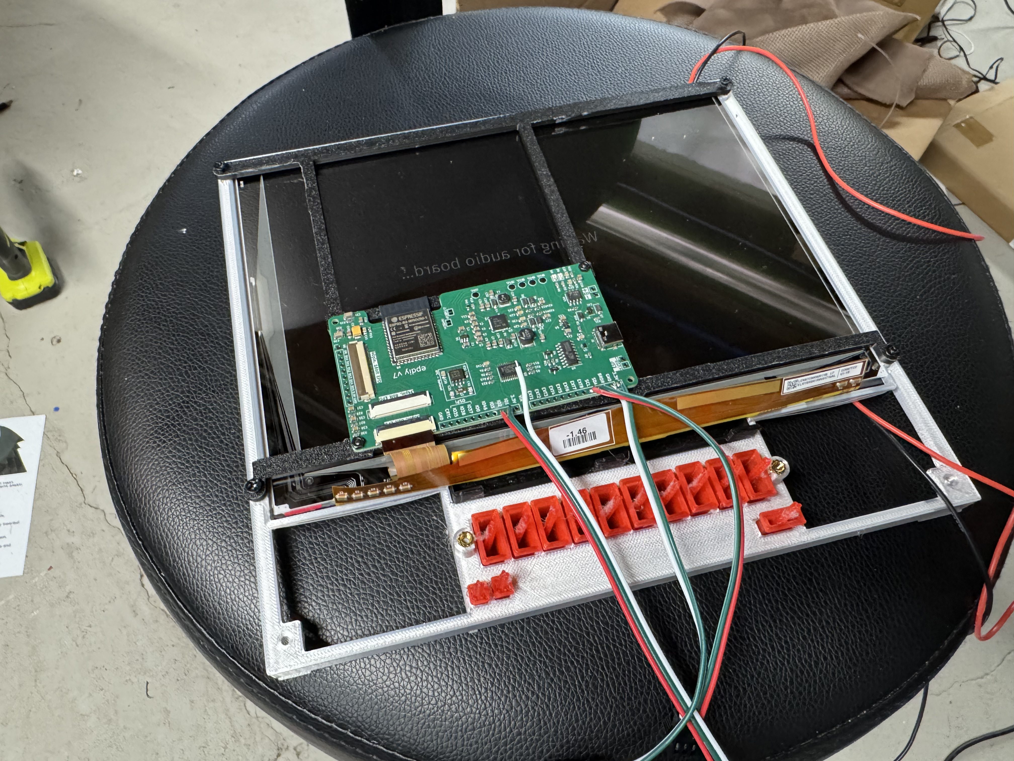
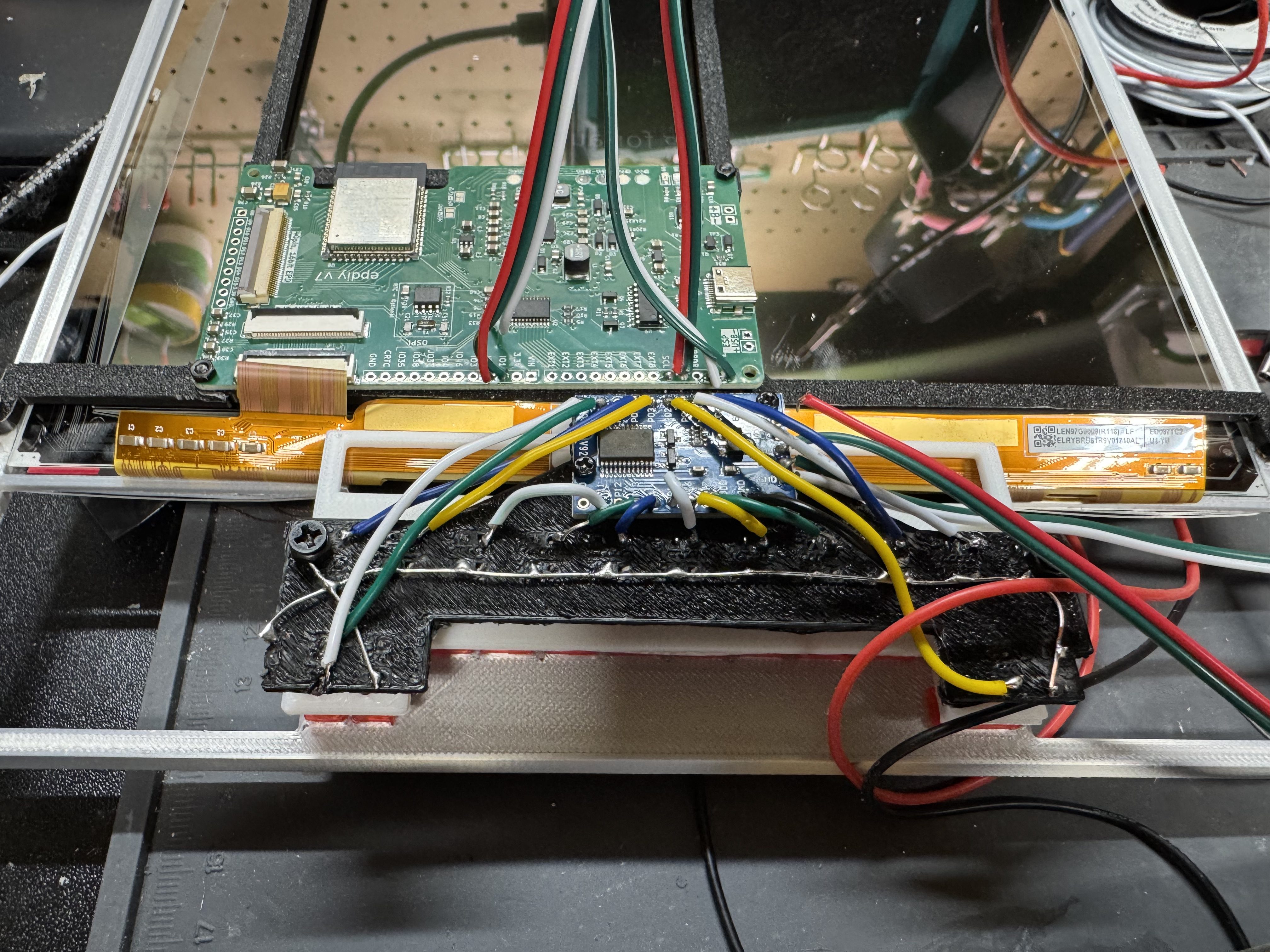
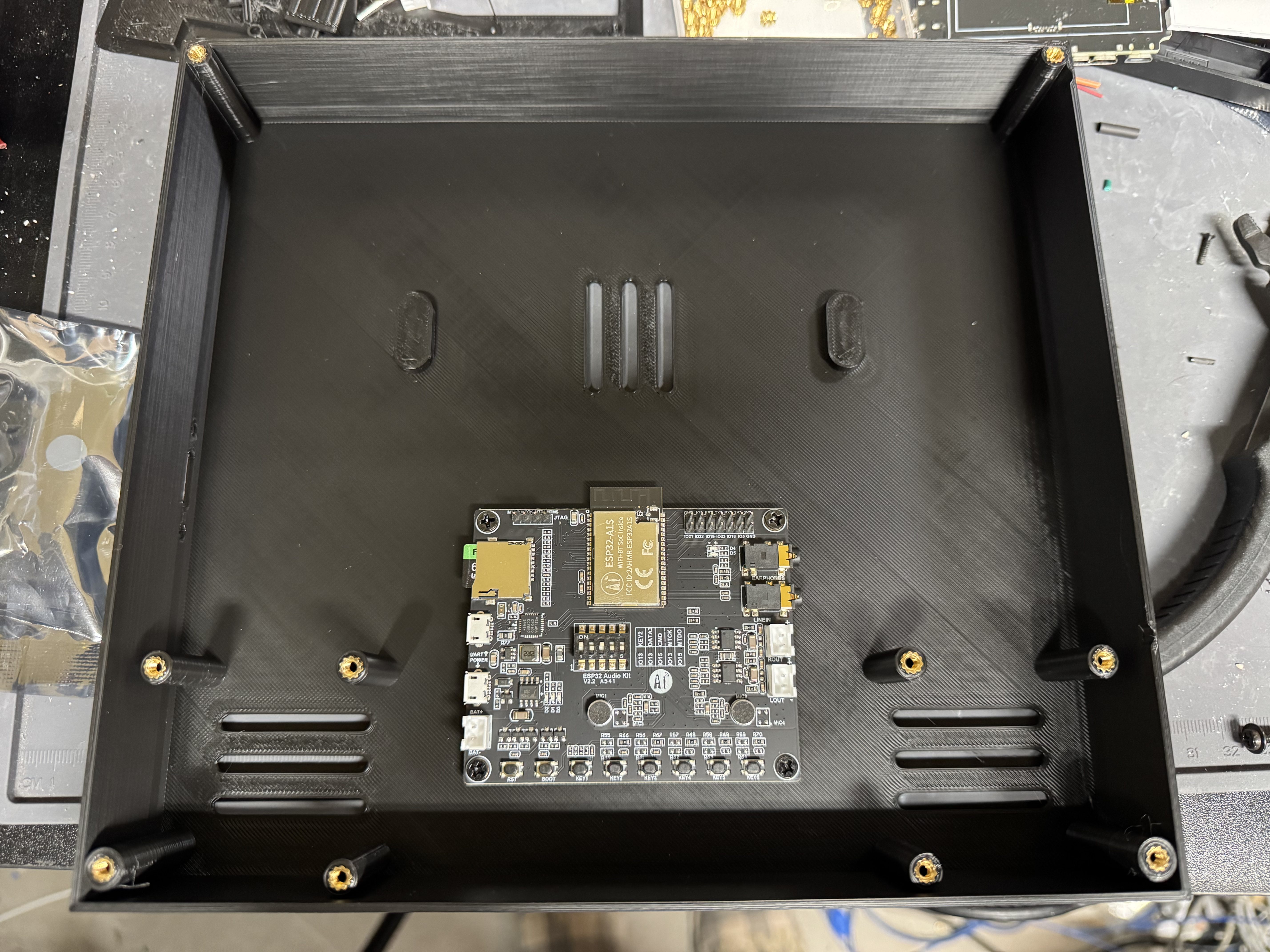
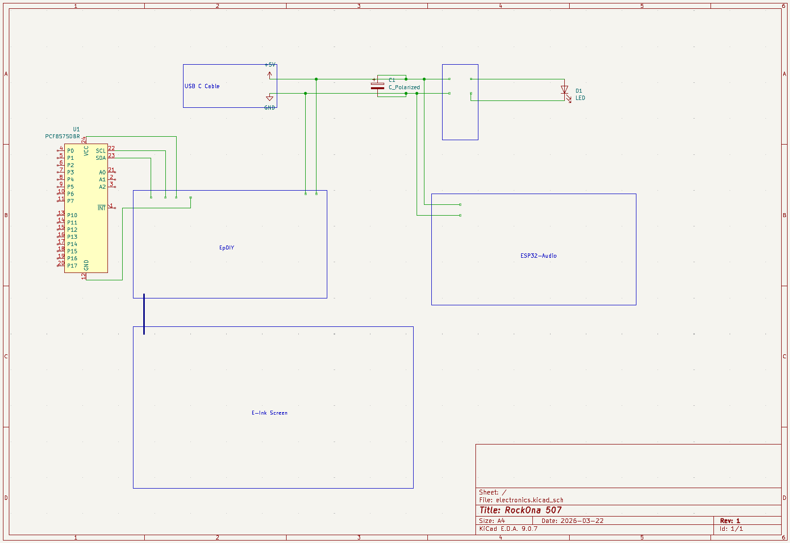
The EPDiy was great for handling the E-Ink screen and uses an ESP32 that I knew how to program for; the issue was it doesn’t have enough ports for everything I need, and I need something to drive the audio as well. I returned to the ESP32 Audio board I used in the History Phone project. As I said before, its documentation is bad, but I now know how it works… so the devil you know…
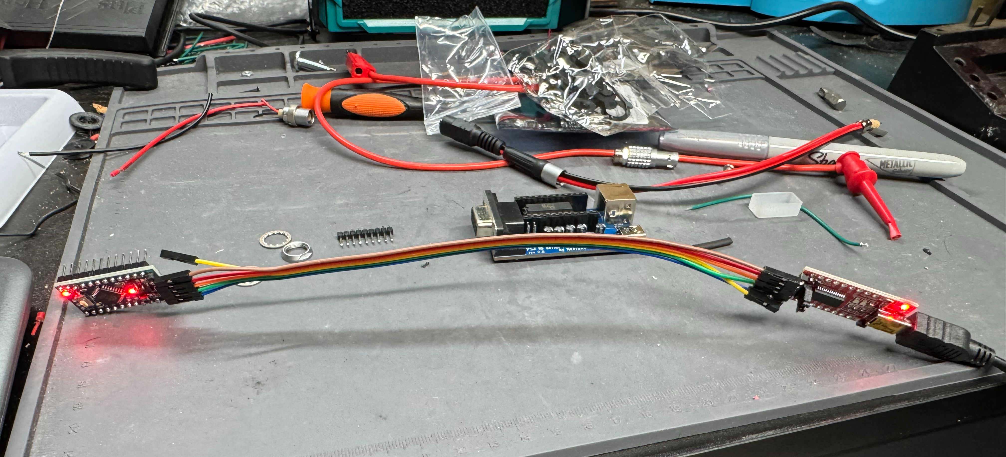
The idea was to connect these two controllers, EPDiy in charge of user input and output, I called this one the IO Board; then the audio board in charge of SD card full of music, organizing the music, and playback, I called this the jukebox board. They share a serial link. The audio board comes online, checks an index of audio on an SD card. Then after reading the table of contents, sends over what to display to the IO Board. The IO Board sends back button presses as they occur. I haven’t done a project with two ESP32s working together yet, but Claude helped me get the code set up.
Quick Rust Interlude: I was interested in trying to use Rust as the ESP32 controller language instead of C, except when I looked all the libraries that make the audio board work are C, and then the EPDiy libraries are C. I either would need to do a ton of inter-language linking, or I could just do the project in C; which I did instead. Also to use Rust, I couldn’t easily use Platformio which I have been using for ESP32 projects. Platformio allows you to use Visual Studio Code to build out your Arduino / ESP32 projects, and I like it much more than the Arduino IDE or other command line tools.
This was a project I was playing with Claude Code to throw together some of the C. The code is straight forward, and Claude put together a python script which let me manage the songs I was loading on the SD card, setting up the metadata correctly for the audio board to parse. I also was able to add Bluetooth audio support. I set one of the song selections to a special setting, and that puts the device into Bluetooth pairing mode! Once a song is selected, that mode disables itself.
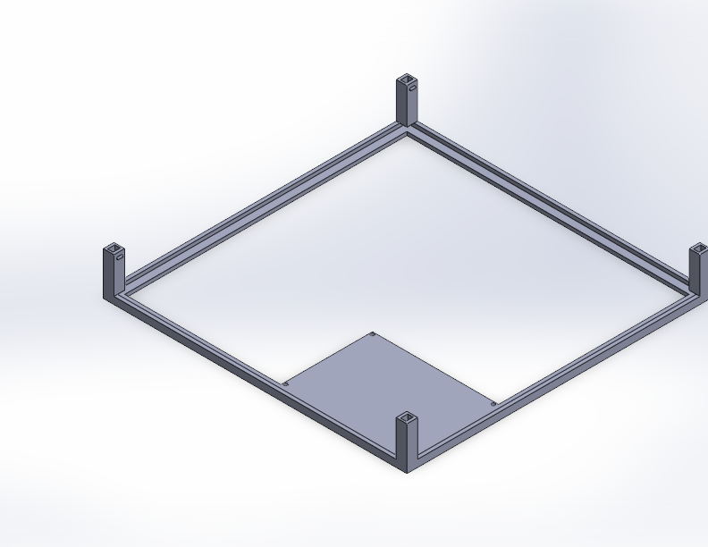
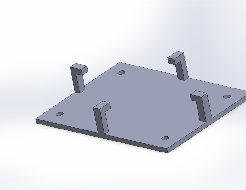
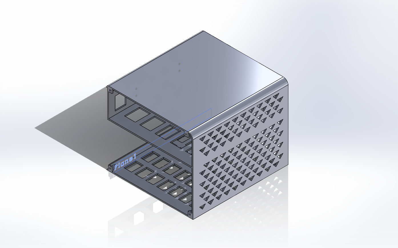
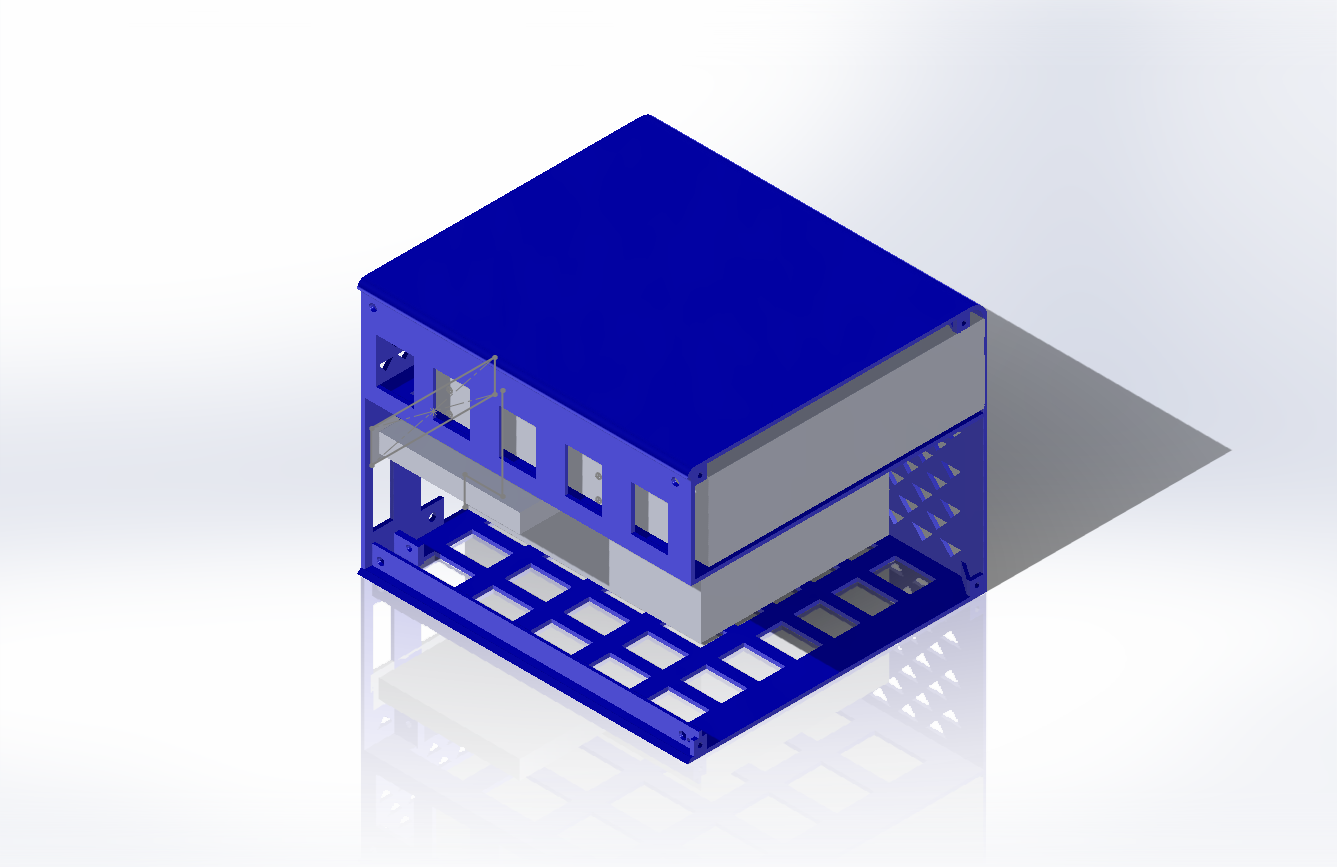
3D Model
I have been trying several different 3D modeling systems recently. For years now I have used Solidworks, and it works well other than it’s a giant Windows app that periodically gets hours of patching done to it. I tried OnShape, a web-based 3D modeling tool, after I ran into someone from the company and they recommended it. You get to use all their standard tools for free, as long as your designs are public. I gave it a spin. It worked decently well. My normal keyboard shortcuts didn’t all work, but that is from years of using Solidworks, not their fault. The main issue I kept having was the mating system. Theirs is MUCH different from what I am used to (again from years of Solidworks) and I kept stumbling.
This holiday season Solidworks for hobbyists was on sale, including the standard Desktop version AND the web version. I had to pay twice but got a year of each for the normal $49 price. I want to love the web version. My models aren’t that complex, and honestly Solidworks is one of the last things that keeps my desktop computer on Windows. I will keep experimenting with it, but I did find it slower and more cumbersome than the desktop version of Solidworks. In the end I made an early render in each but did the majority of the work in Solidworks Professional, the desktop version.
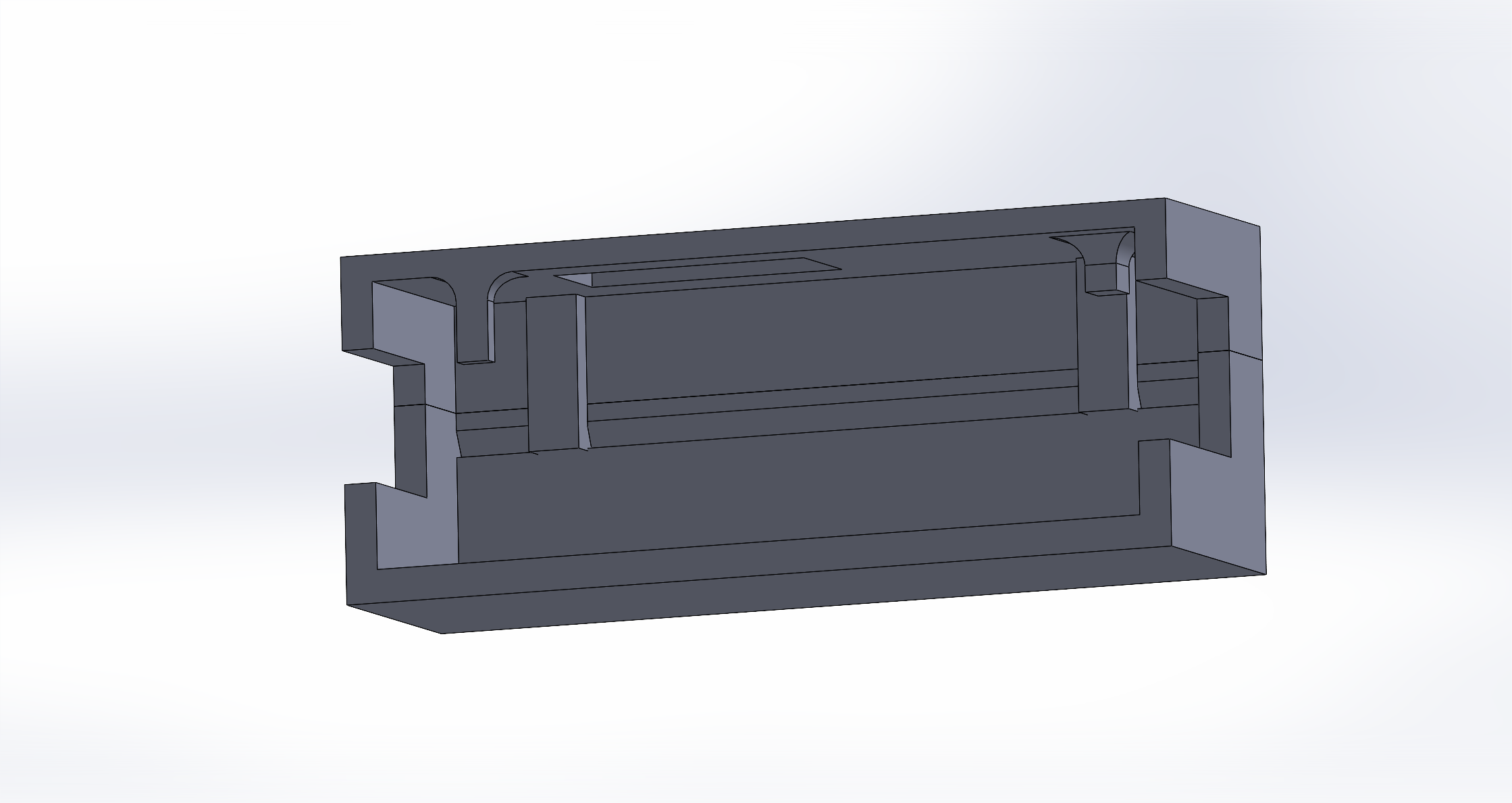
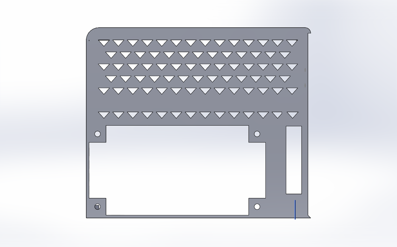
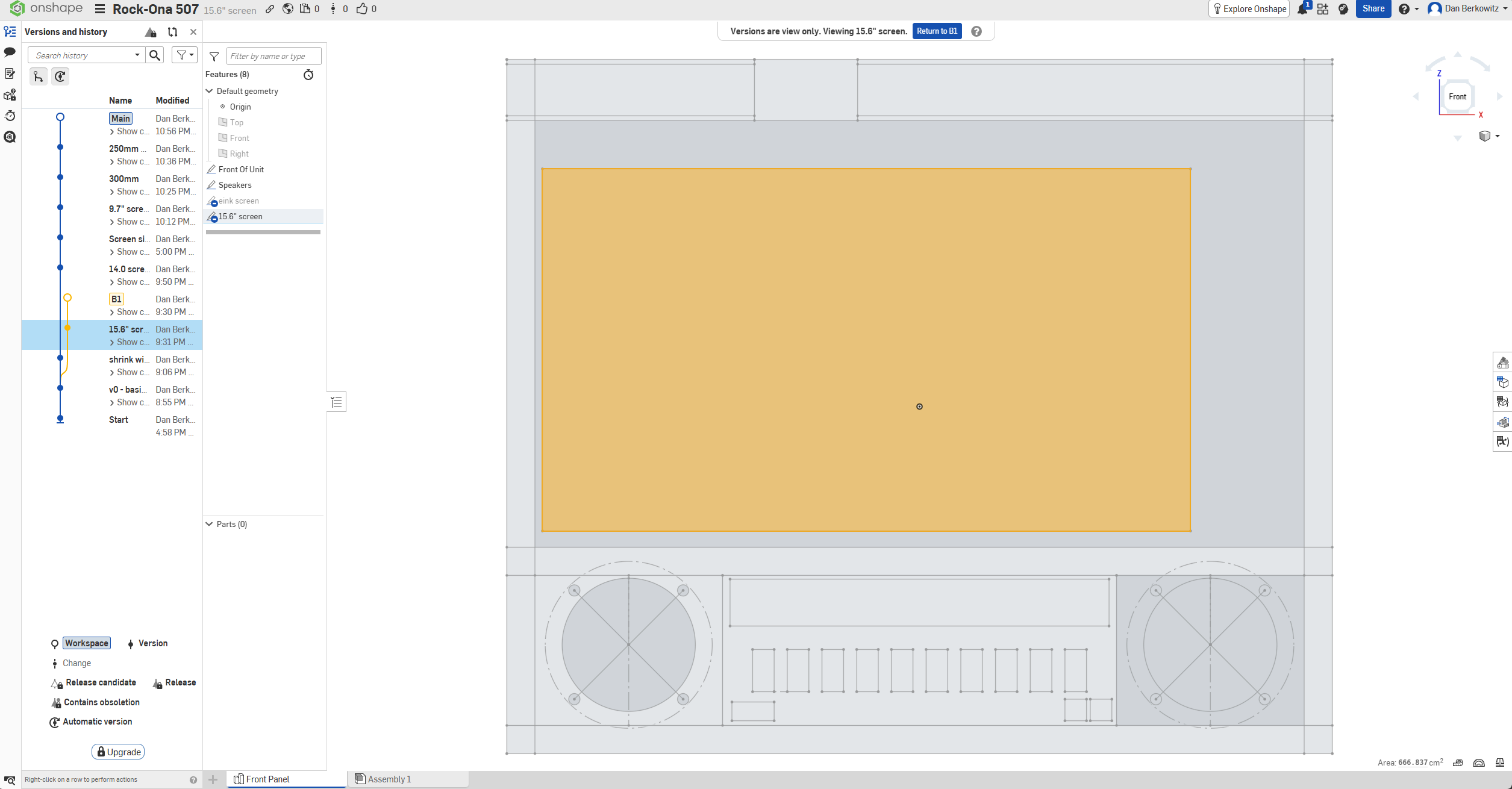
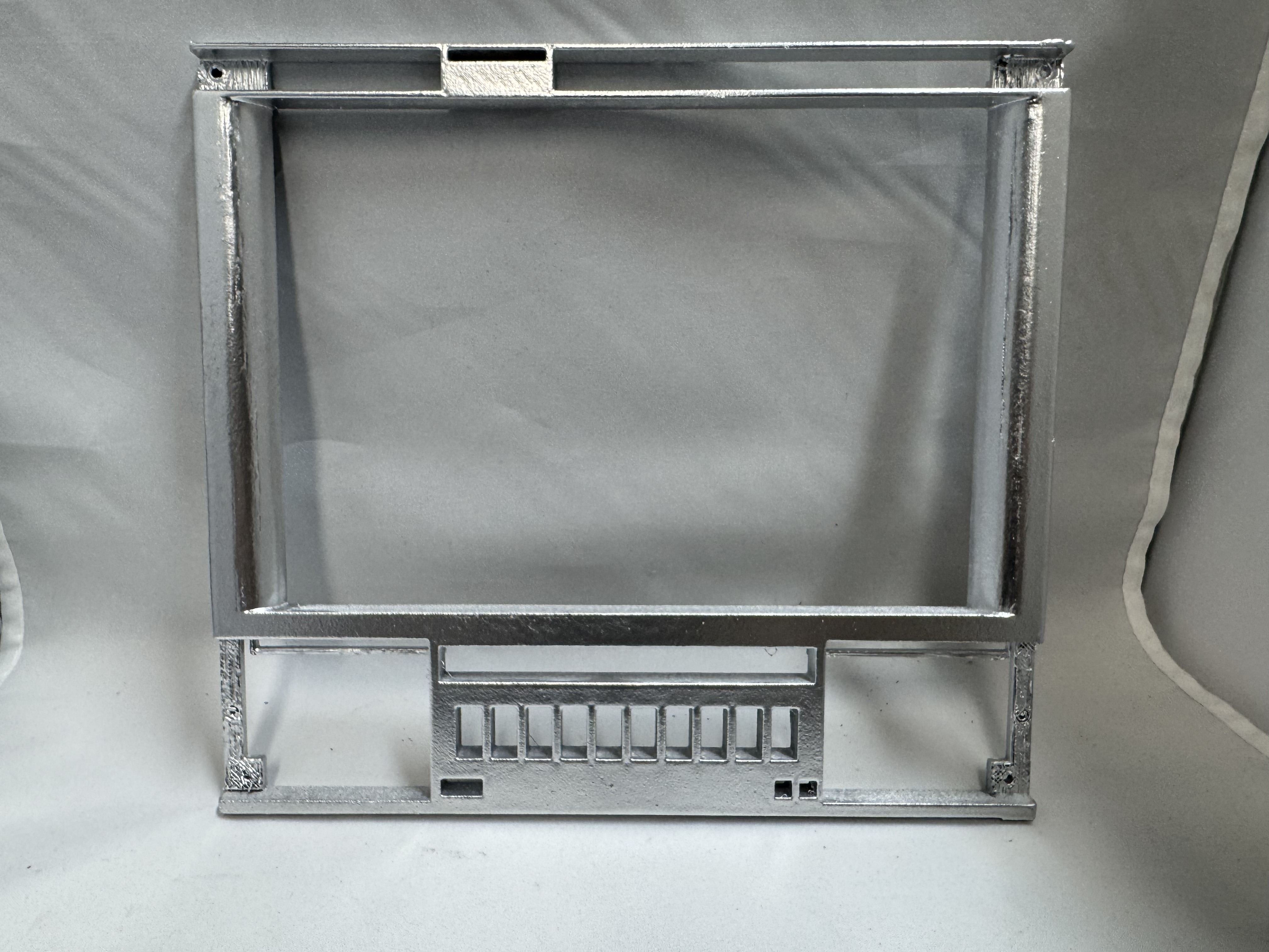
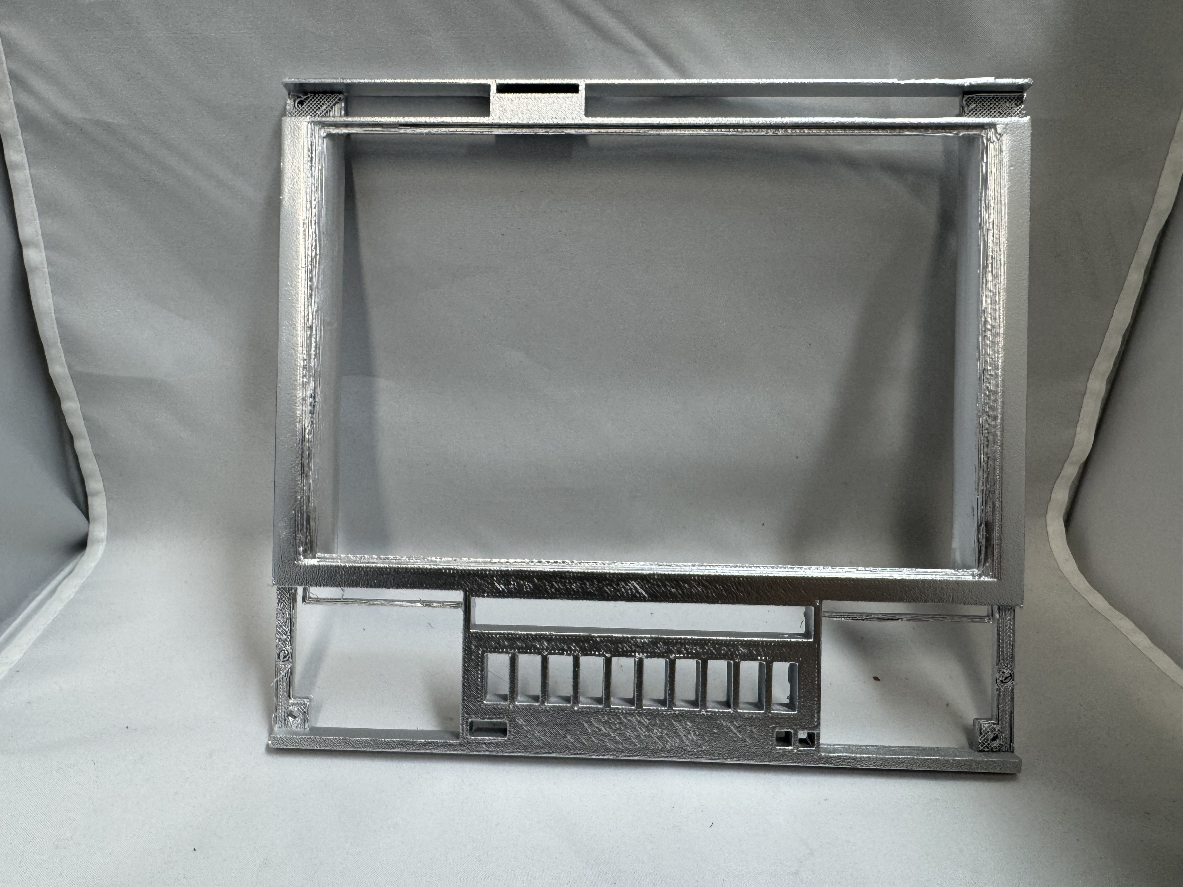
The original version of the Rock-Ola 507 was large, larger than a photo may let on. It was 18 inches wide, by 15 inches tall, and 6 inches deep. It was also 30 pounds… It was BIG. Here is a screenshot of OnShape with a 15.6″ screen put into a version where I had already shrunk down 2 inches.
Quick aside: One neat feature of OnShape is git-like versioning of your models. You can see on the left I tried different sizes and different screen ideas.
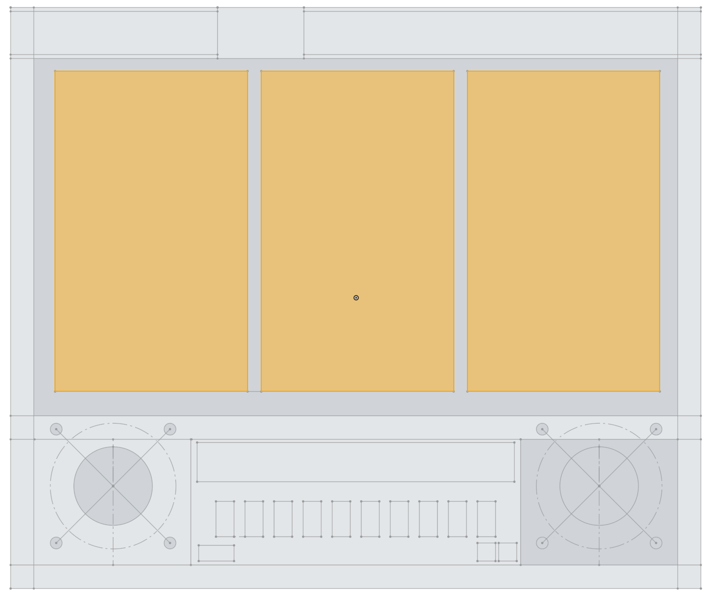
Here was another attempt at fitting different screens, this time I had 3 x 7.5″ (kindle like) screens in the device. Still way too big and would require 3 EPDiy boards working together (I did get 4 in case I went that route) greatly increasing the cost. This would be good for hanging in a garage or basement, but I wanted something a bit more compact.
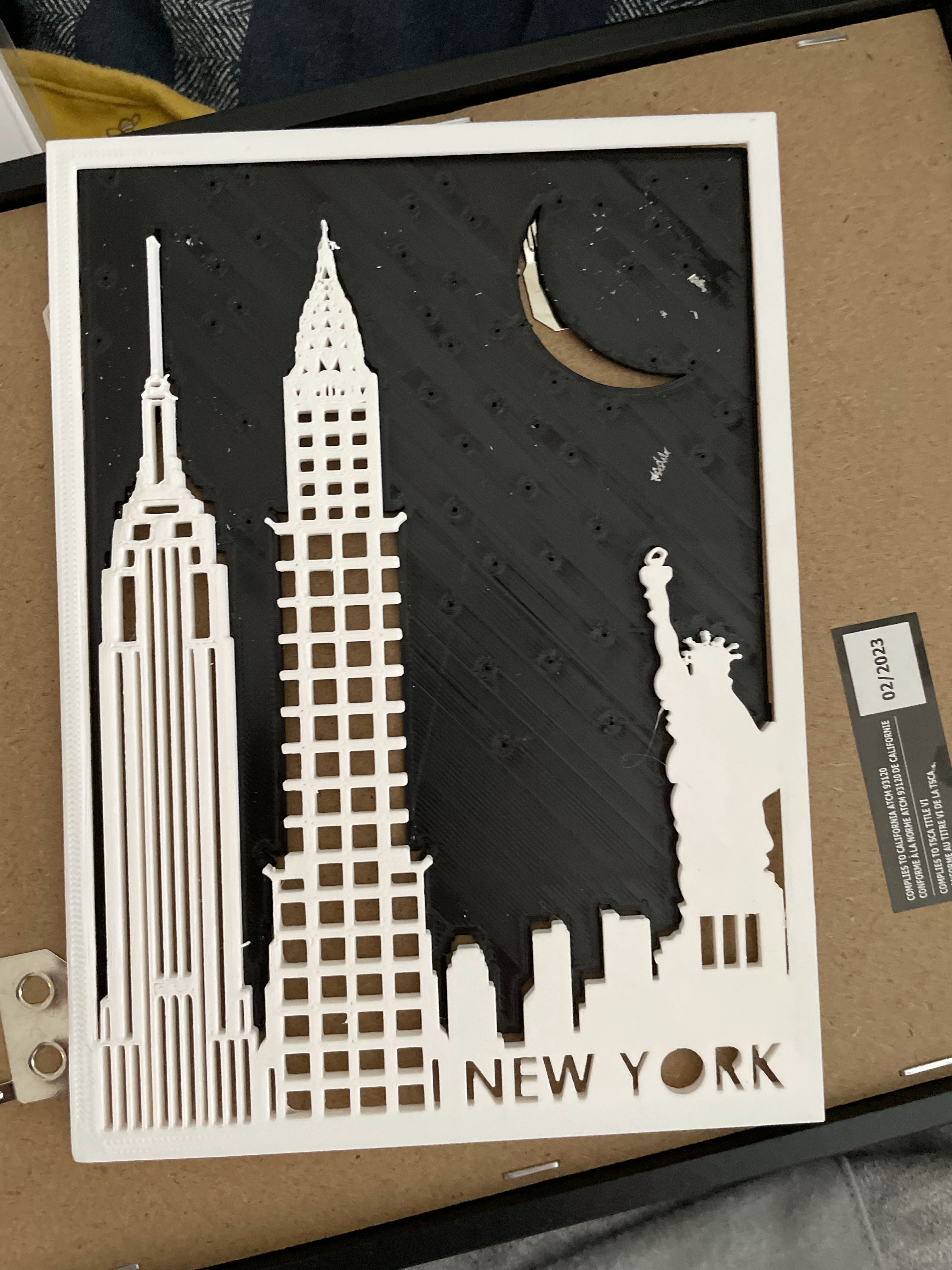
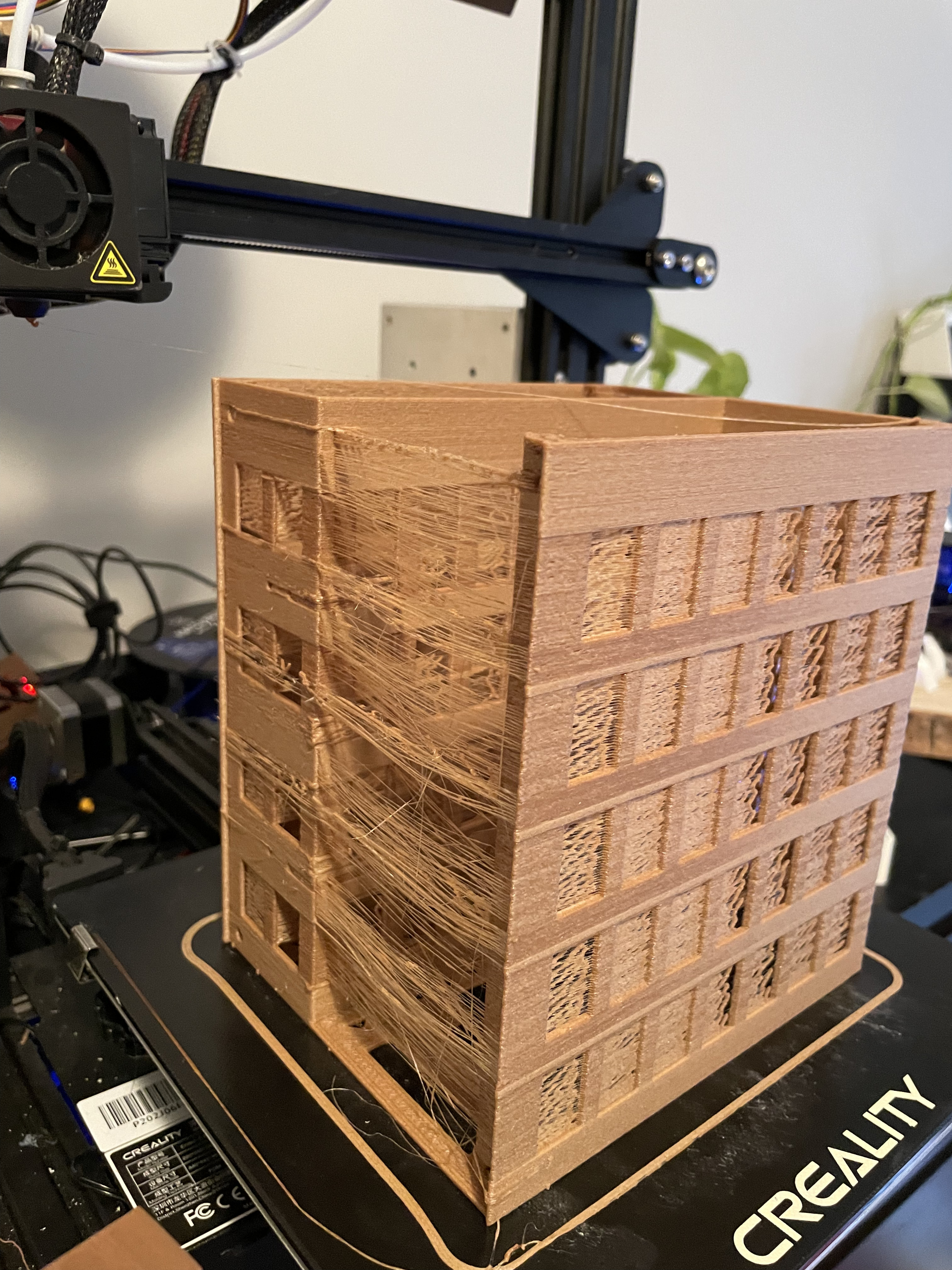
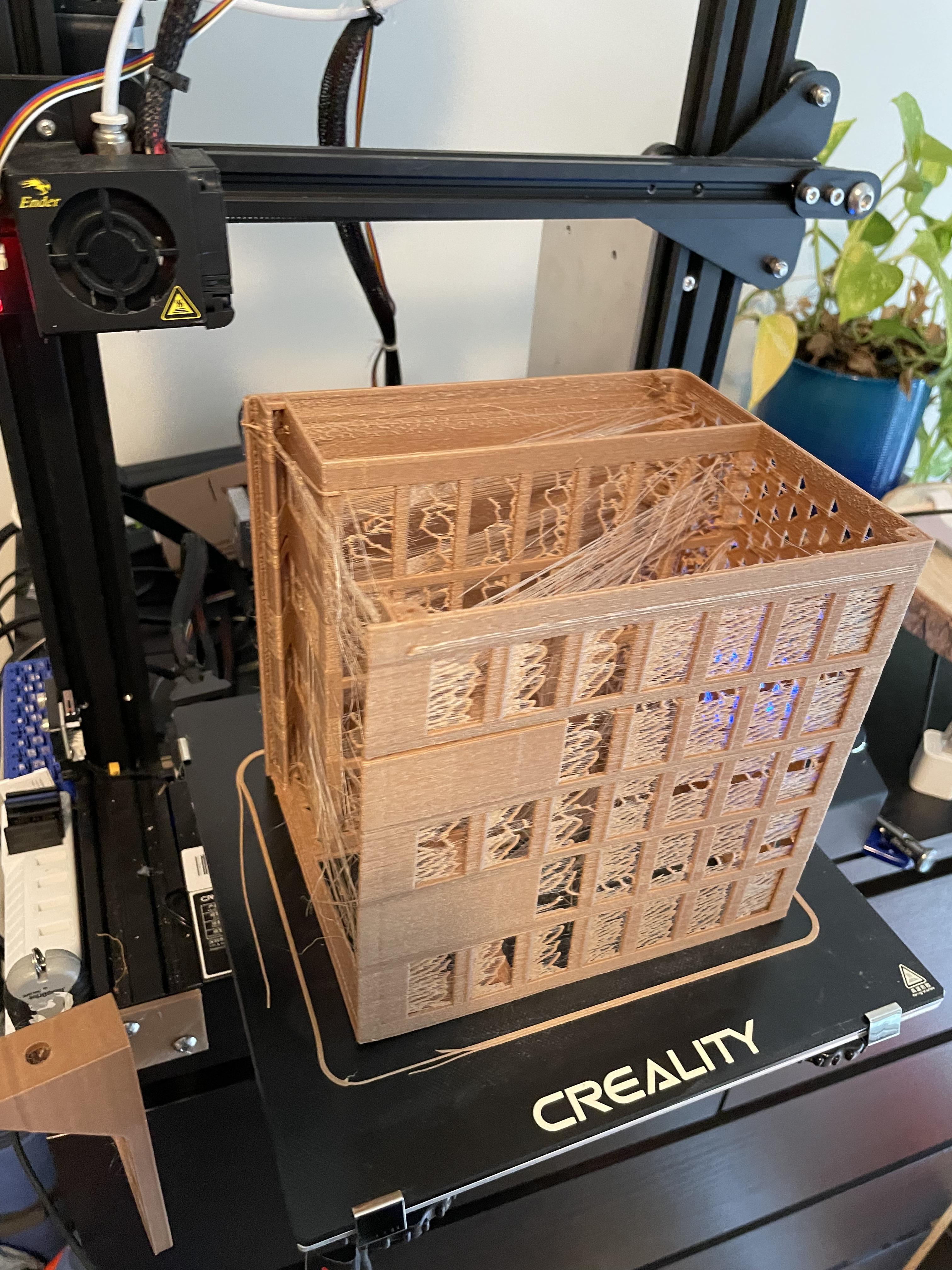
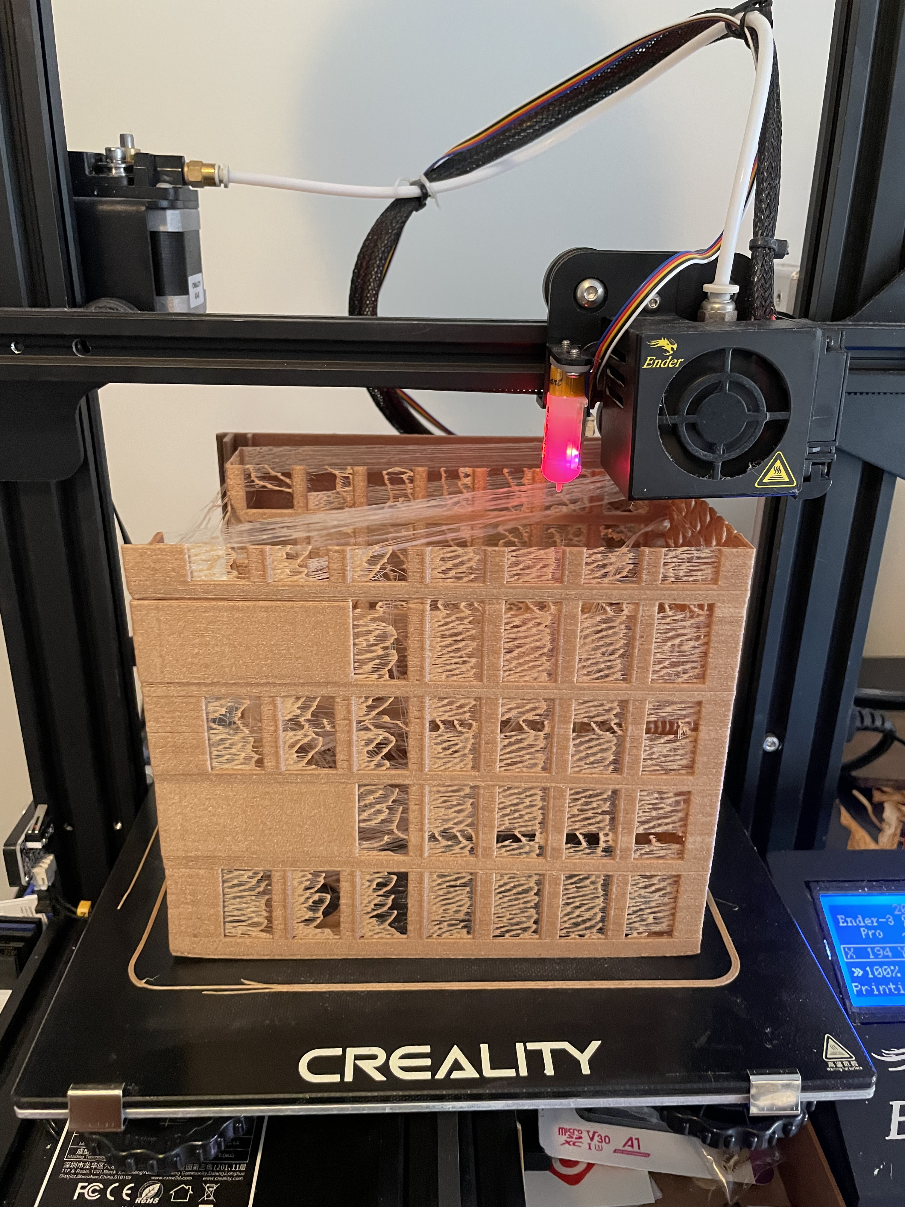
I ended up shrinking the whole thing to ~9 inch across, about 50% the original one. This also allowed me to easily fit in on my 3D printer in one piece. I got a Sovol SV08 a bit ago, its 350mm by 350mm print bed made easy work of this.
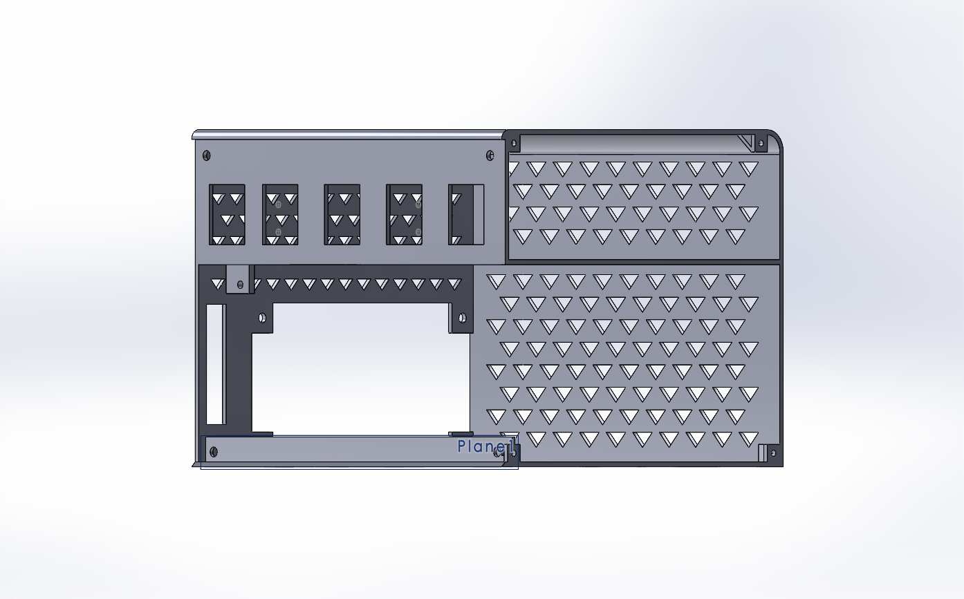
This is a closer to finished Solidworks model. I am not showing the screen. I had an idea of using cloth for the speakers to give it a more warm feeling. I did try this on the first unit I made of two, sewing is not my thing.
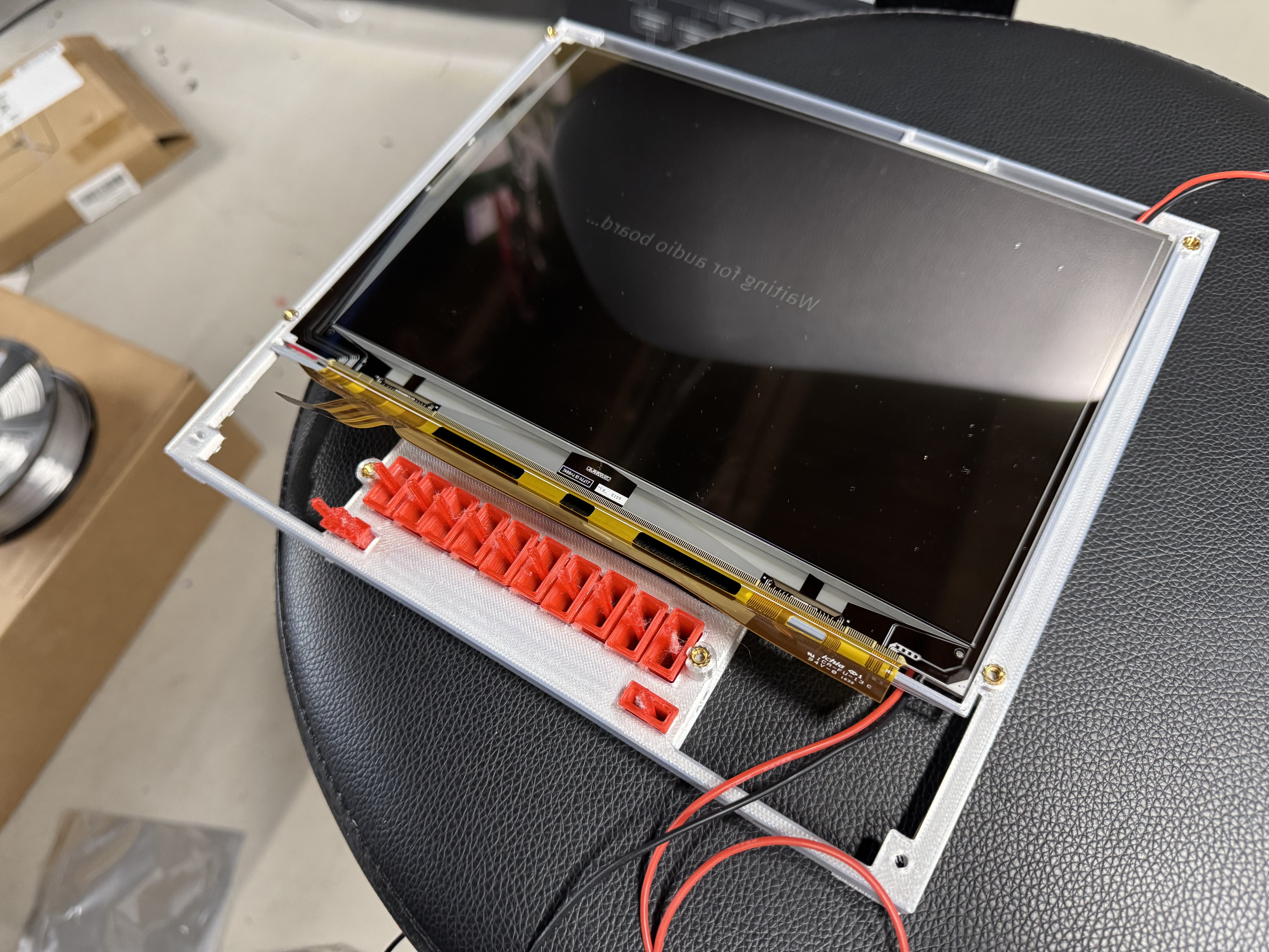
I got a 9.7″ E-Ink screen off amazon, that turned out to be around the same price I saw at places like eBay and could come quickly. At $68.99, this was the largest expense of the project for one item.
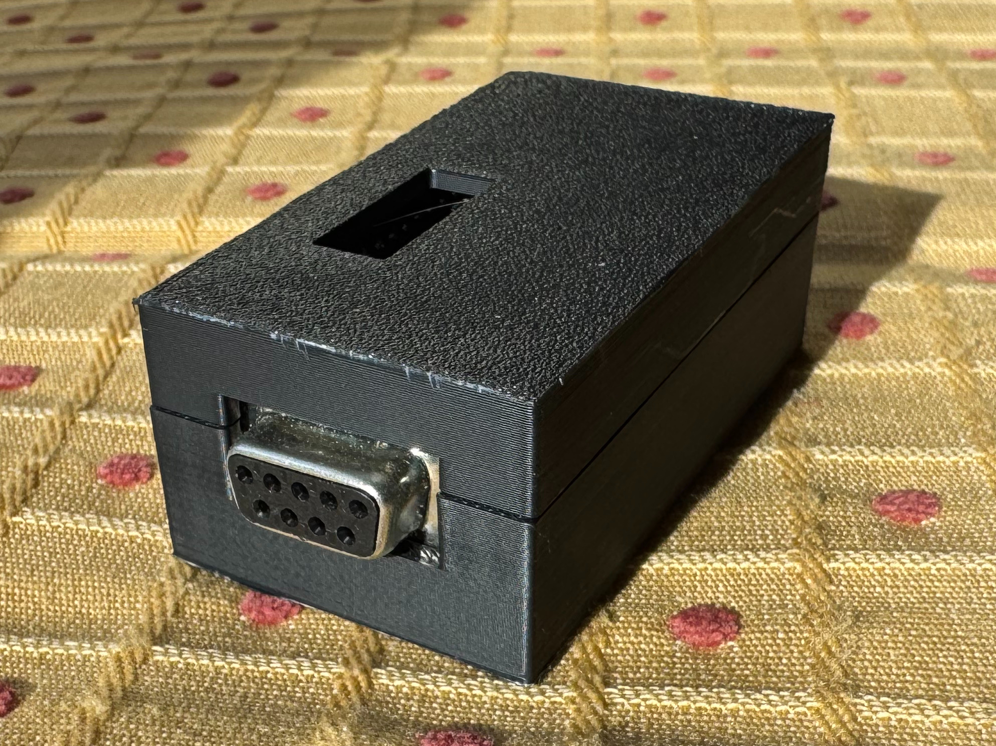
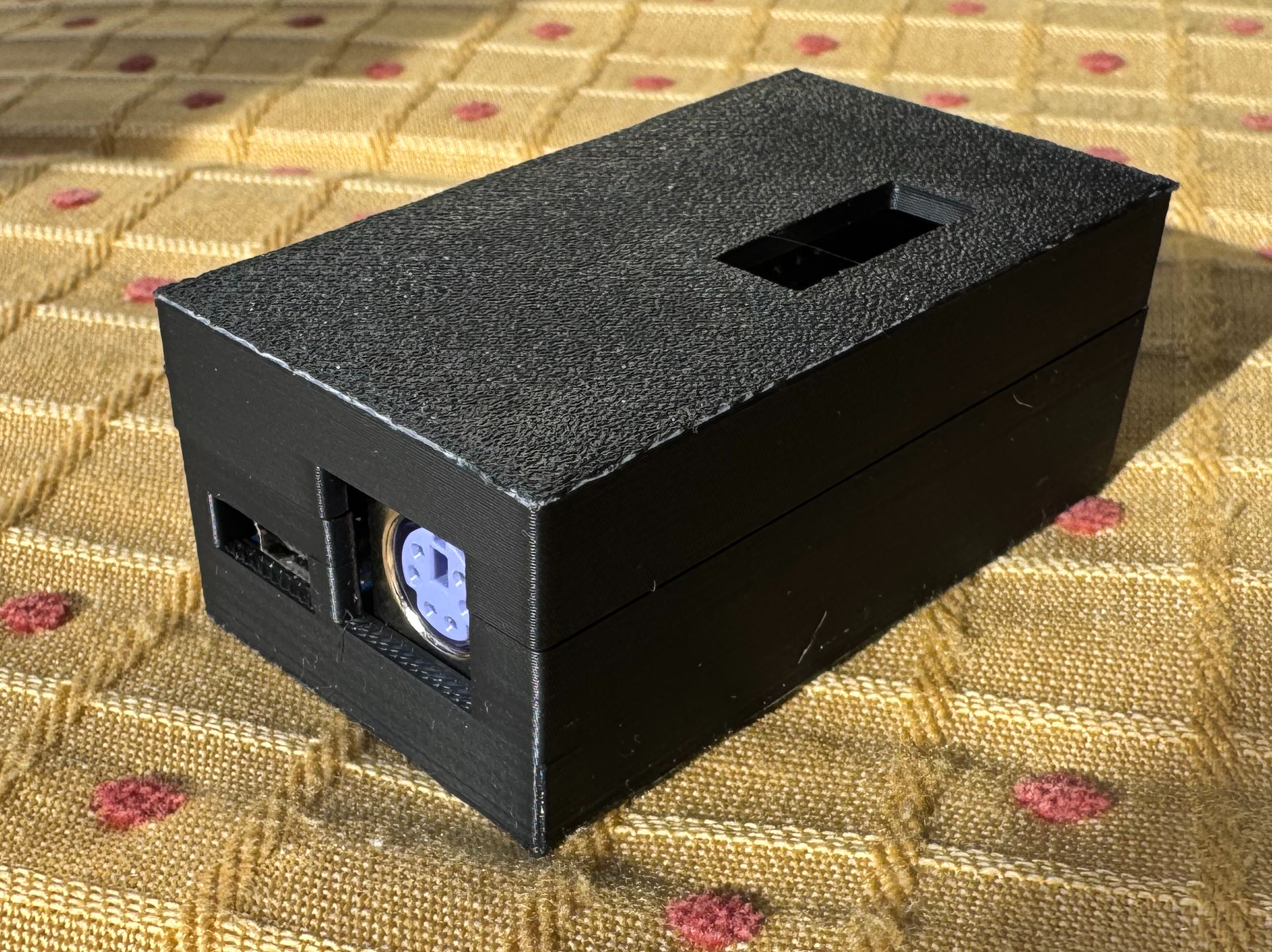
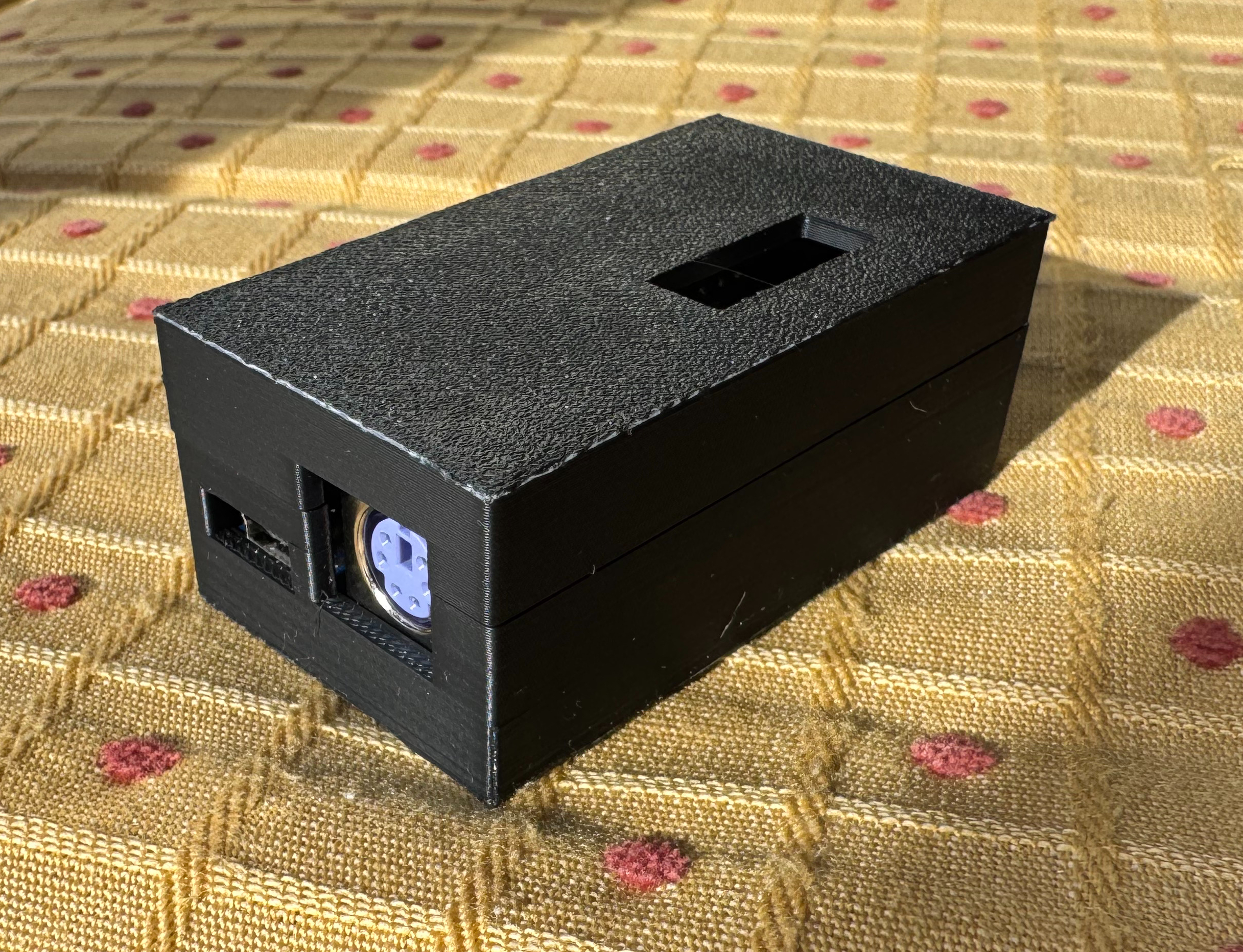
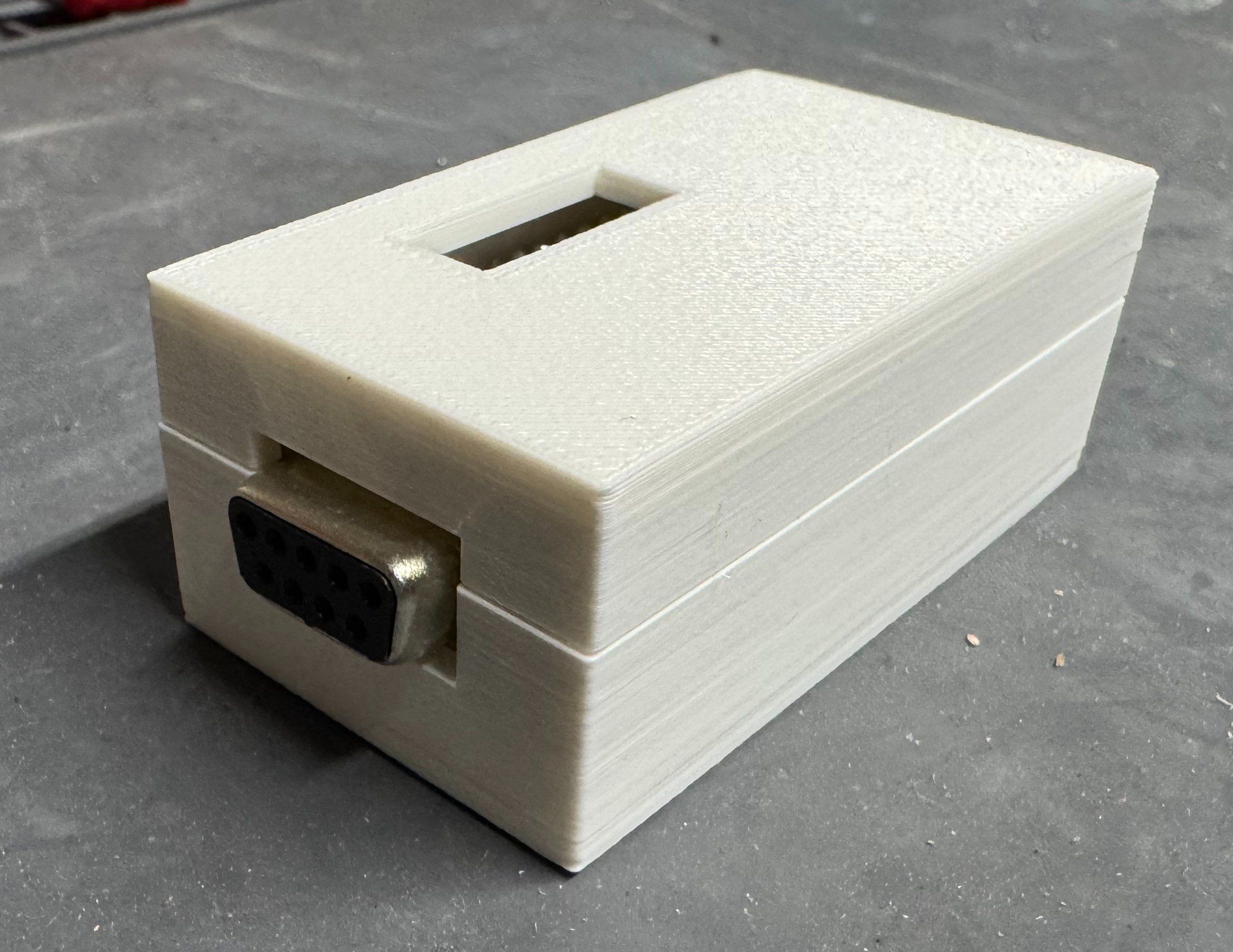
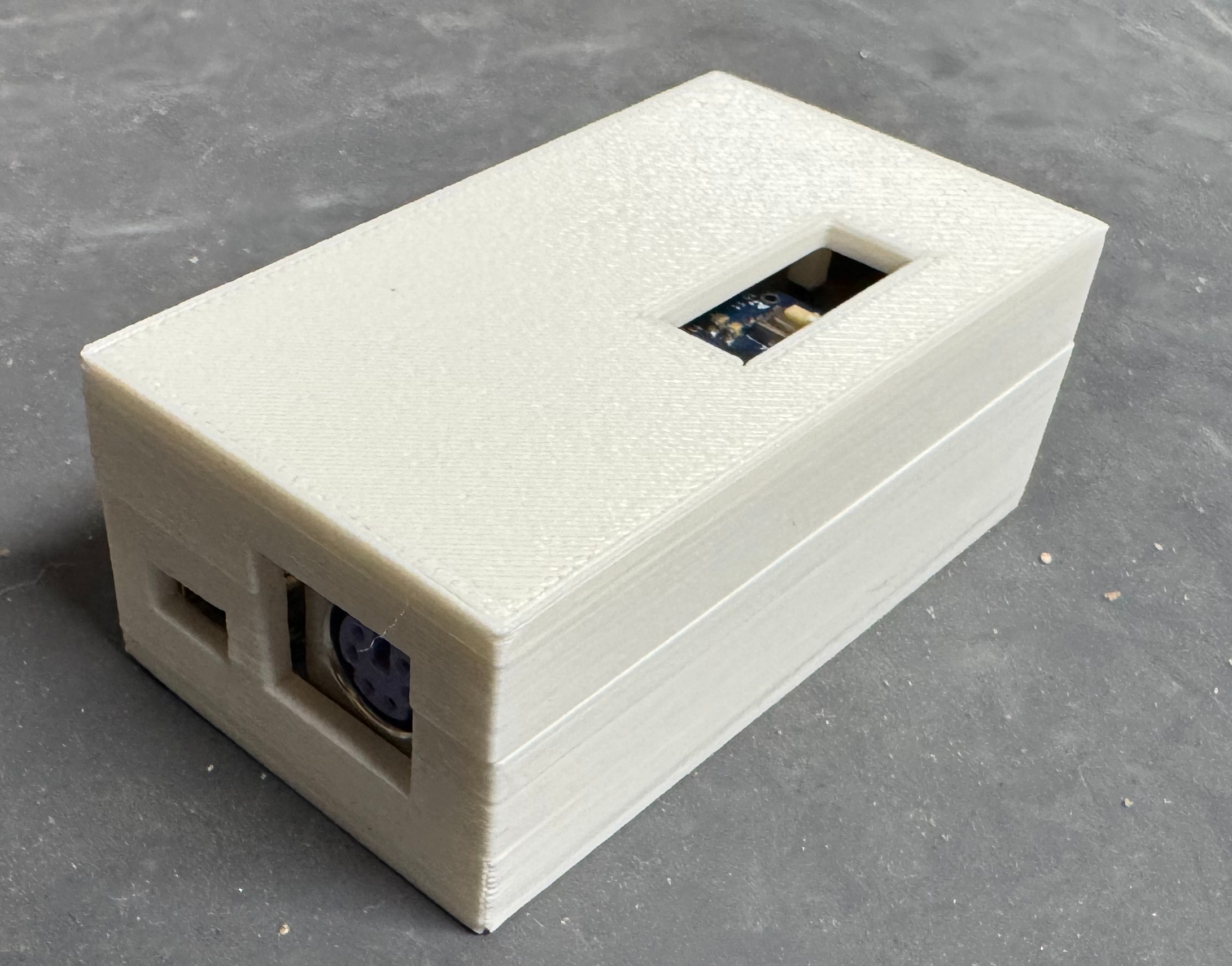
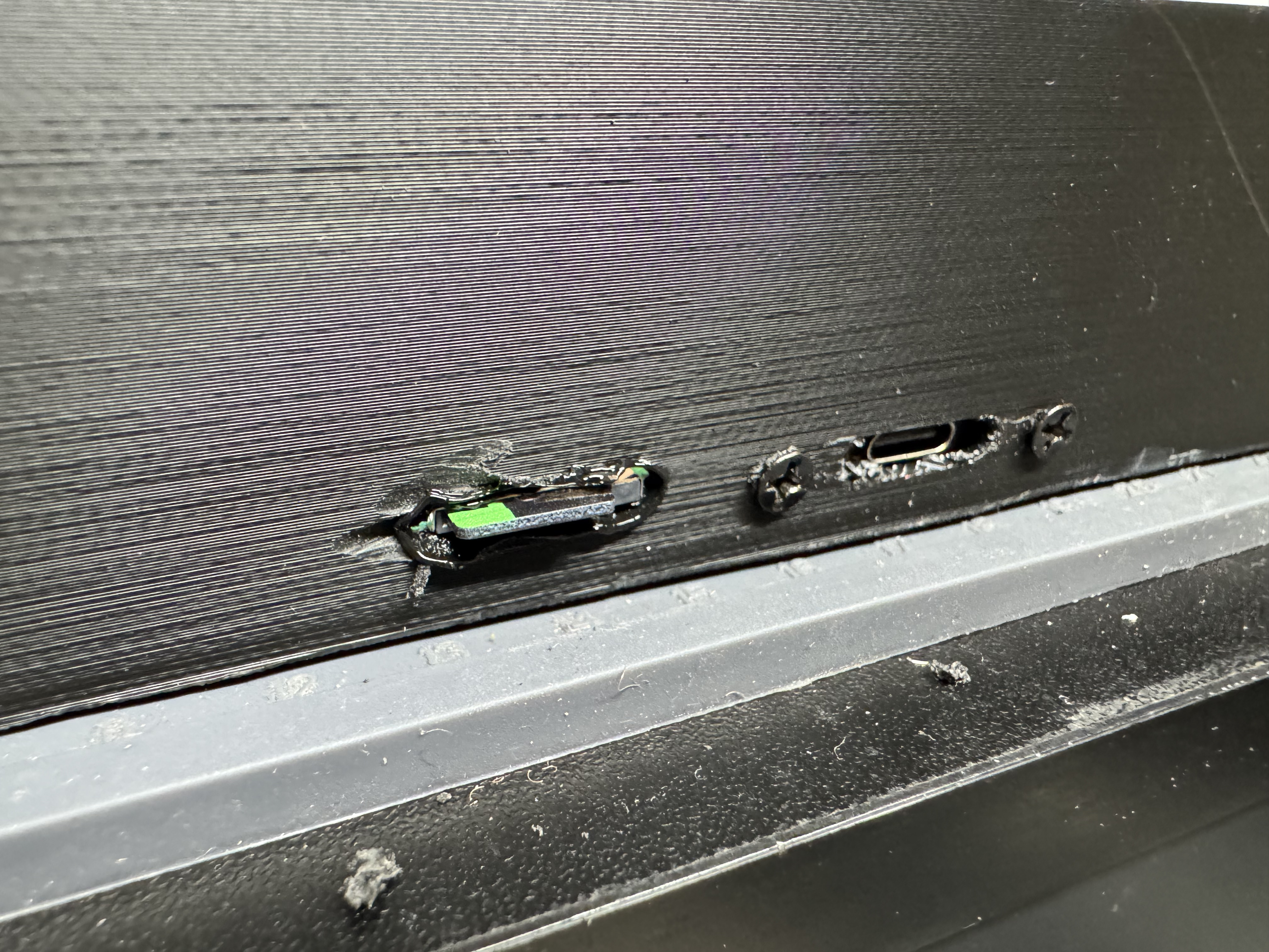
Much later I realized I had one place for the USB C power to go into the side of the case, but I didn’t have anywhere for the SD card. This would mean I had to open the unit every time I wanted to change the songs on it. I got a SD card extension cable, and already had a Dremel… so I made another hole in the side…
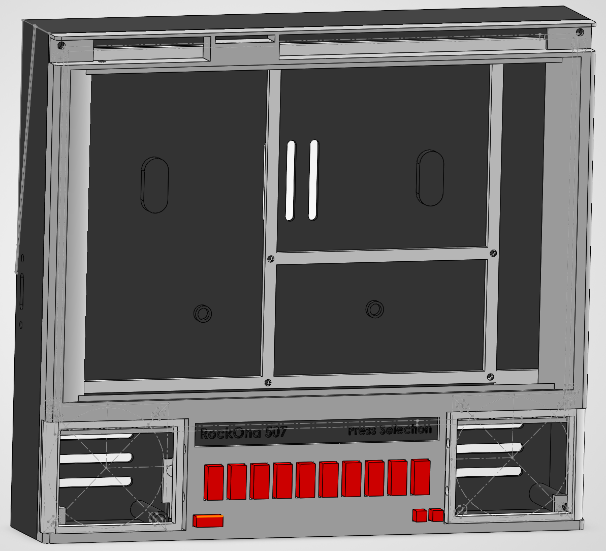
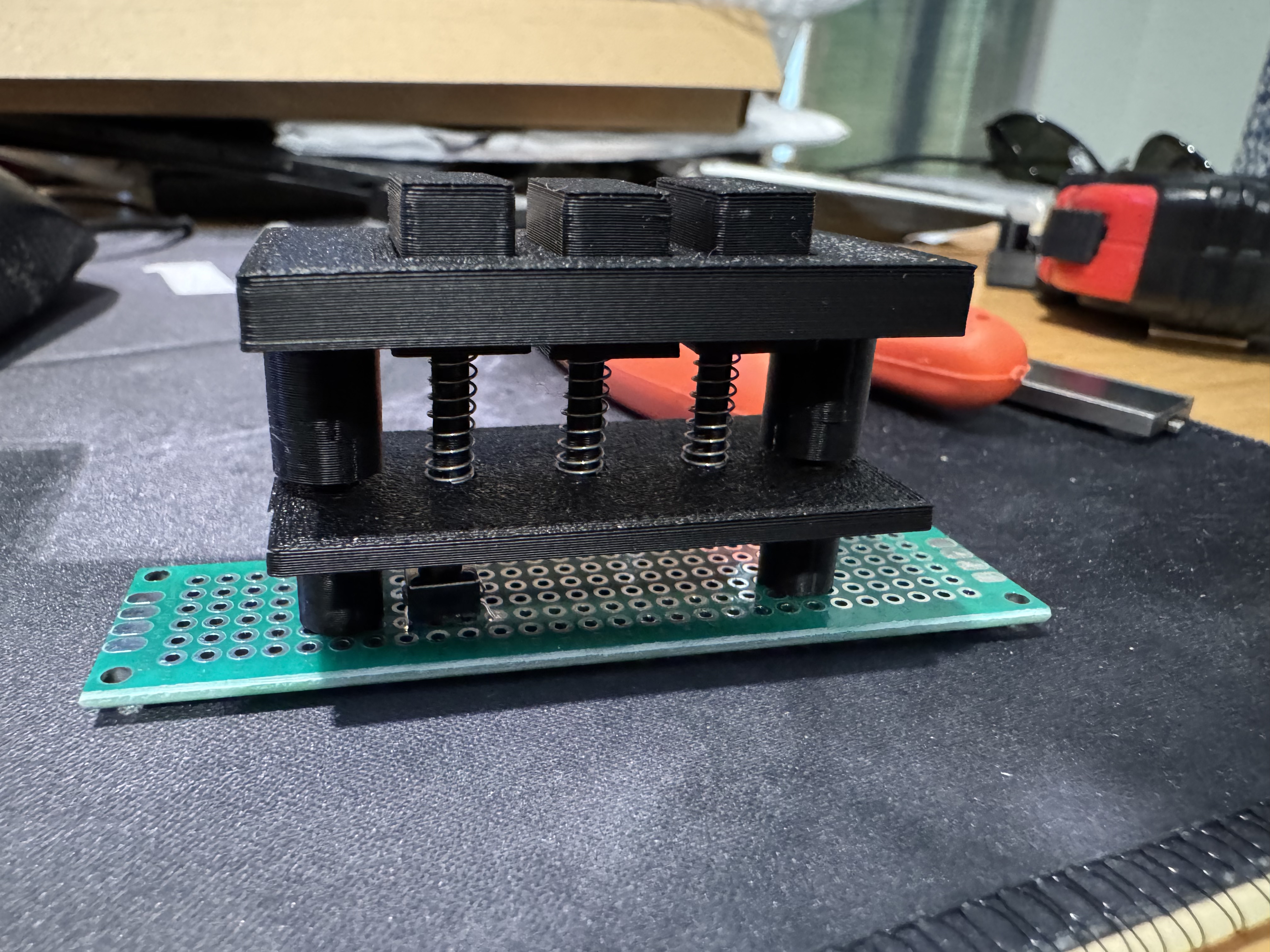
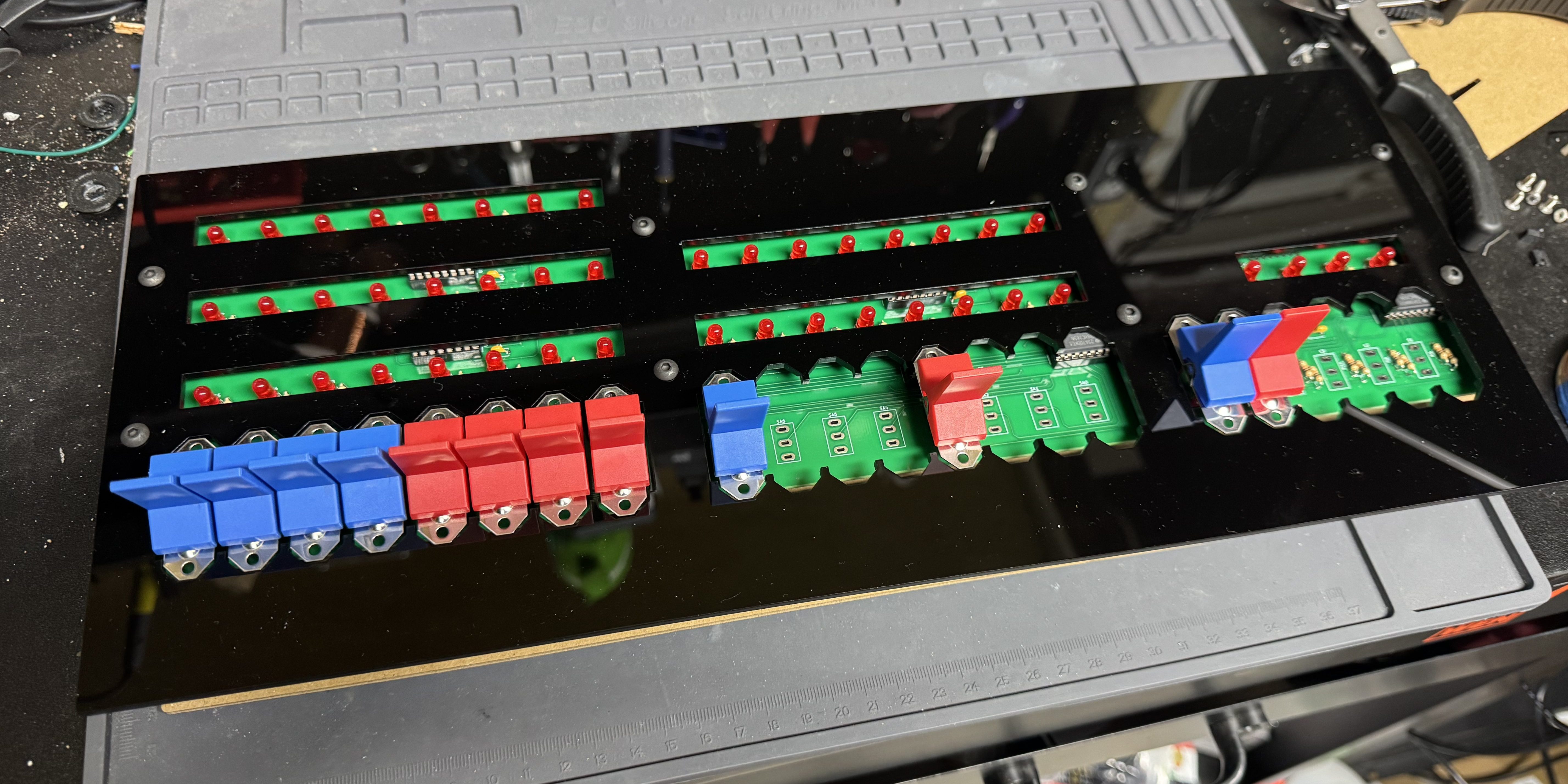
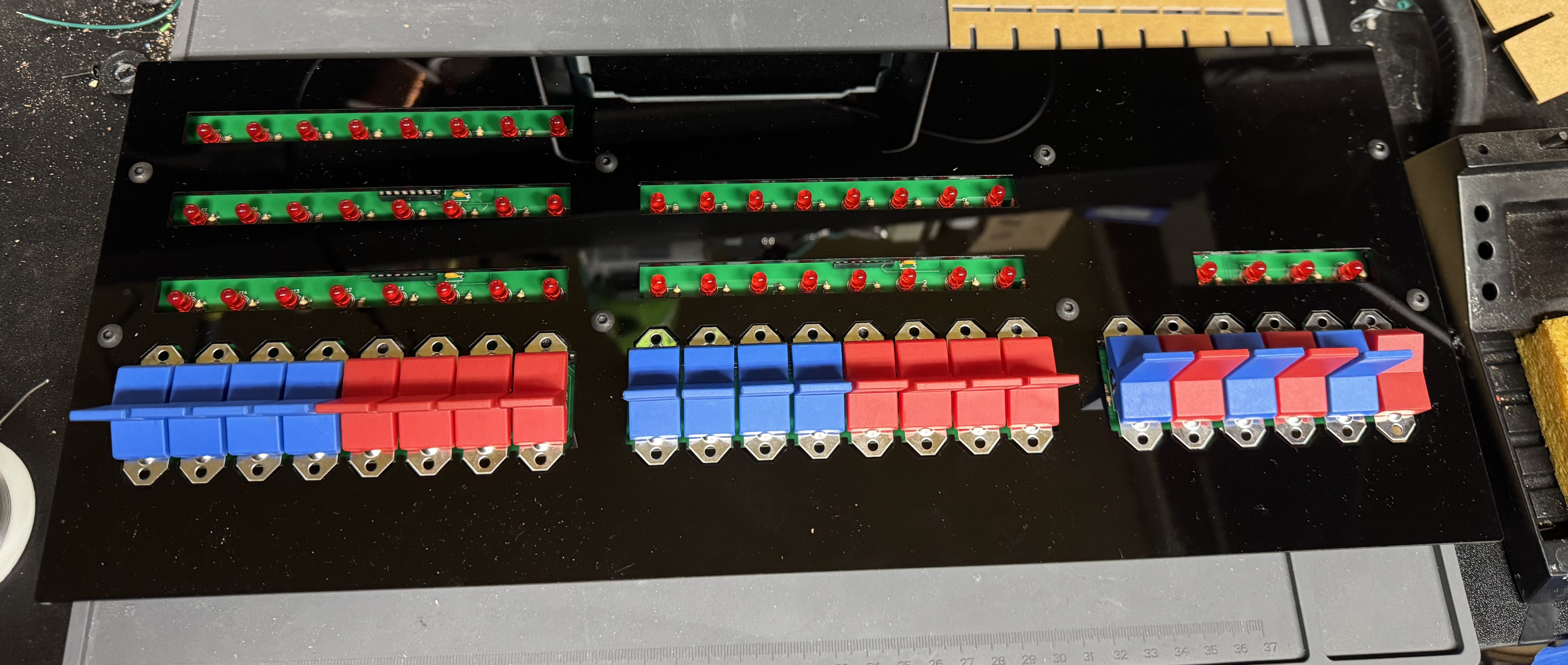
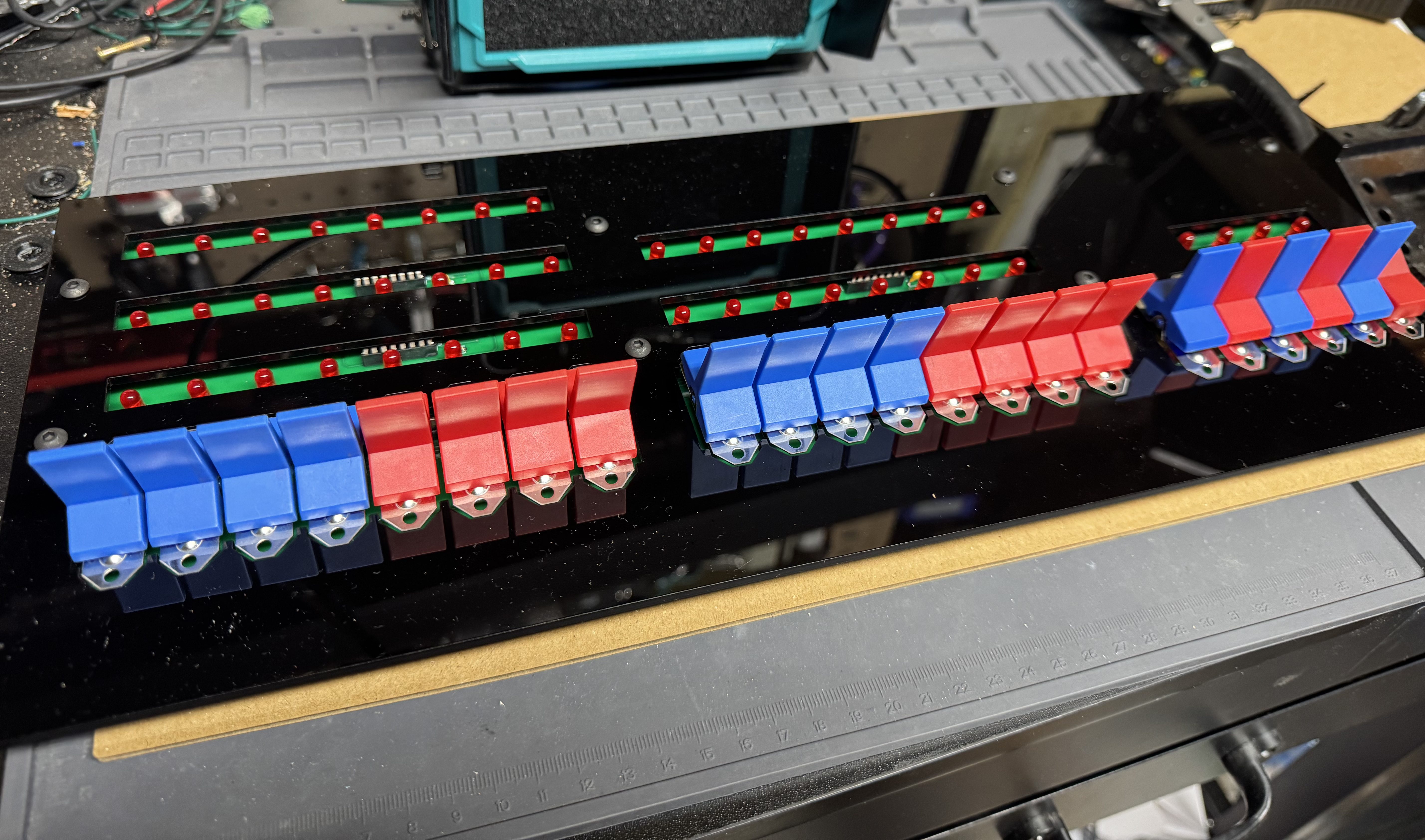
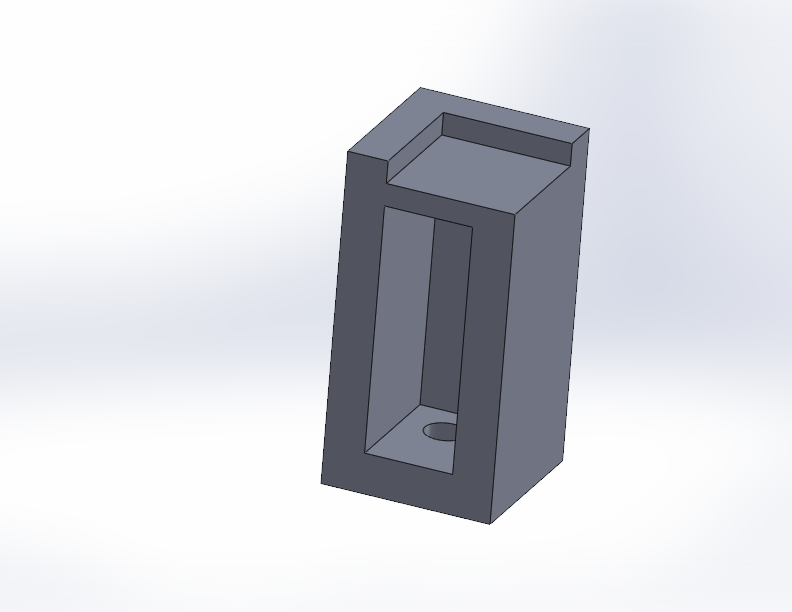
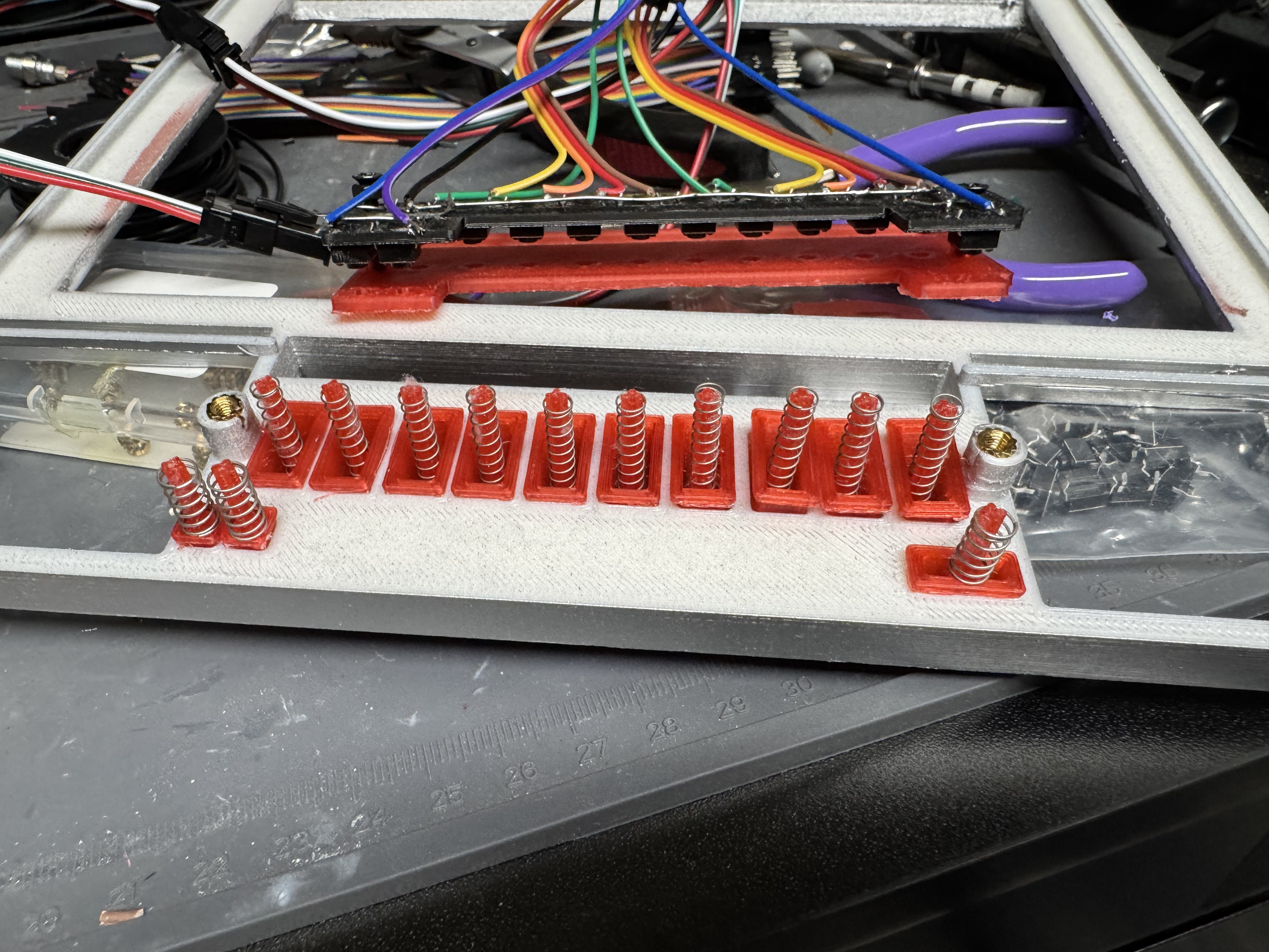
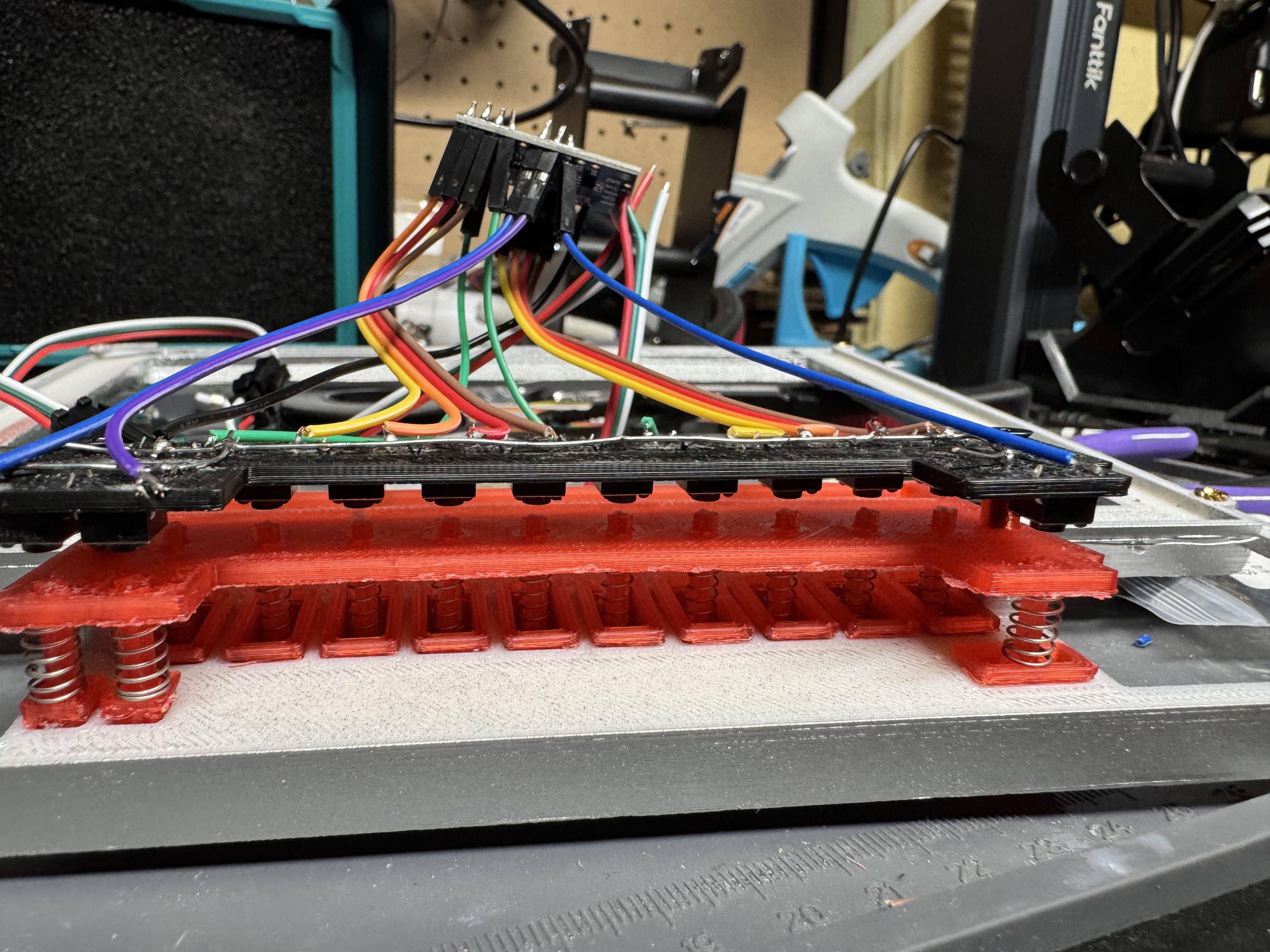
Part of this build was figuring out a way to make the buttons feel nice. I tried several iterations and different designs. I wanted a longer throw, but something electrically simple, and could fit in the case.
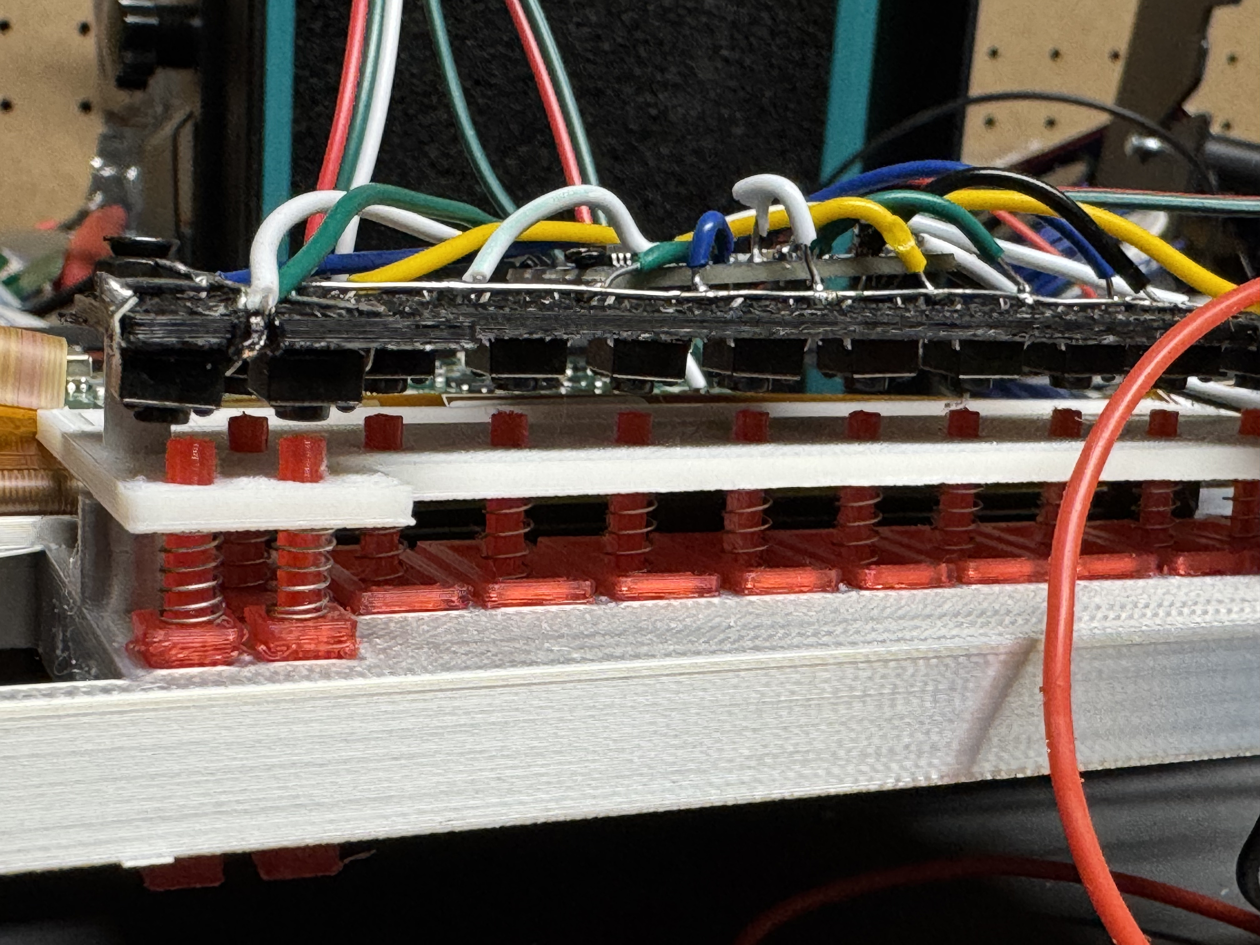
I ended up with this 3-layer design. Big button with a stem, that goes through a guide that has a spring, that clicks a little push button. You get the nice throw of the switch, a good click, then it bounces back.
Part Selection
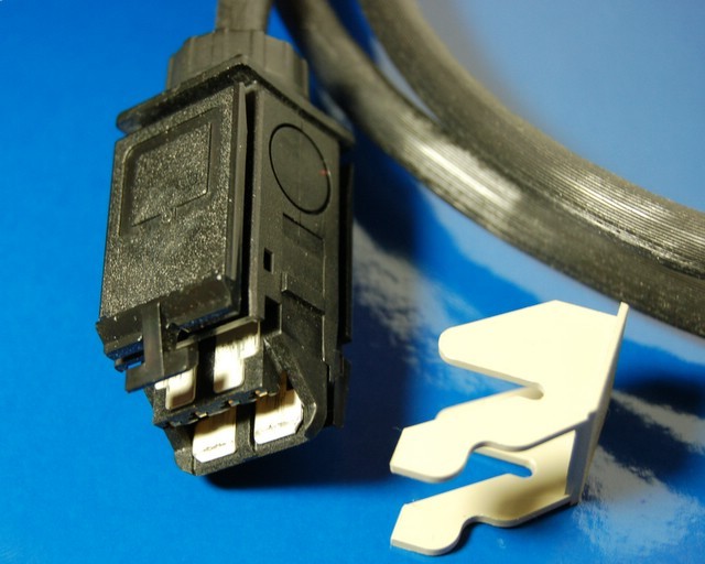
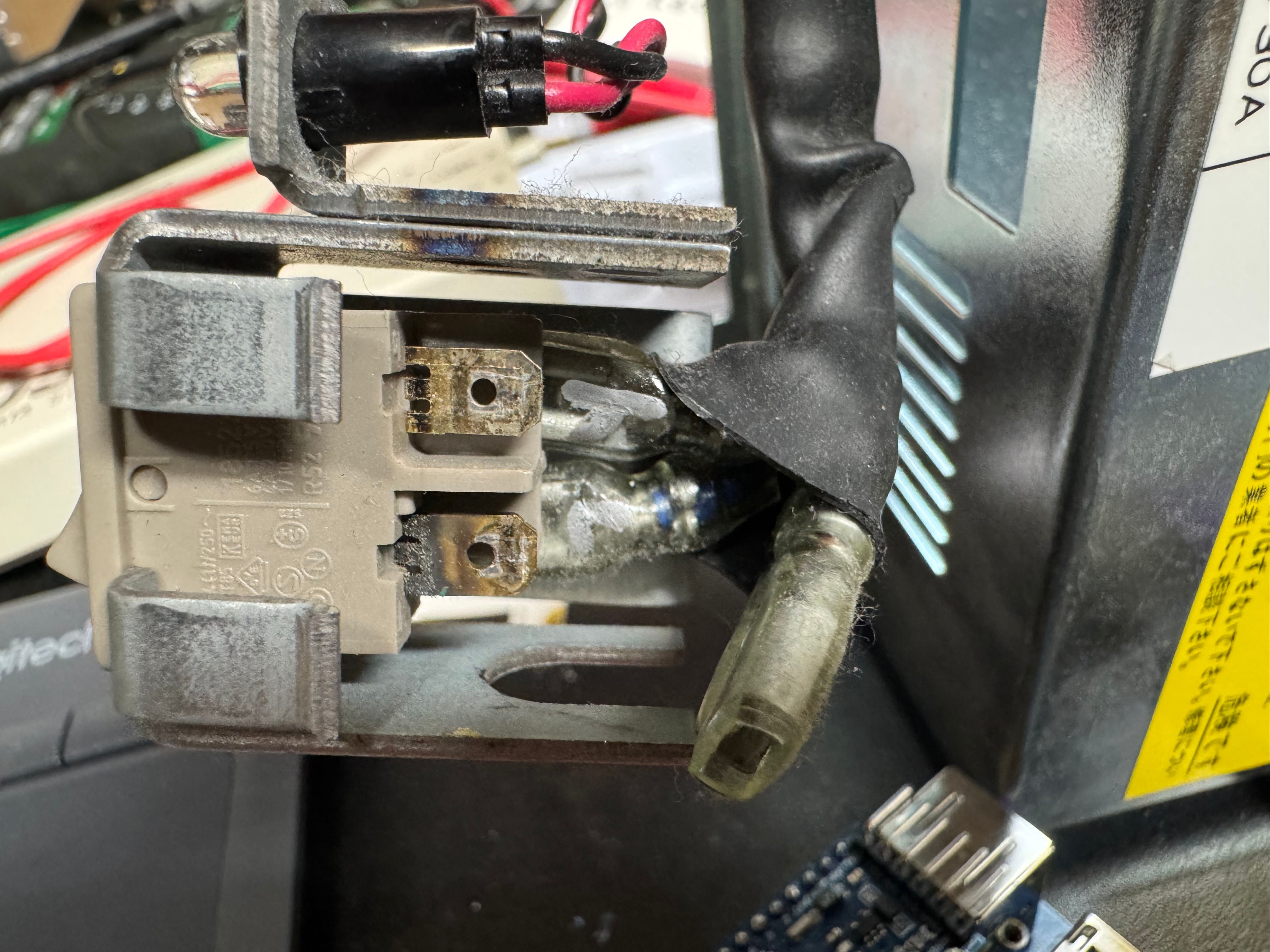
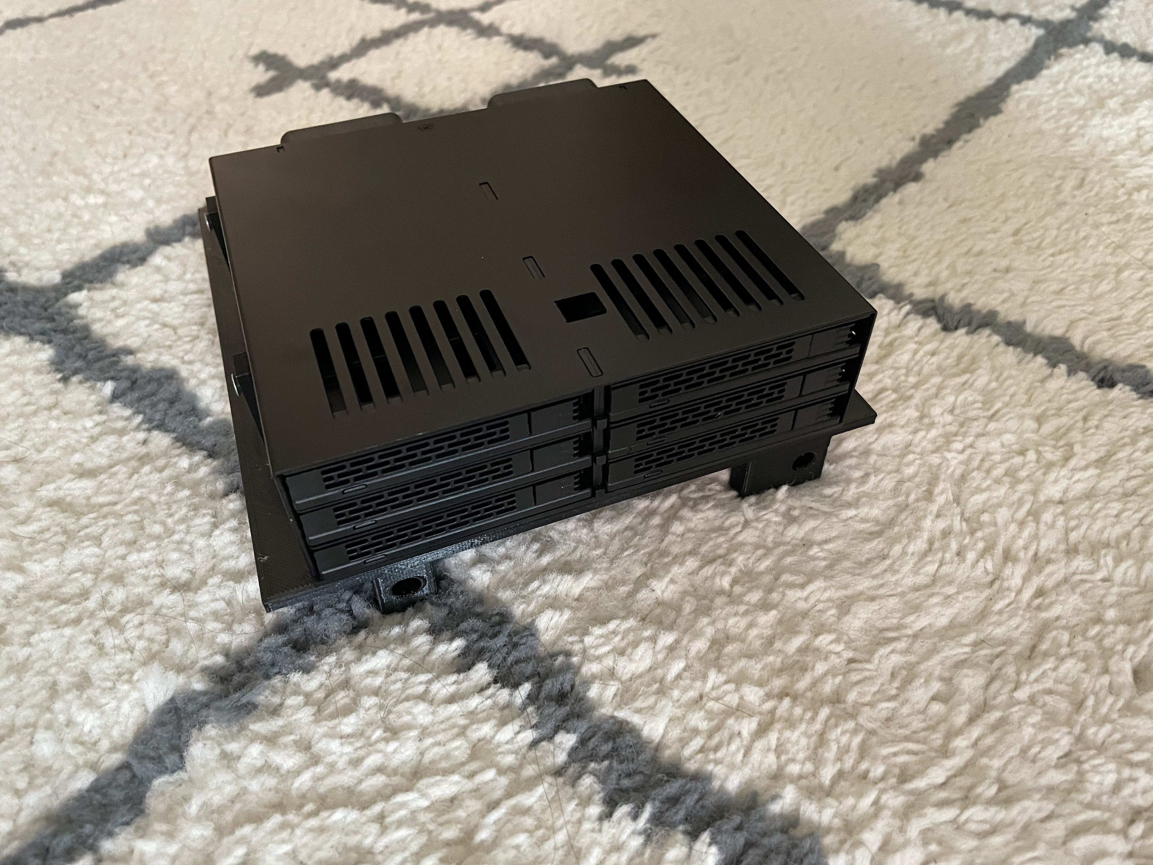
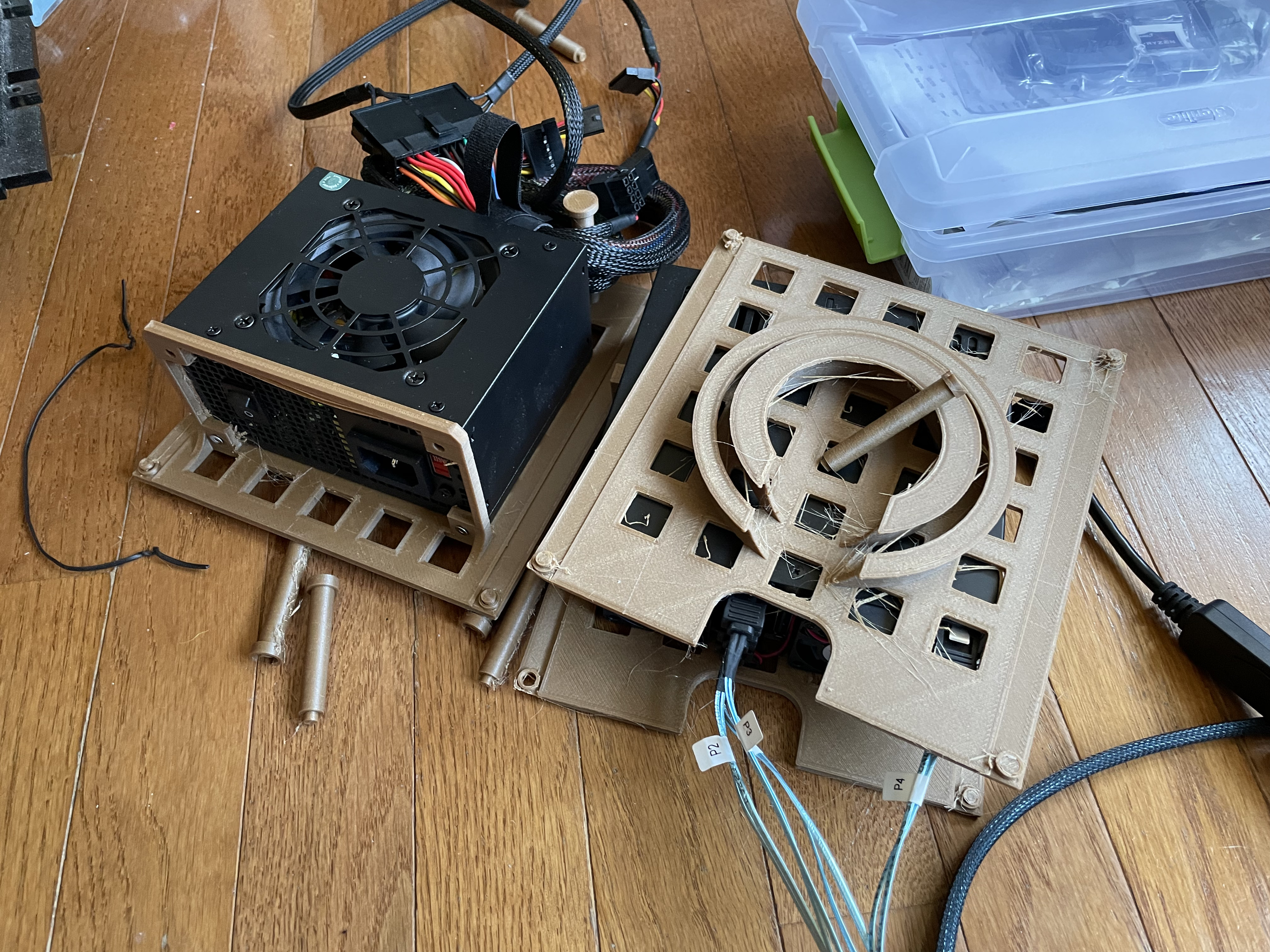
I have mentioned selecting the audio board, selecting the screen, selecting the buttons. One important thing I haven’t mentioned for an audio system is selecting the speakers. The documentation for this board mentions that it can drive 3W, 4Ohm speakers. I tried 3 different ones in different sizes thinking how different could 3W speakers’ sound. Apparently very different. The small ones had a very hollow sound. I went with the bigger speakers. The audio board needed JST-XH 2.54mm connectors in male, which I couldn’t find documented anywhere.
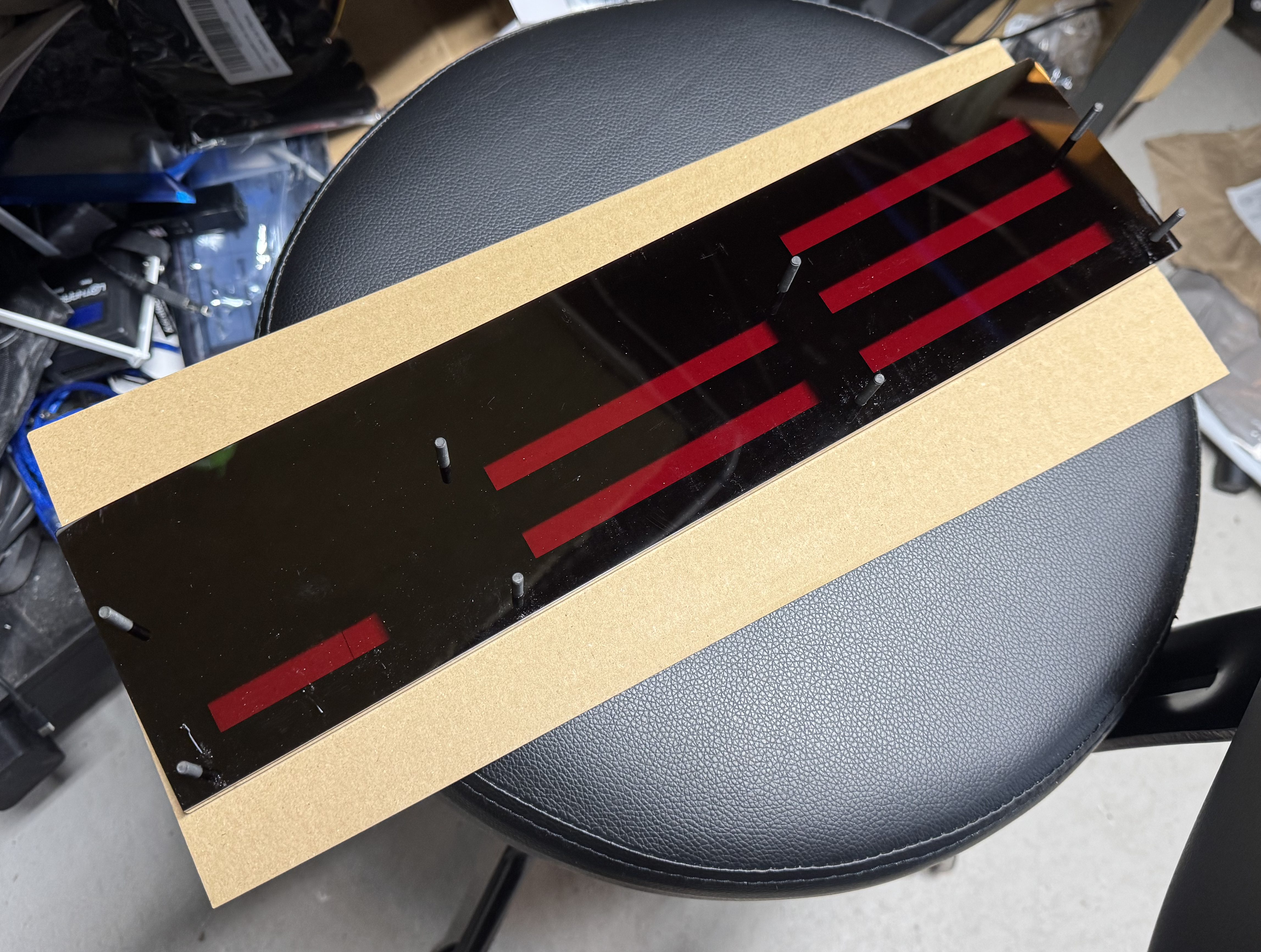
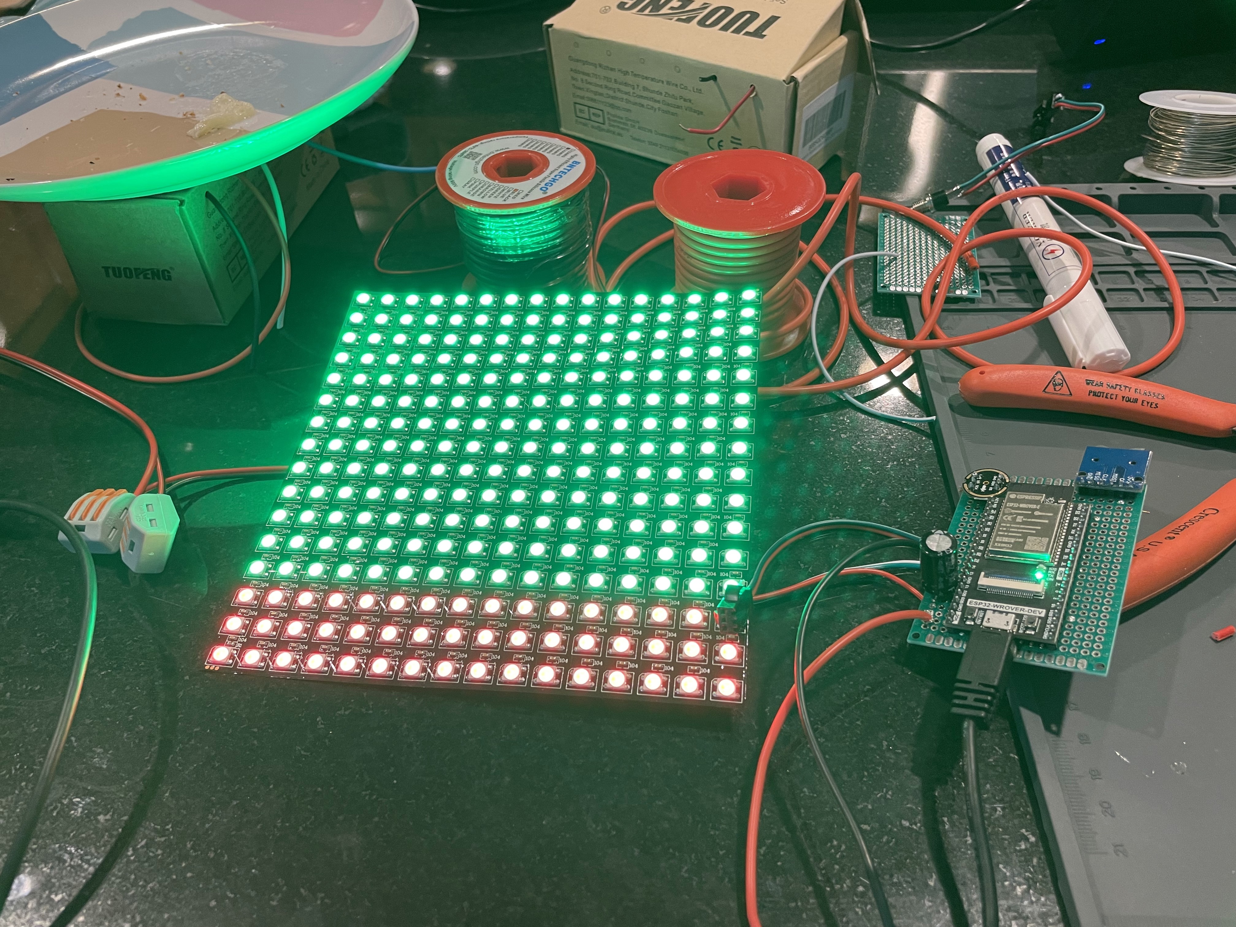
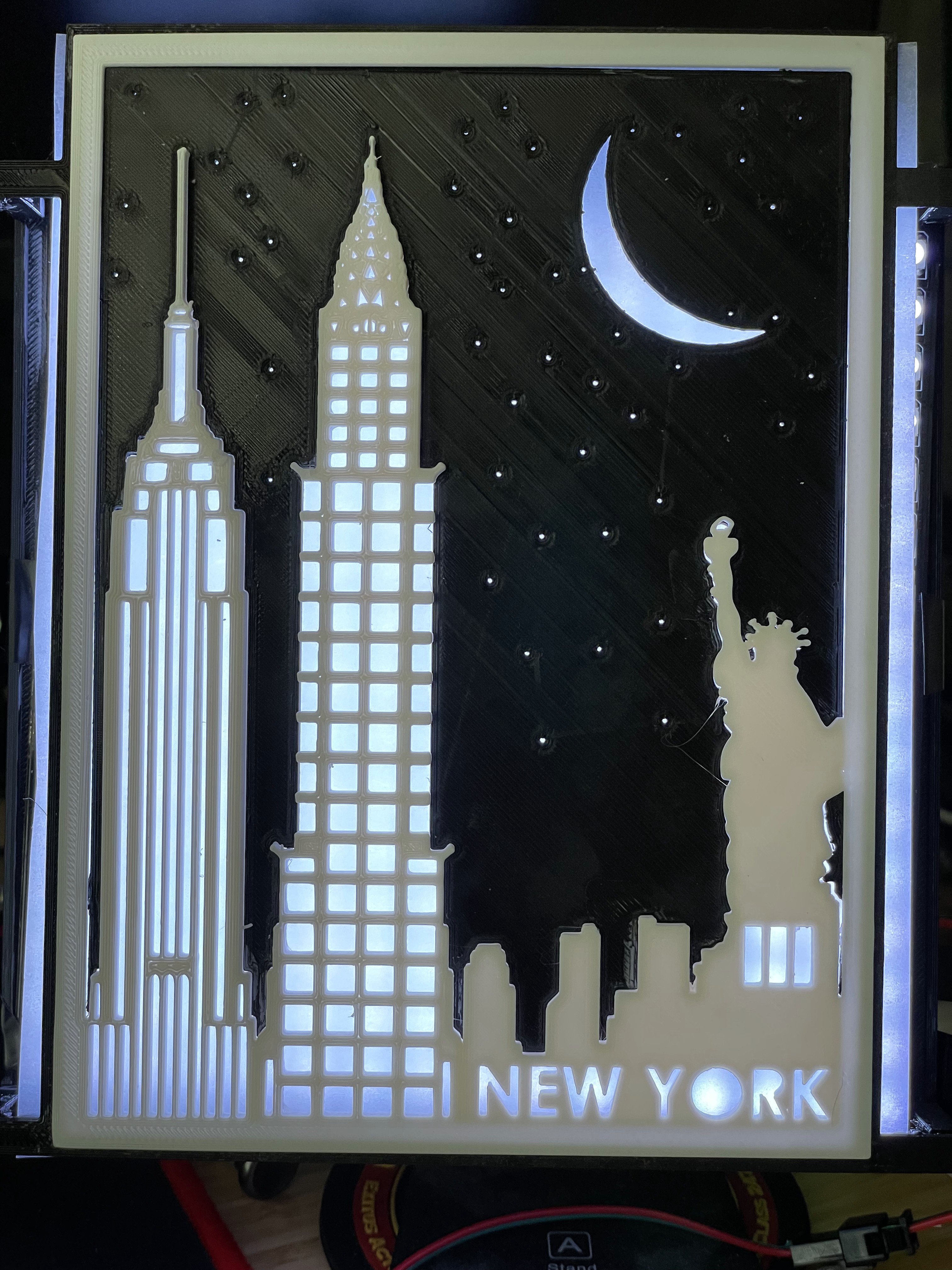
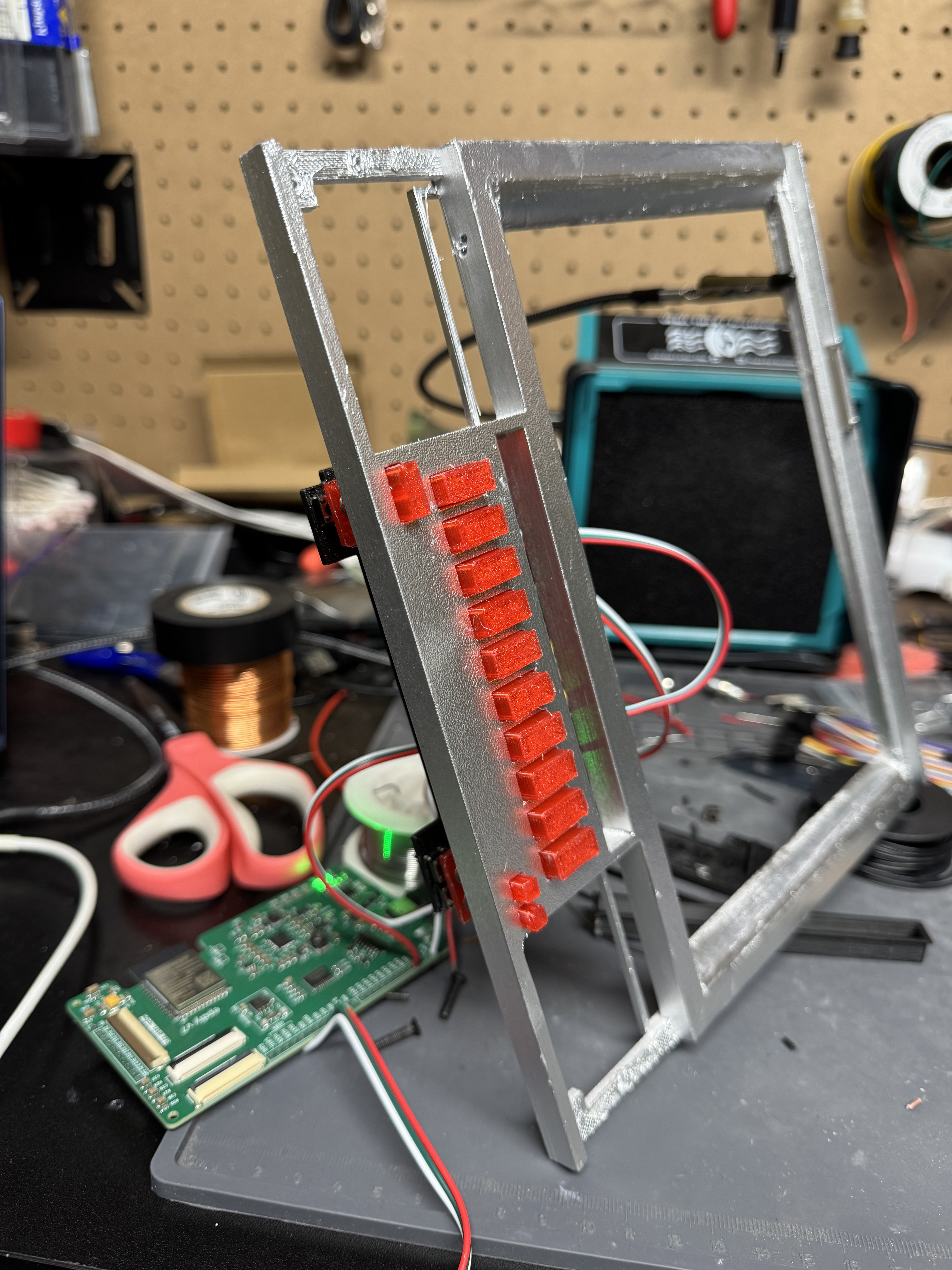
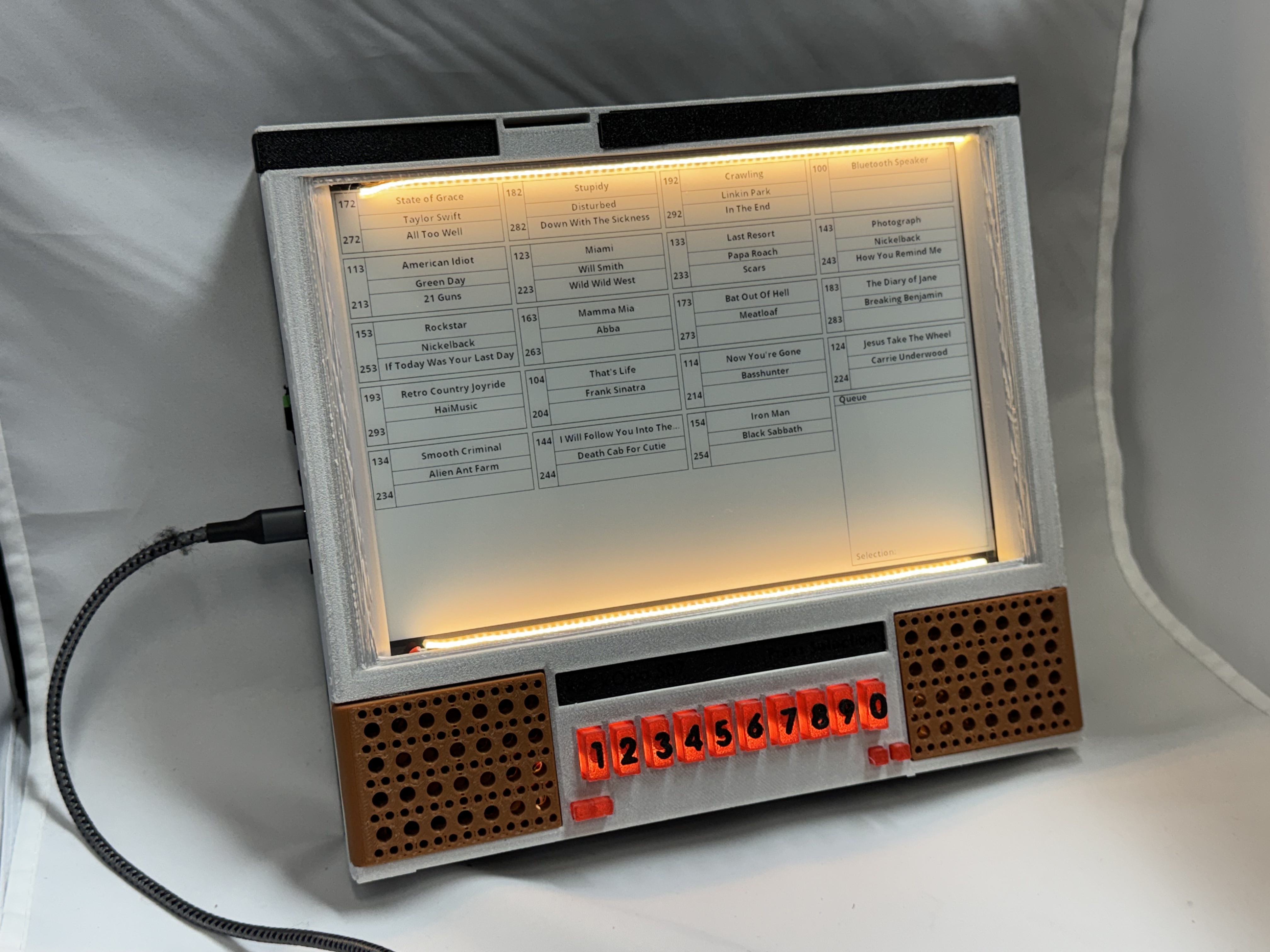
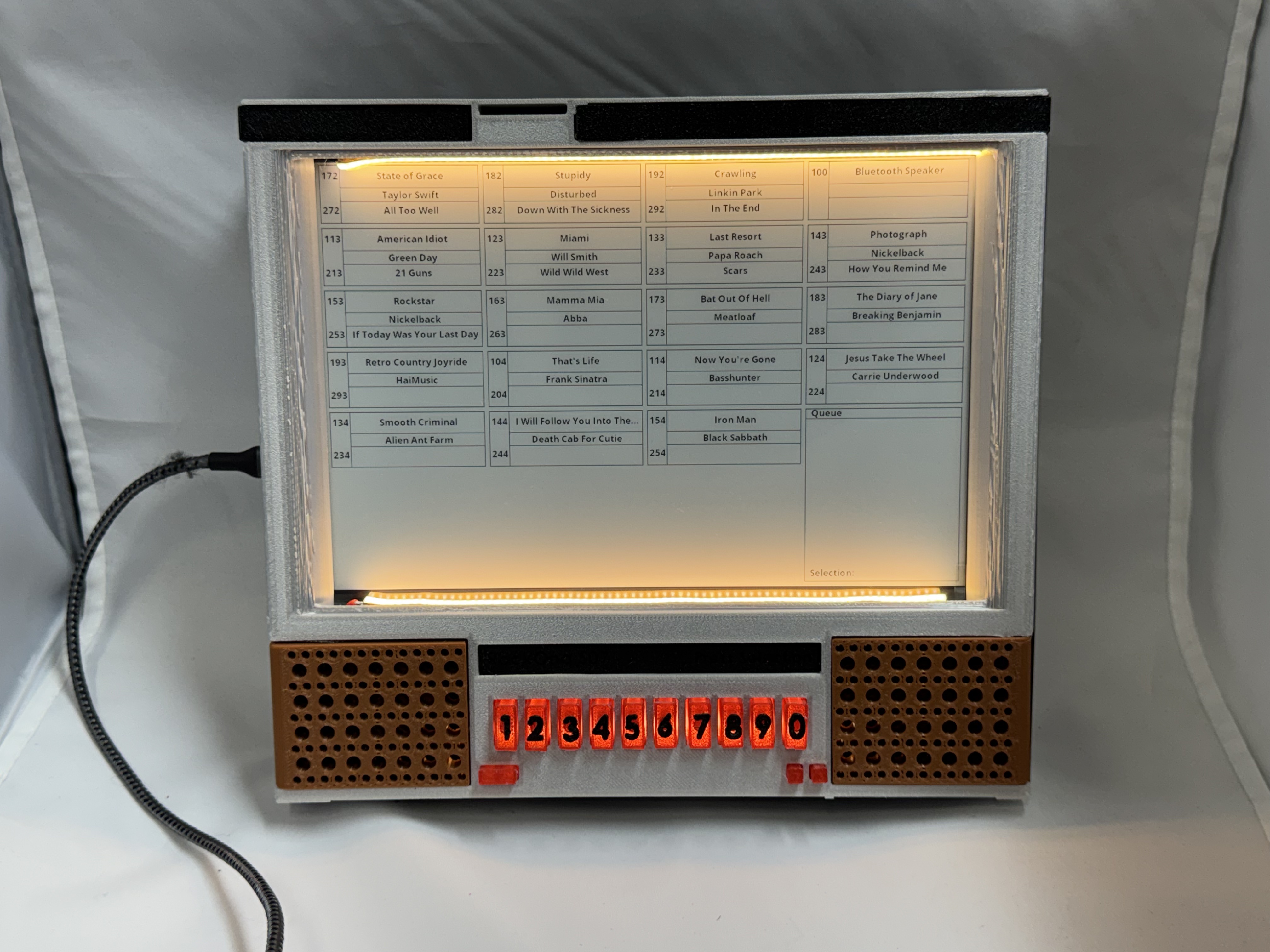
For filament, I did most of the prototypes parts in black. I knew I wanted a silver front from the start, and that led me to trying silver spray paint, more on that in a second. The second big personality piece is the glowing red front buttons. I got transparent PLA filament and put a strip of lights behind the buttons. This worked well. I may have instead put just a few LEDs behind the buttons instead though, because right now the LED strip is tied into the same power source as the front LEDs, and I want to increase the brightness to the buttons but not the front lights. Something to fix in future versions, or a small upgrade. Splitting the button lighting control would also allow interesting effects for if the system is left on for a while with nothing playing, dimming the screen and buttons separately.
Assembly
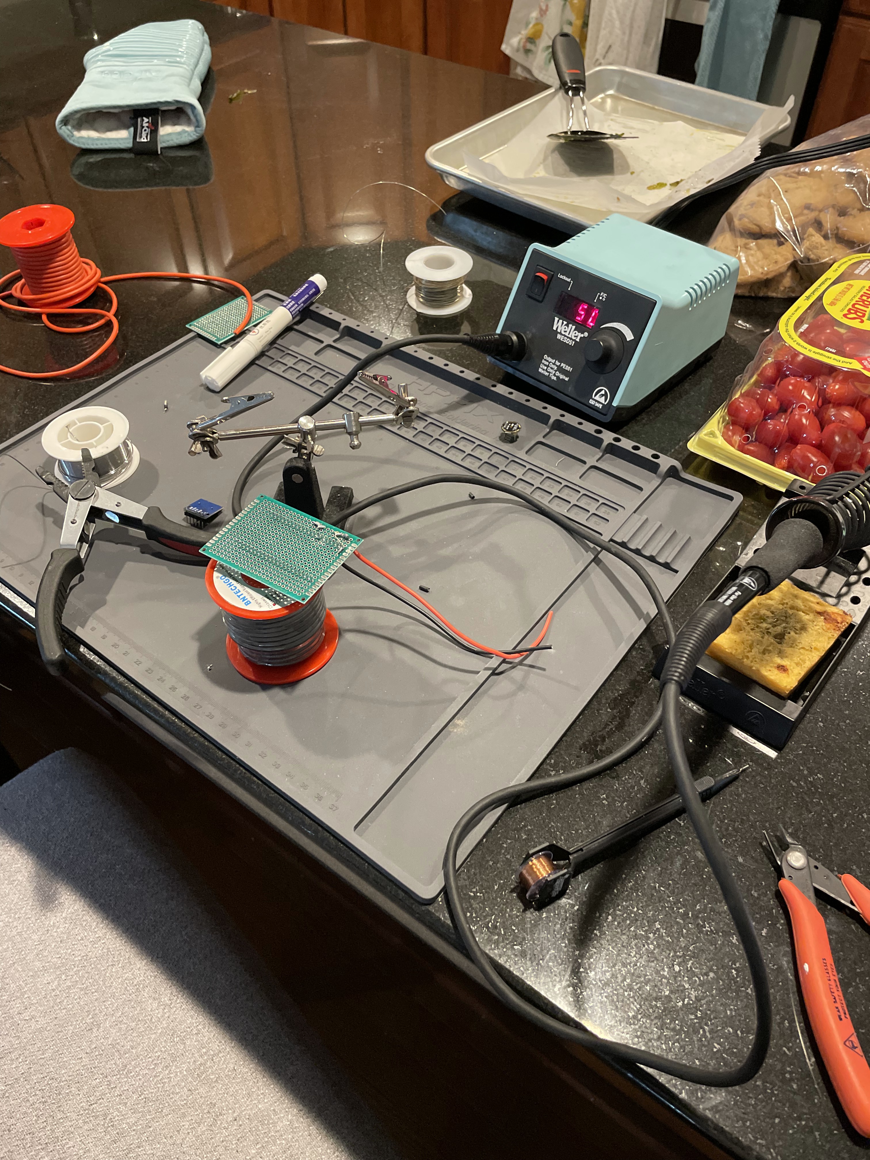
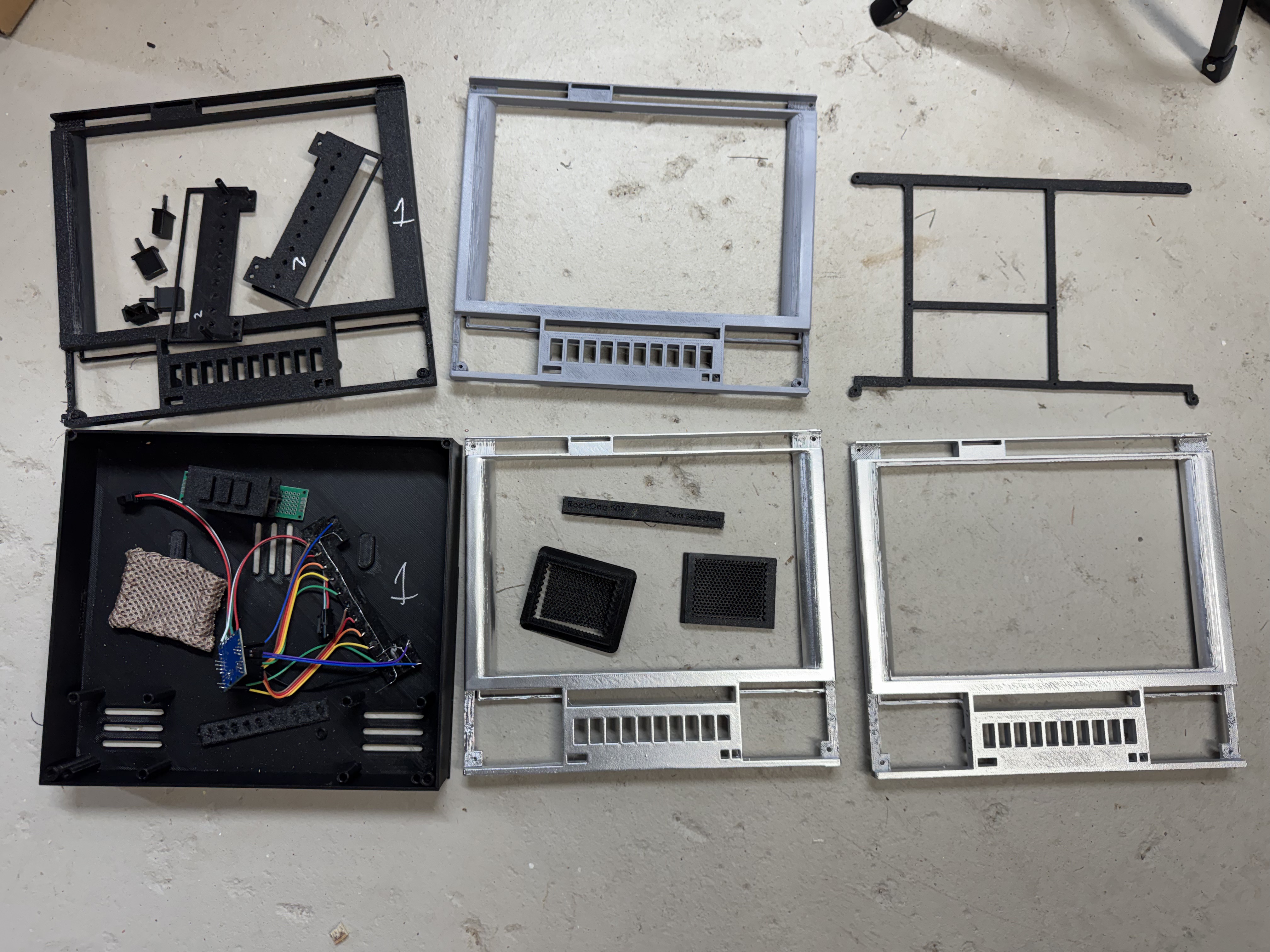
With boards in hand, Claude helping to put the code for them together, and the simple buttons, the hardest part of this whole project was printing it out and putting the pieces together. I will readily admit I am not the best spray painter. It also didn’t help that the chrome-looking spray paint wants 65F-90F degrees and 60%+ humidity to properly paint. Being winter around NY left me limited days where I could attempt different spray-painting techniques. I tried the whole proper 3D printing, sanding, filling, sanding, priming, sanding, spray painting for the first unit. It came out, meh. I think I over sprayed. I ended up making two units, one where I tried a few front plates, with different sanding and spray-painting techniques, then one that I just got silver filament and 3D printed it, calling it a day.
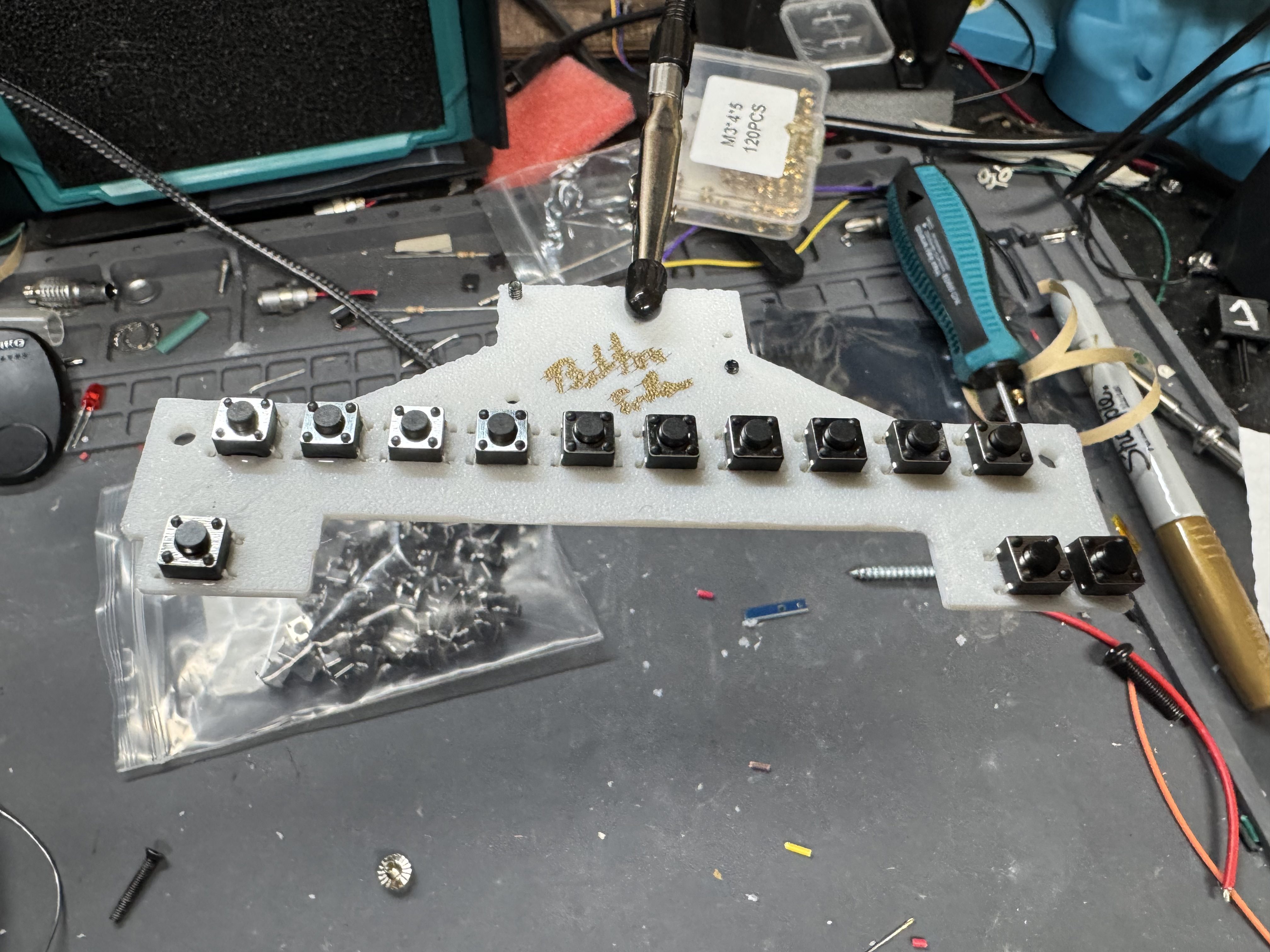
Button Assembly
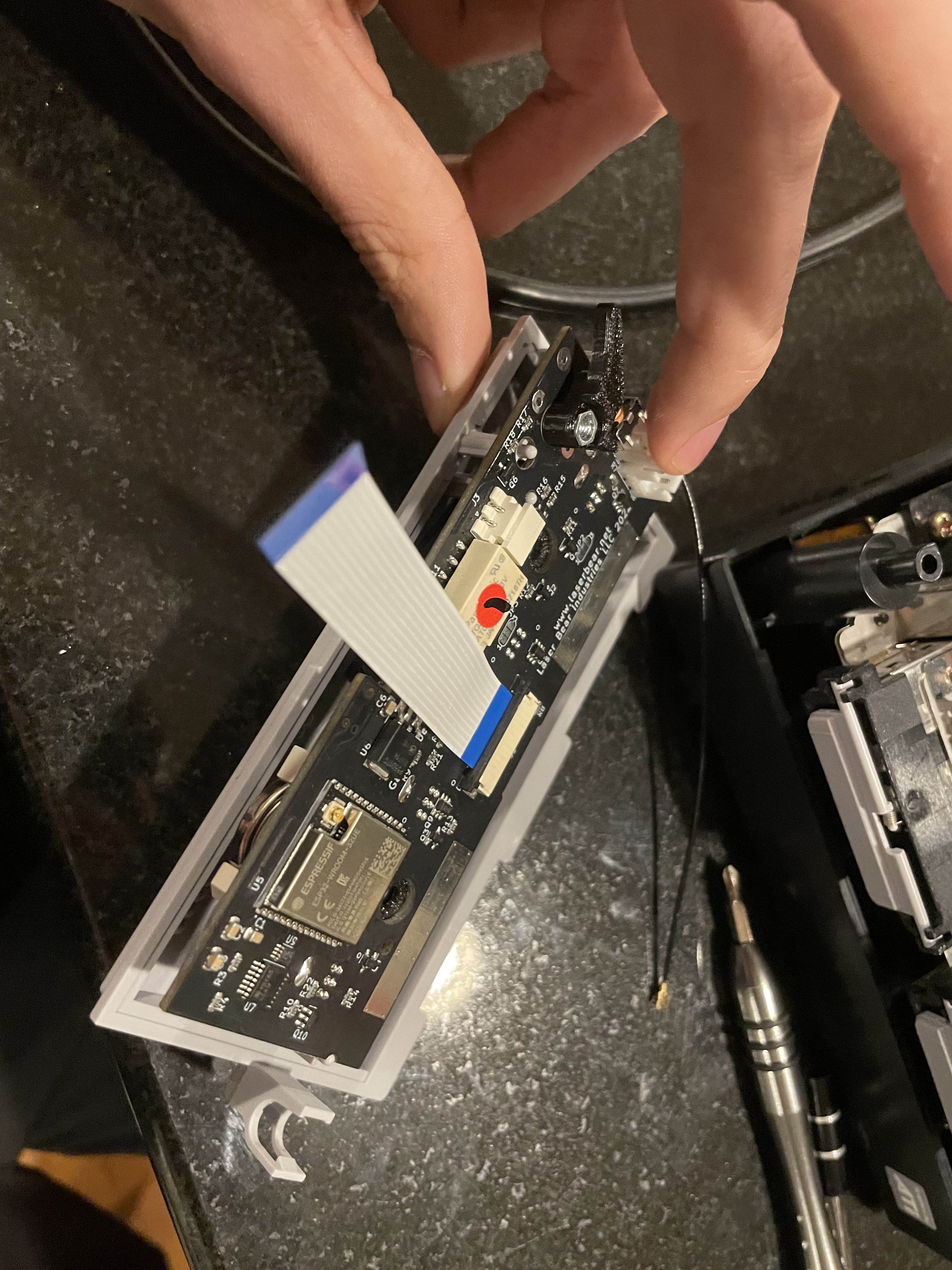
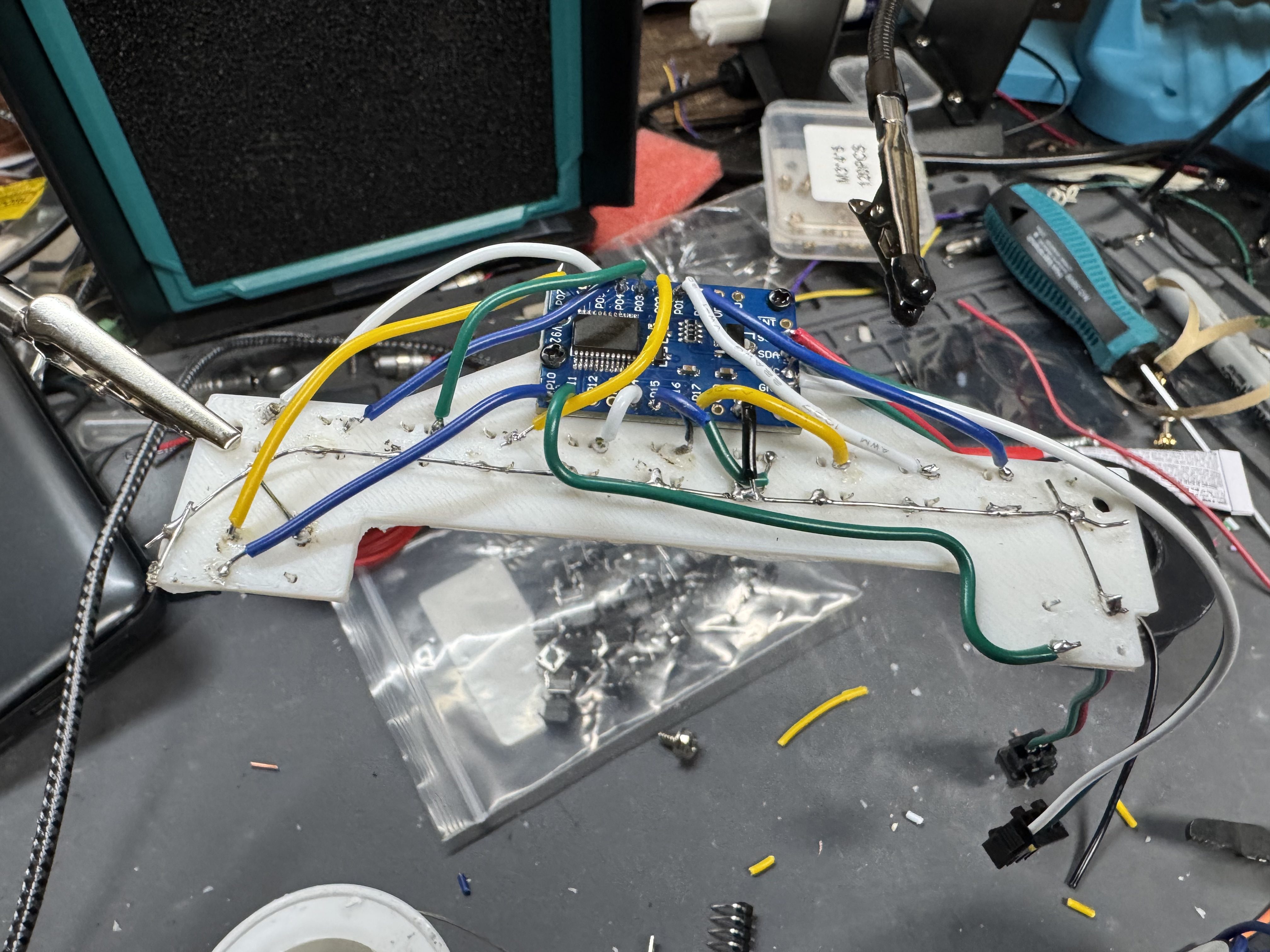
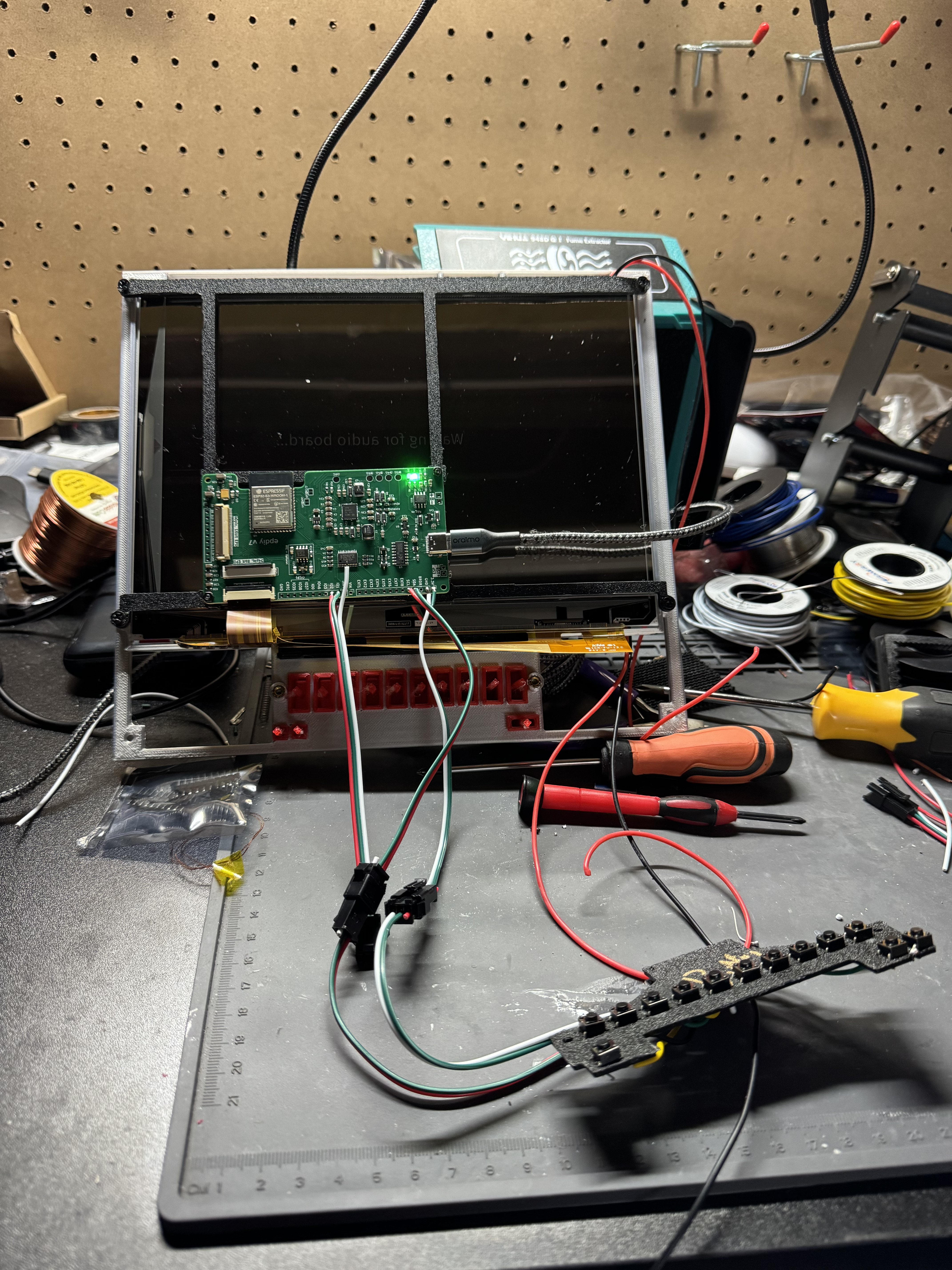
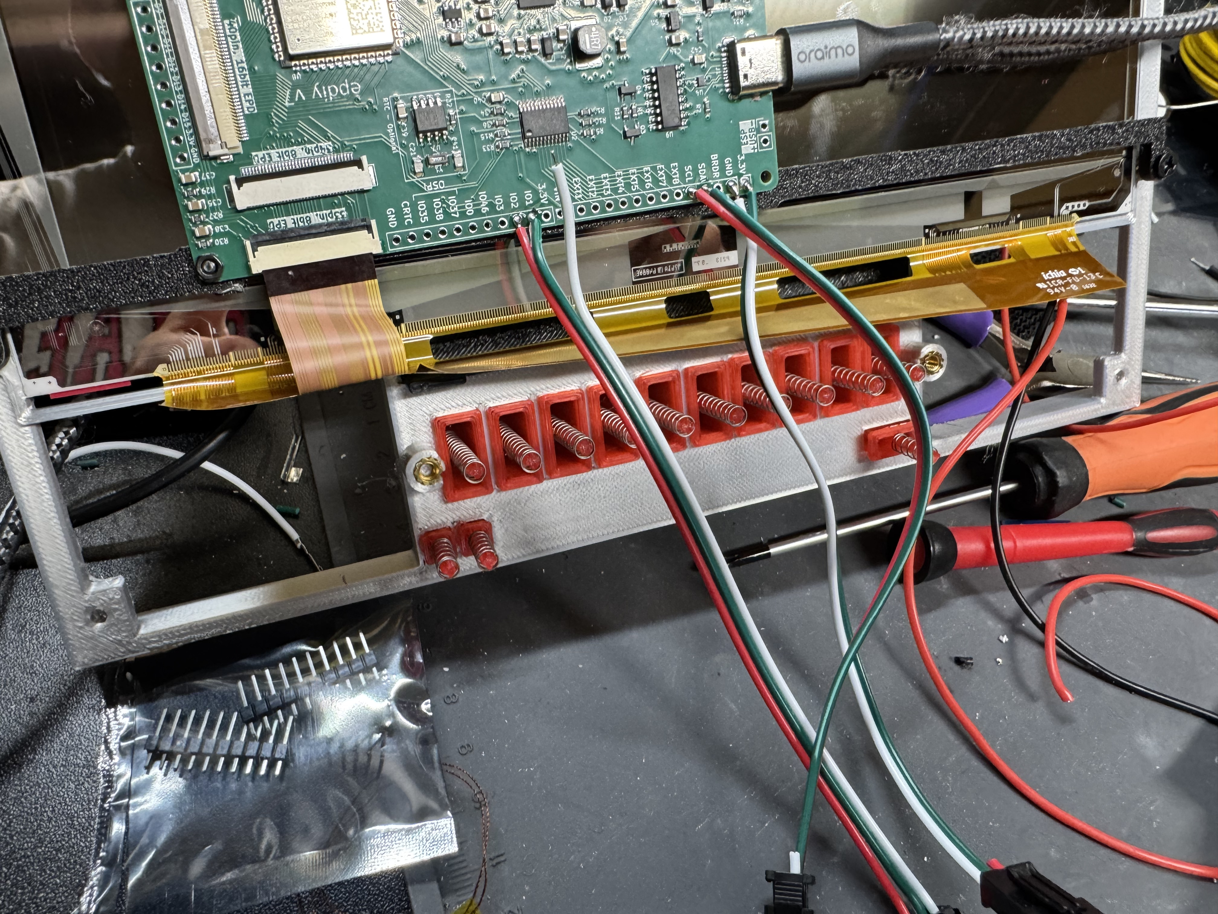
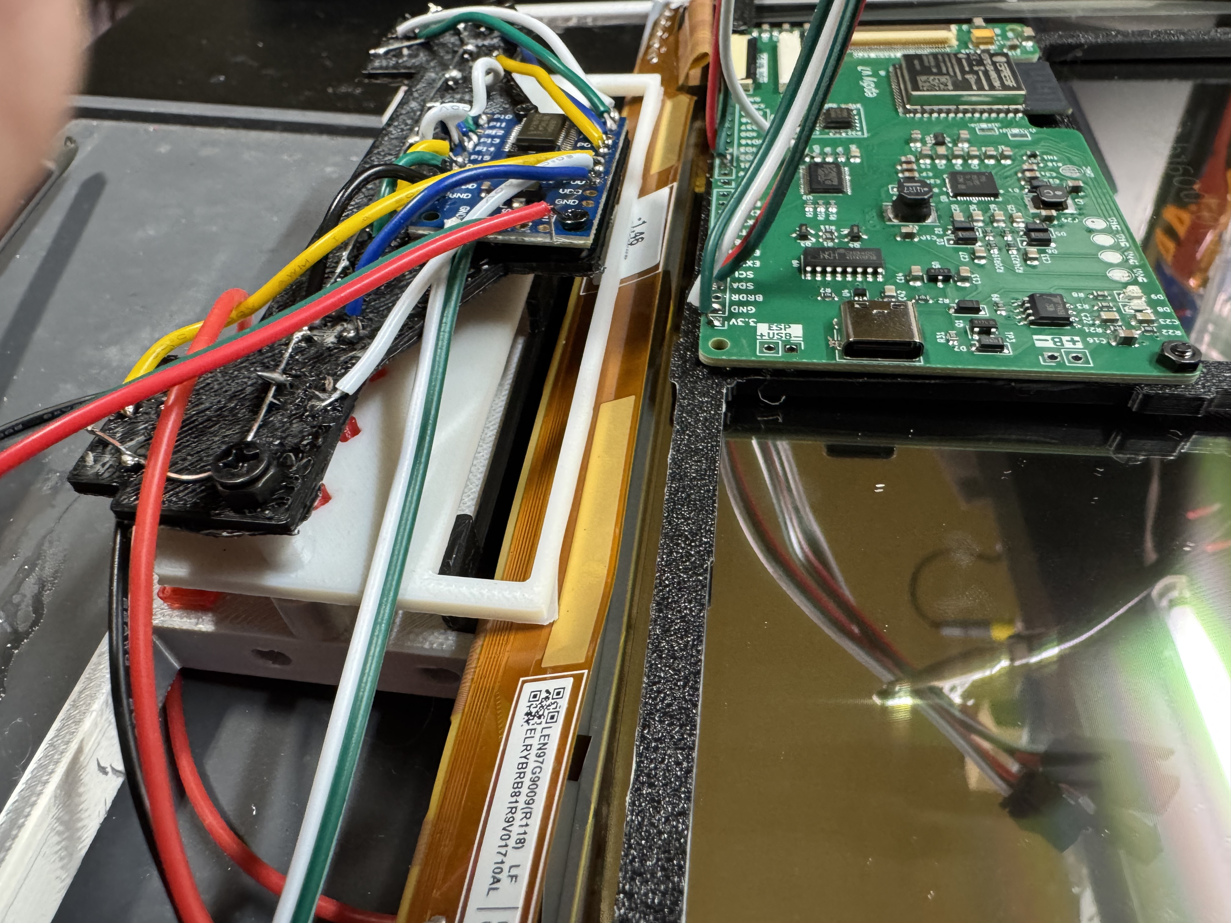
I assembled the front. Soldering the buttons to a PCF8575 IO Expander, this helped give me more buttons over I2C to the EPDiy board. I created a version 1.1 of the button board. The first version had wires going everywhere which made it hard to put into the case. The updated version I put the chip on the same 3D printed part, greatly shortening the runs and making it much cleaner inside. I did get one of those PCF8575 that was bad, and that took me a bit to track down, it would spray out random buttons being hit. I thought it was my circuit. One great upside to the PCF8575, it uses 2 wires for power, and 2 for data, making the whole button assembly very self-contained.
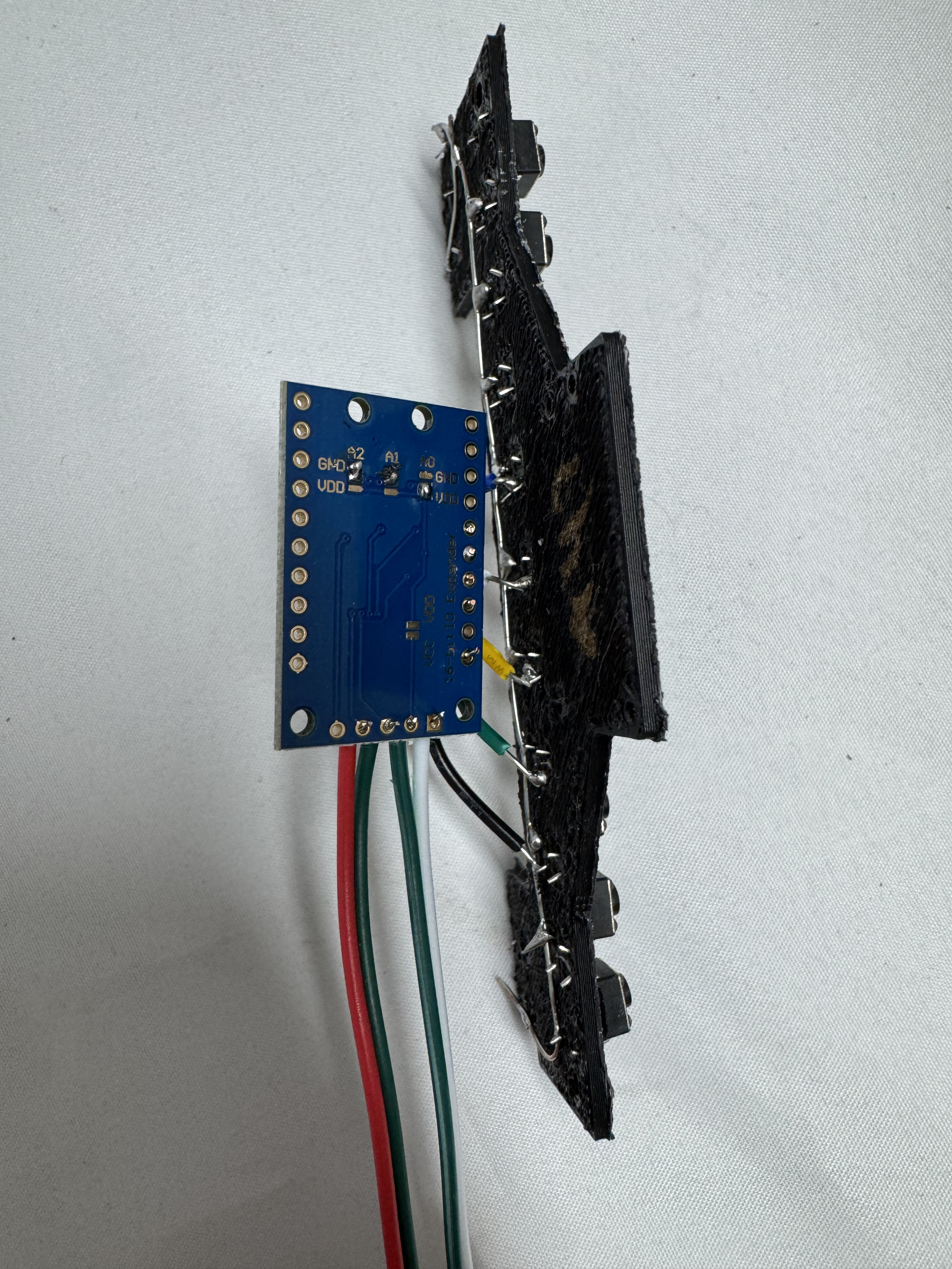
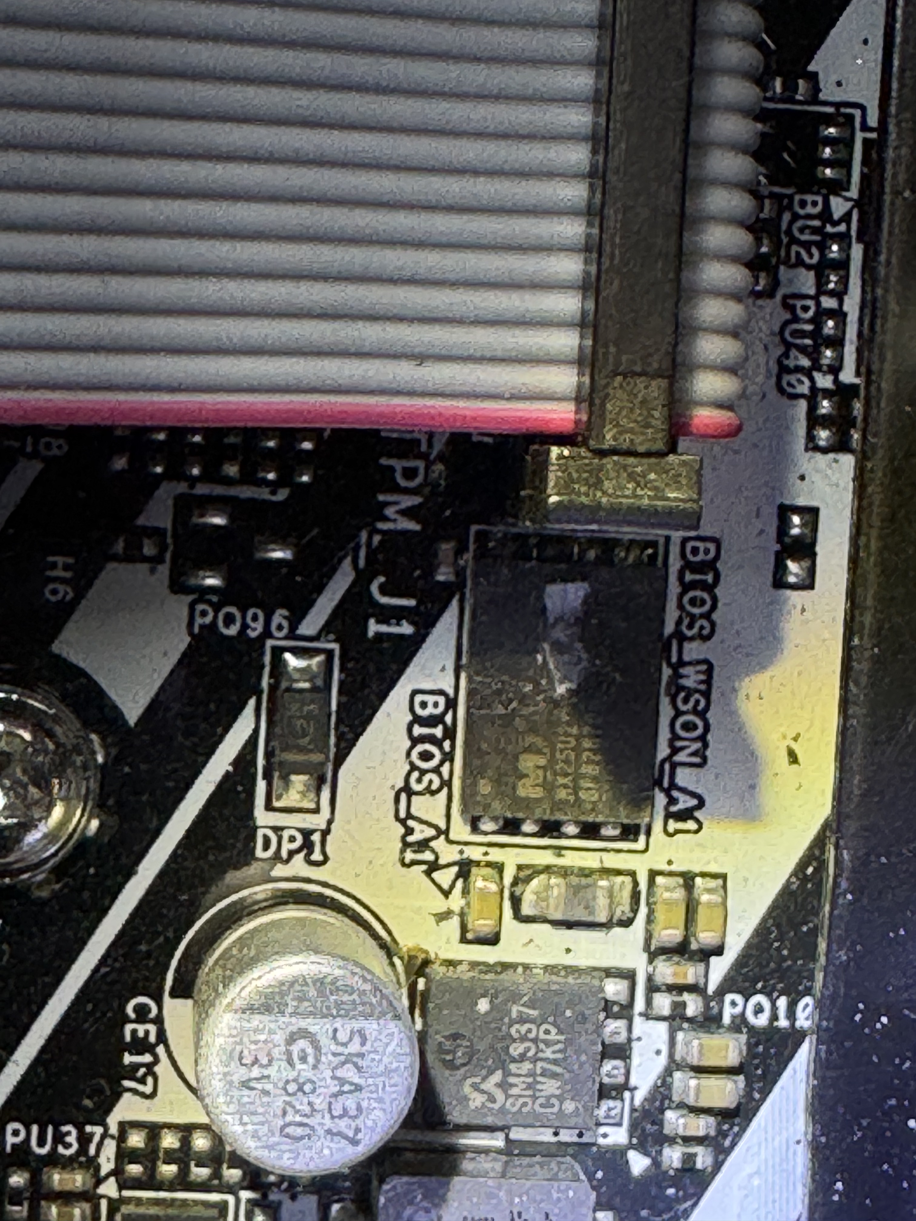
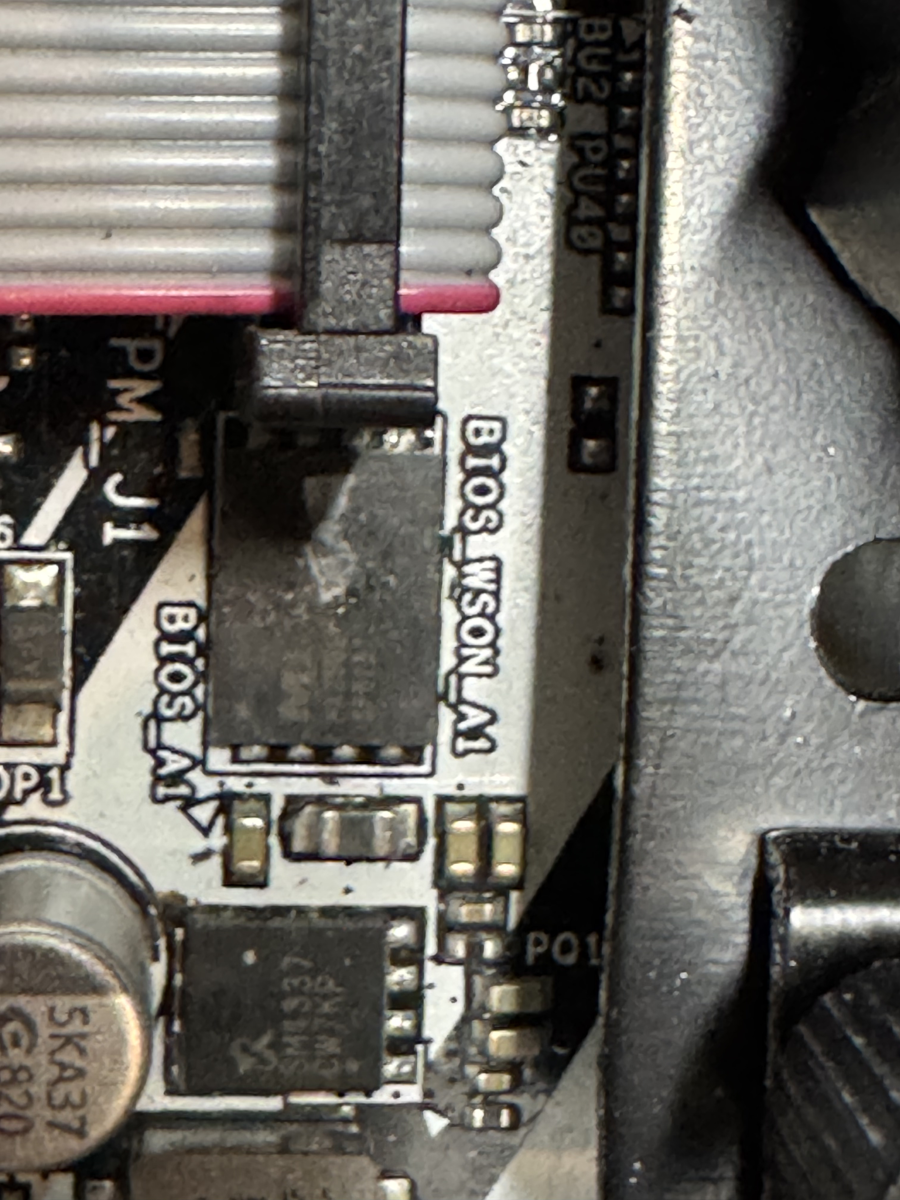
An important note about EPDiy and PCF8575. The E-Ink part of the panel uses 0x20 ID on I2C to communicate. I had to solder on the back of the PCF8575 to change its ID to 0x21.
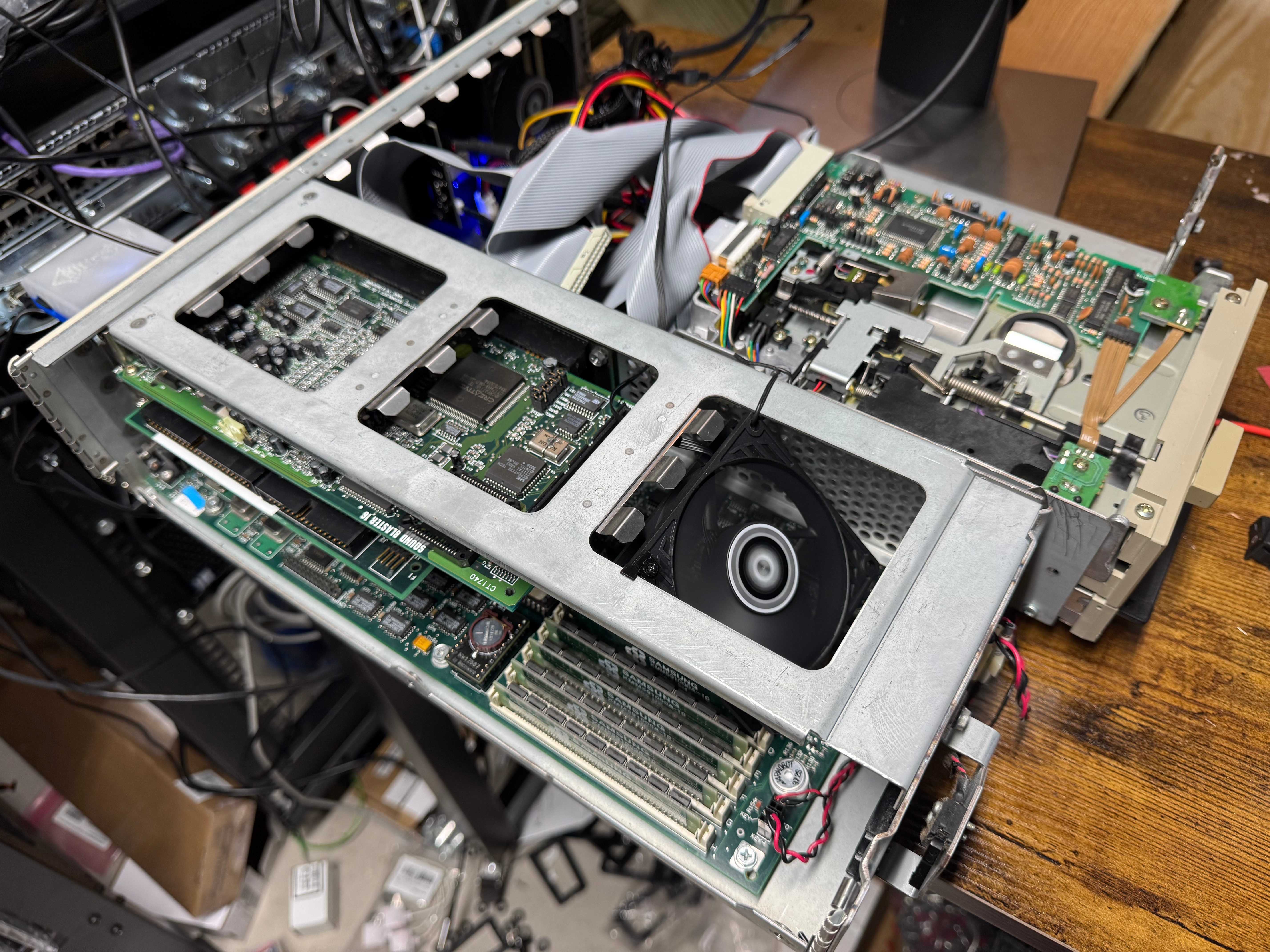
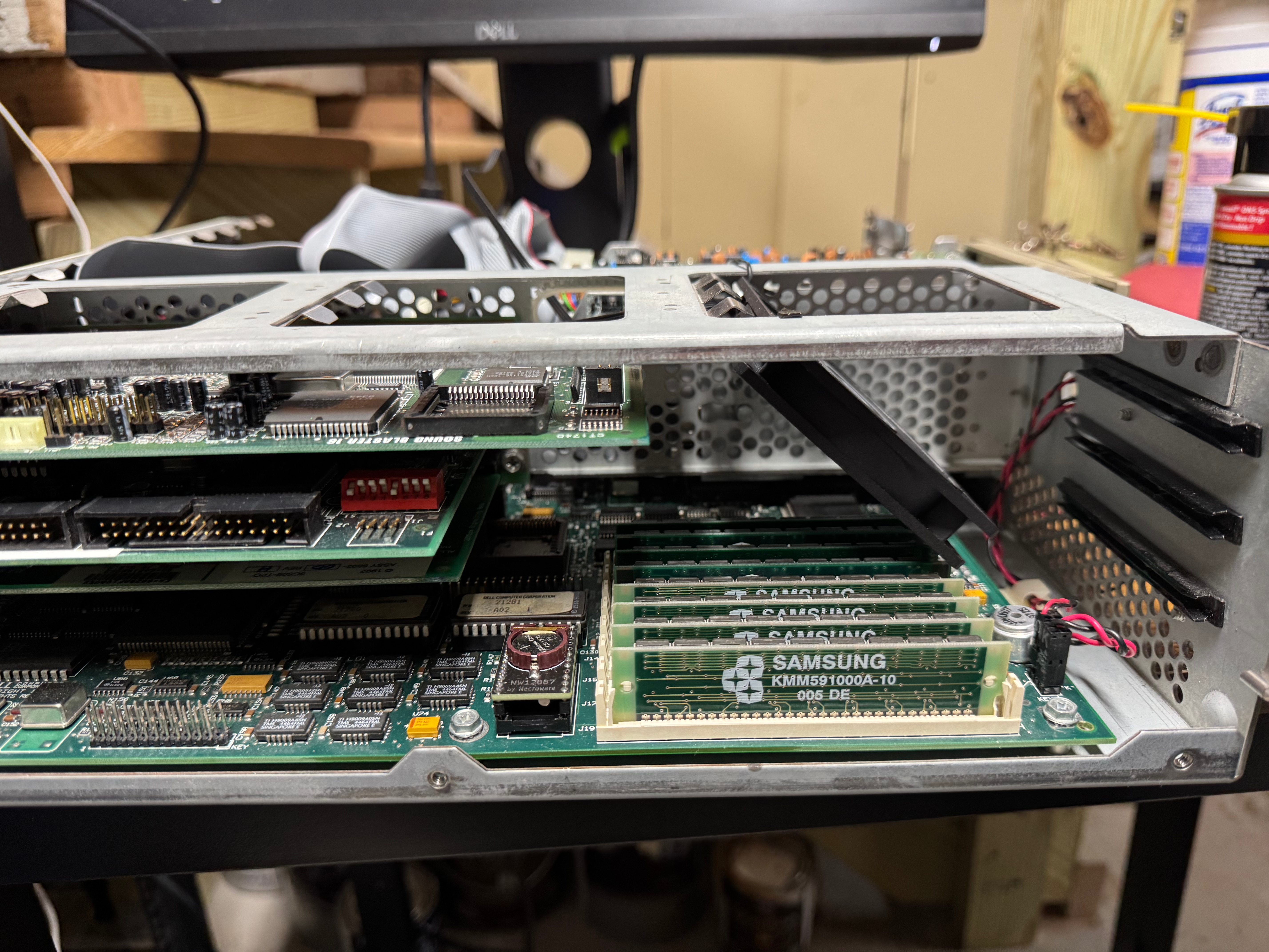
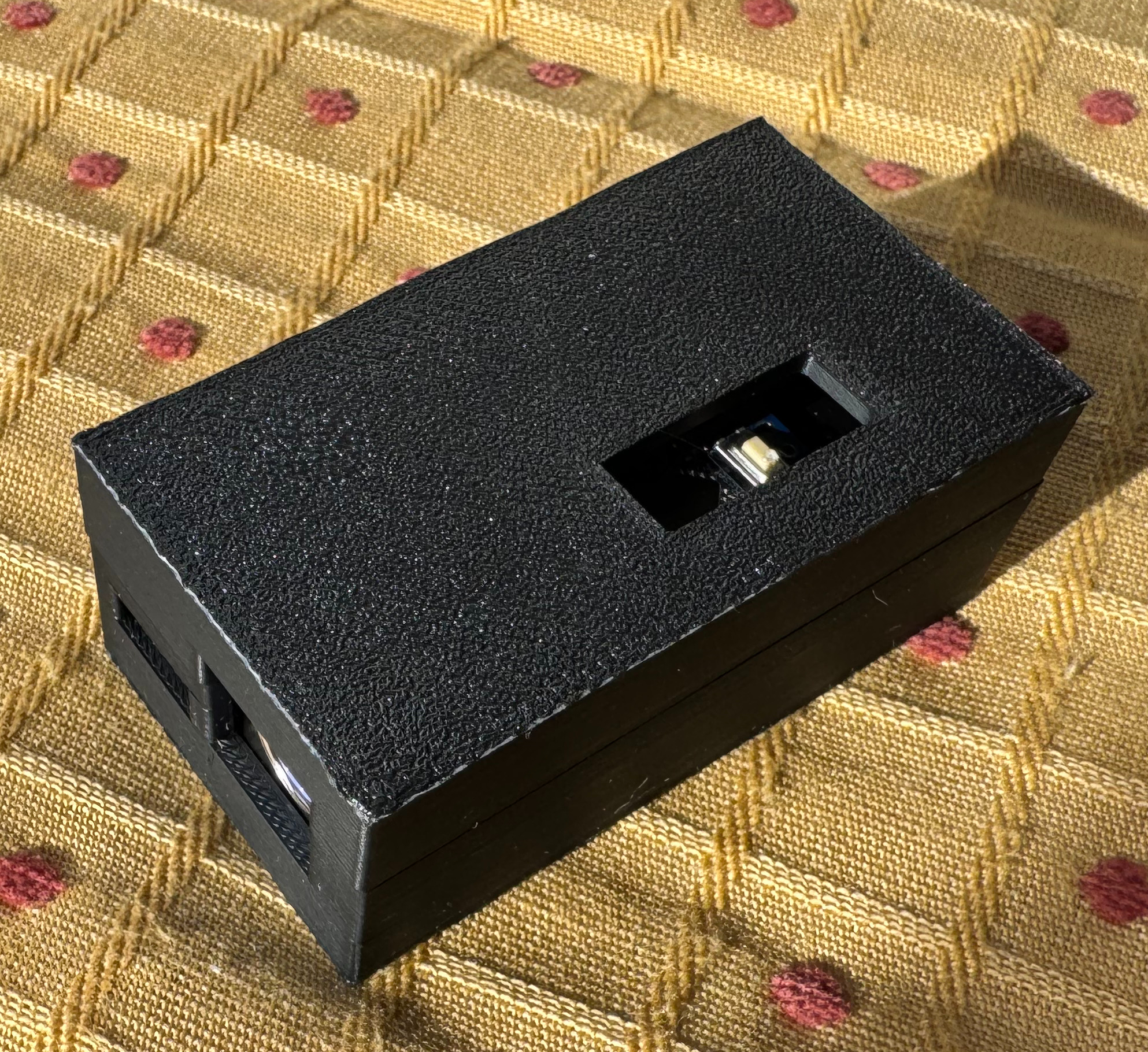
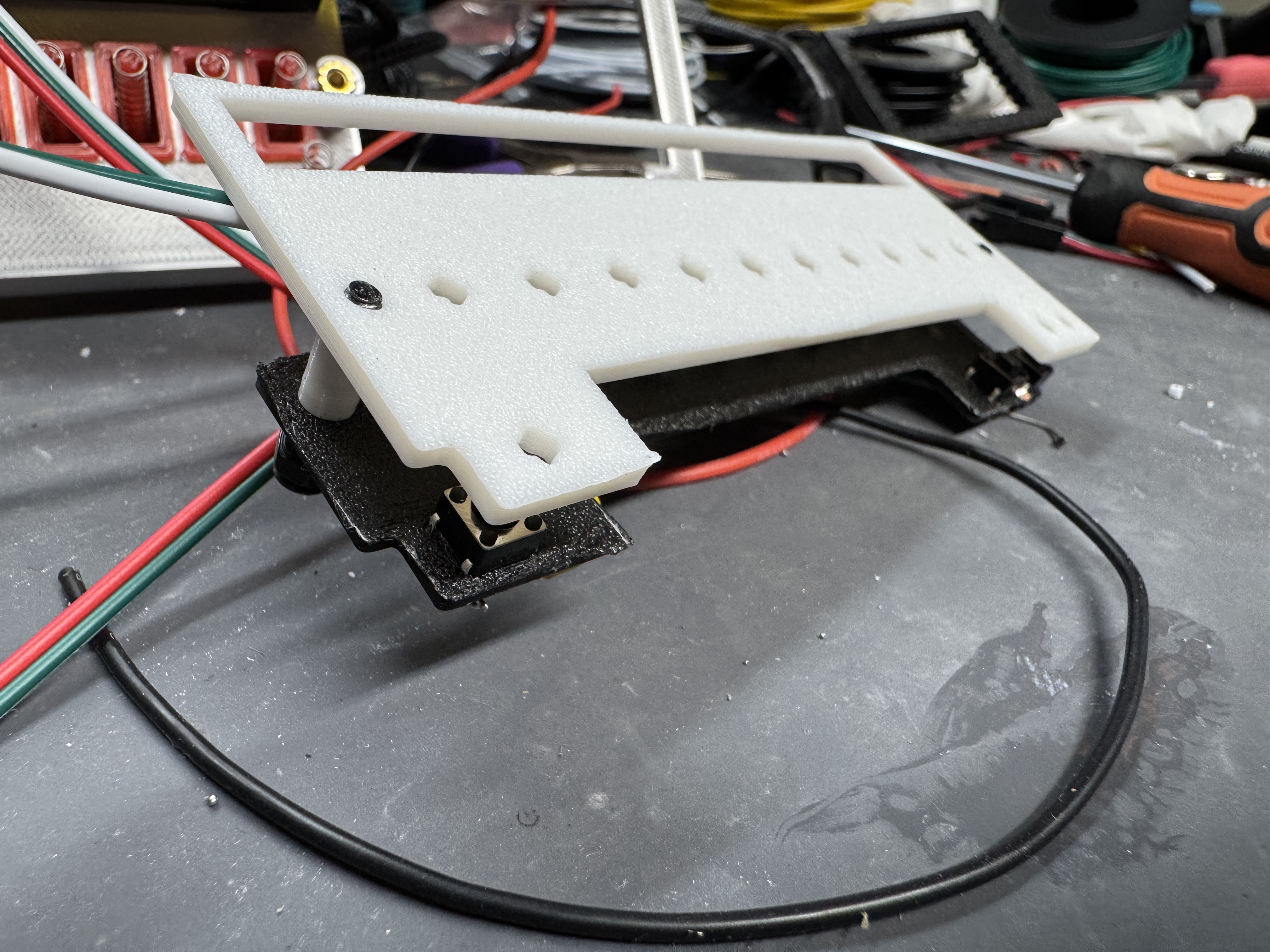
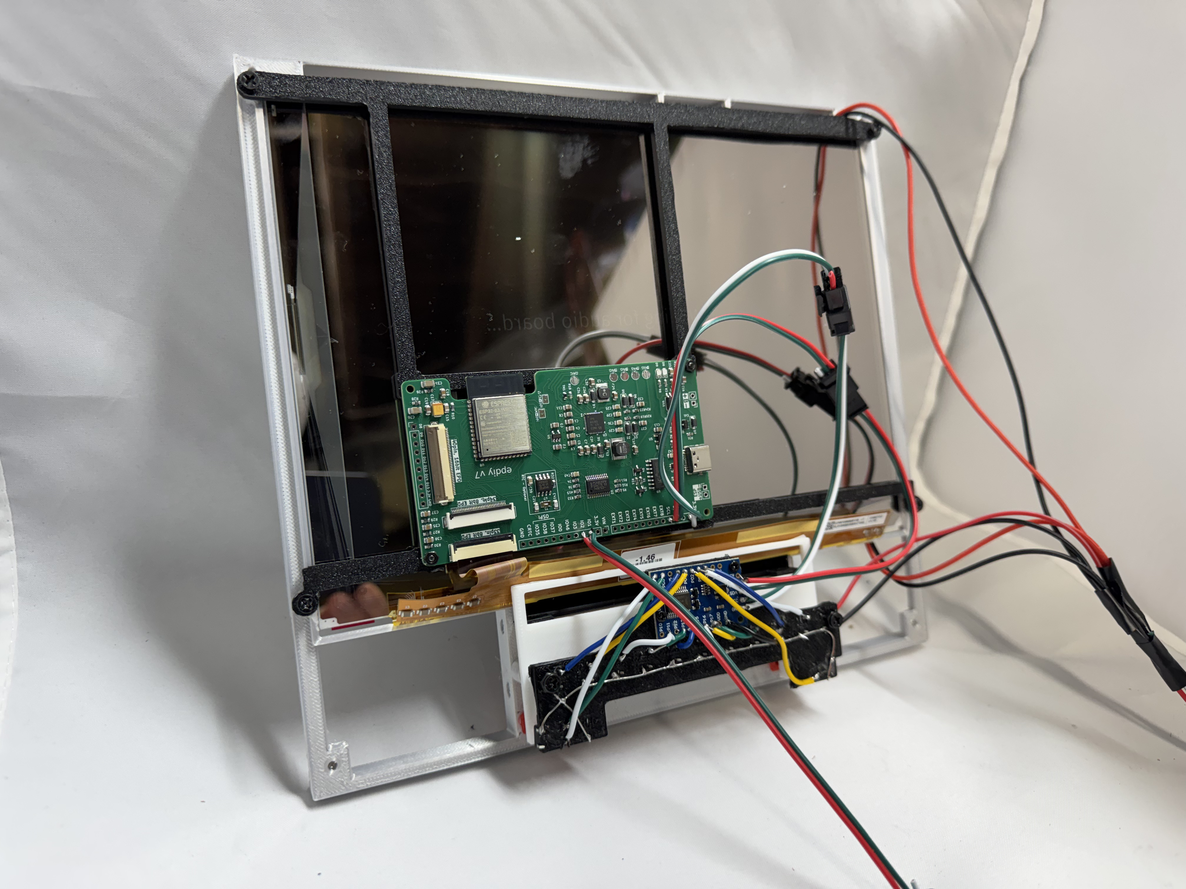
I got the final front panel and installed the full button assembly. I put the EPDIY onto the bracket for the screen. Then installed the E-Ink screen and its backing bracket. I had put LEDs from an LED strip I got on the front below the screen, and above, then another short strip behind the transparent buttons. Soldering the wires onto the “easy to cut” LED strip was not fun. I soldered all the LED strip positive wires together, and then the negative wires; connecting them into one of the quick connect connectors I had. The front panel was done now. I wrote the IO Board code to the ESP32 (which I ended up doing multiple times), and it was good to go. I did originally want to have text with lights behind it in the top cut out area of the front, and above the buttons, but this was added complexity for a small nice visual thing. I may add that in another iteration.
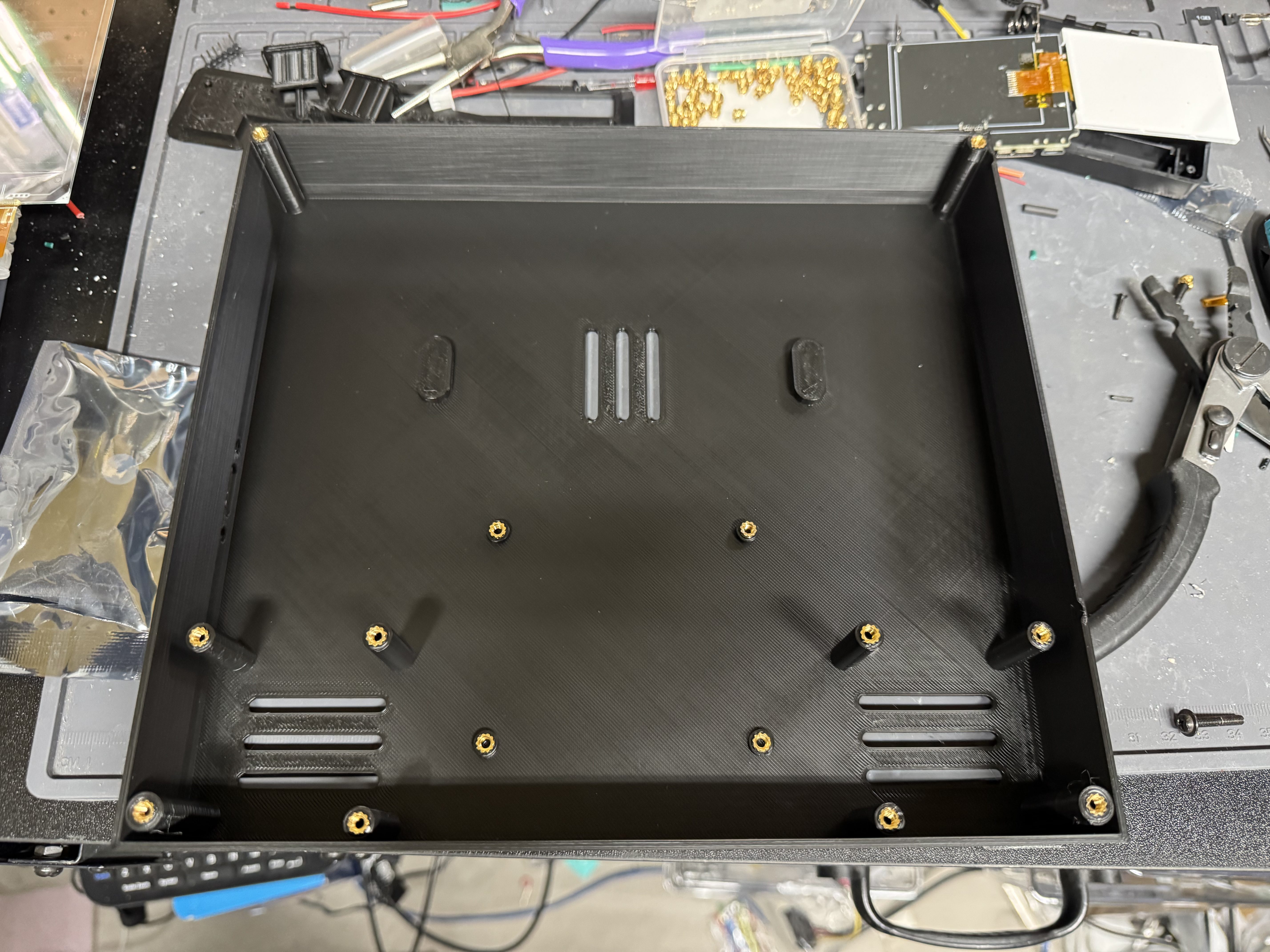
I made wide use of one of my more recent favorite 3D printing tools, heat set inserts. They are tiny metal screw points you melt into your print with a soldering iron. They give great M3, M4, or M5 mount holes that you can use in a project and not worry about wearing out the plastic. They are also $10 for 120 of them.
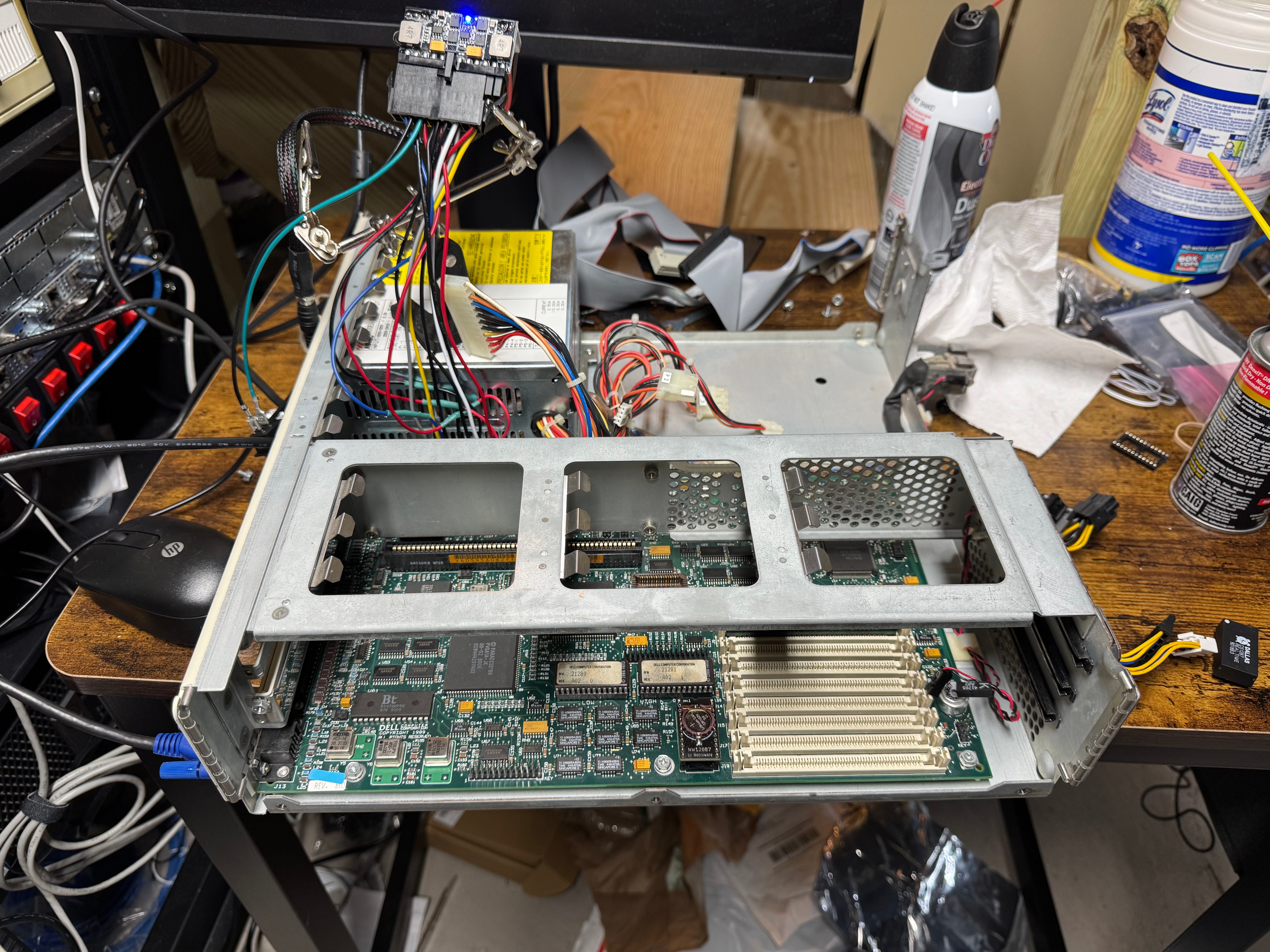
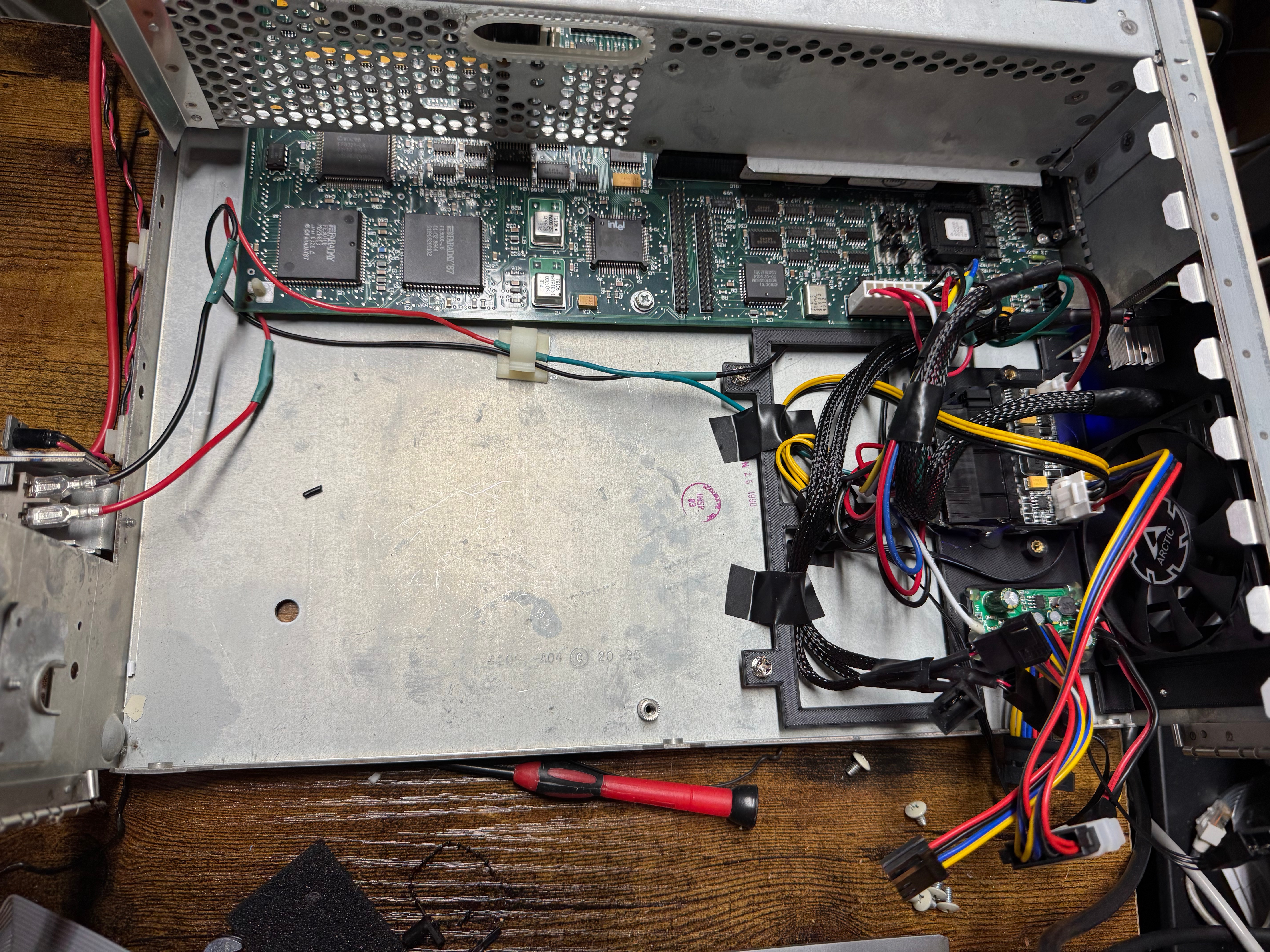
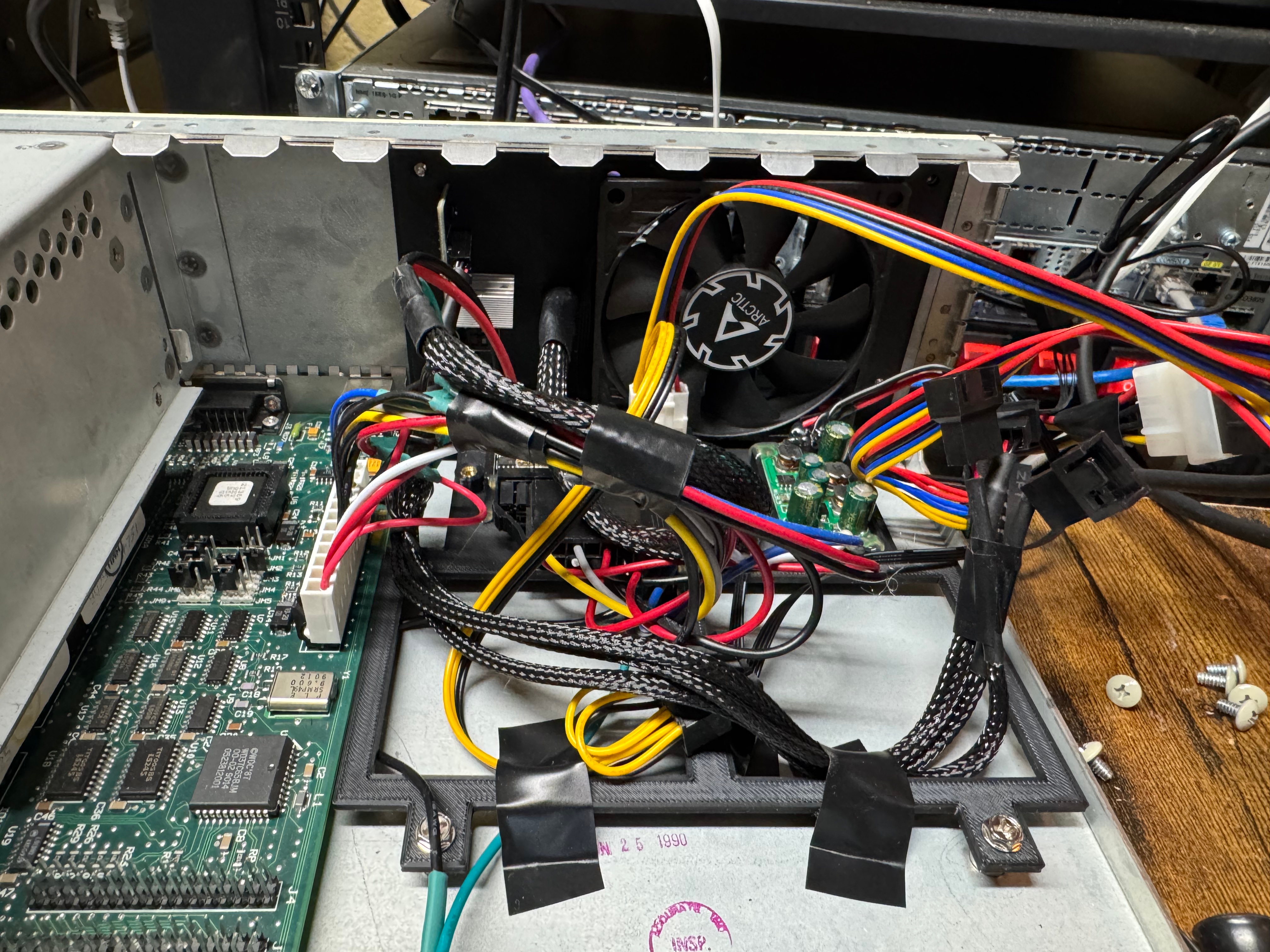
Electronics
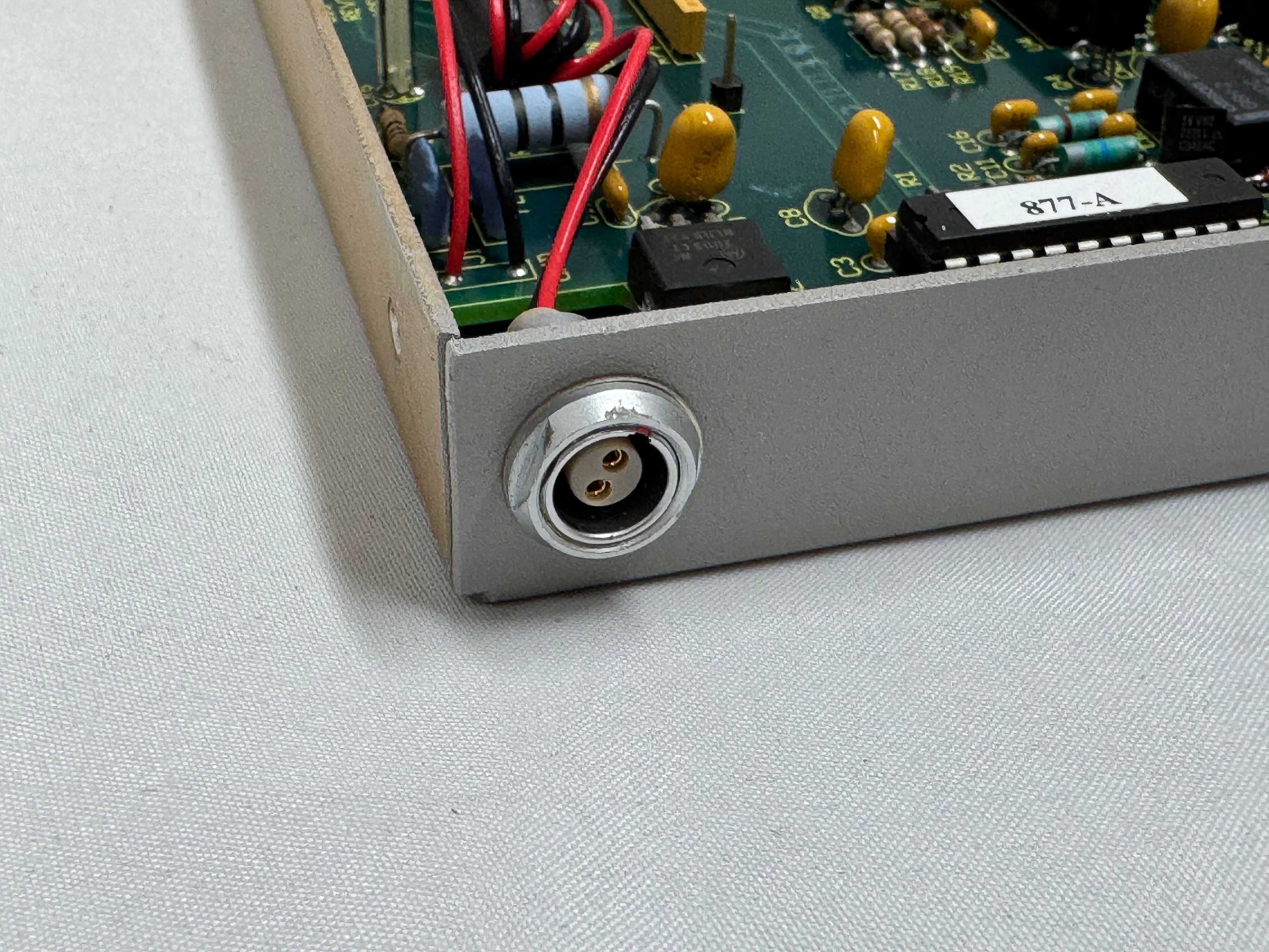
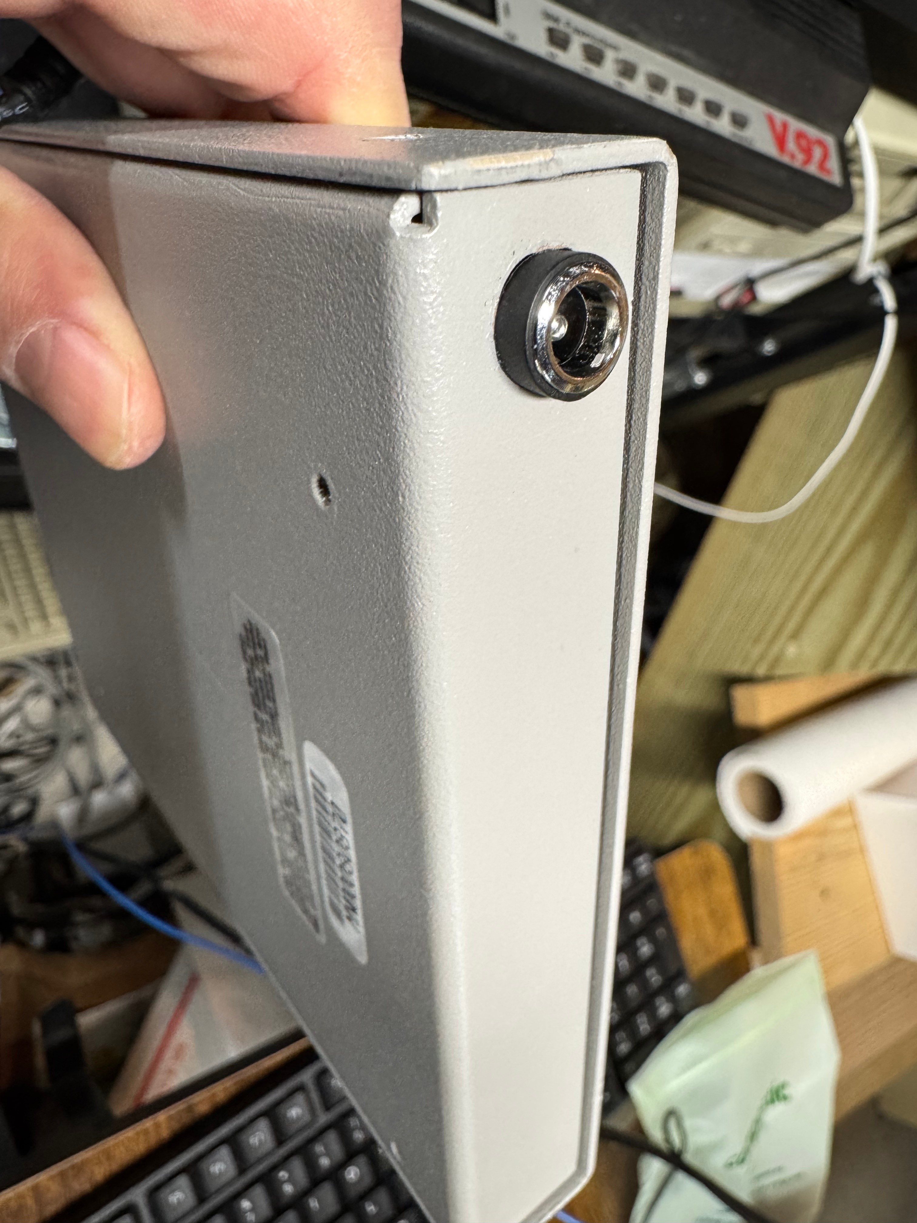
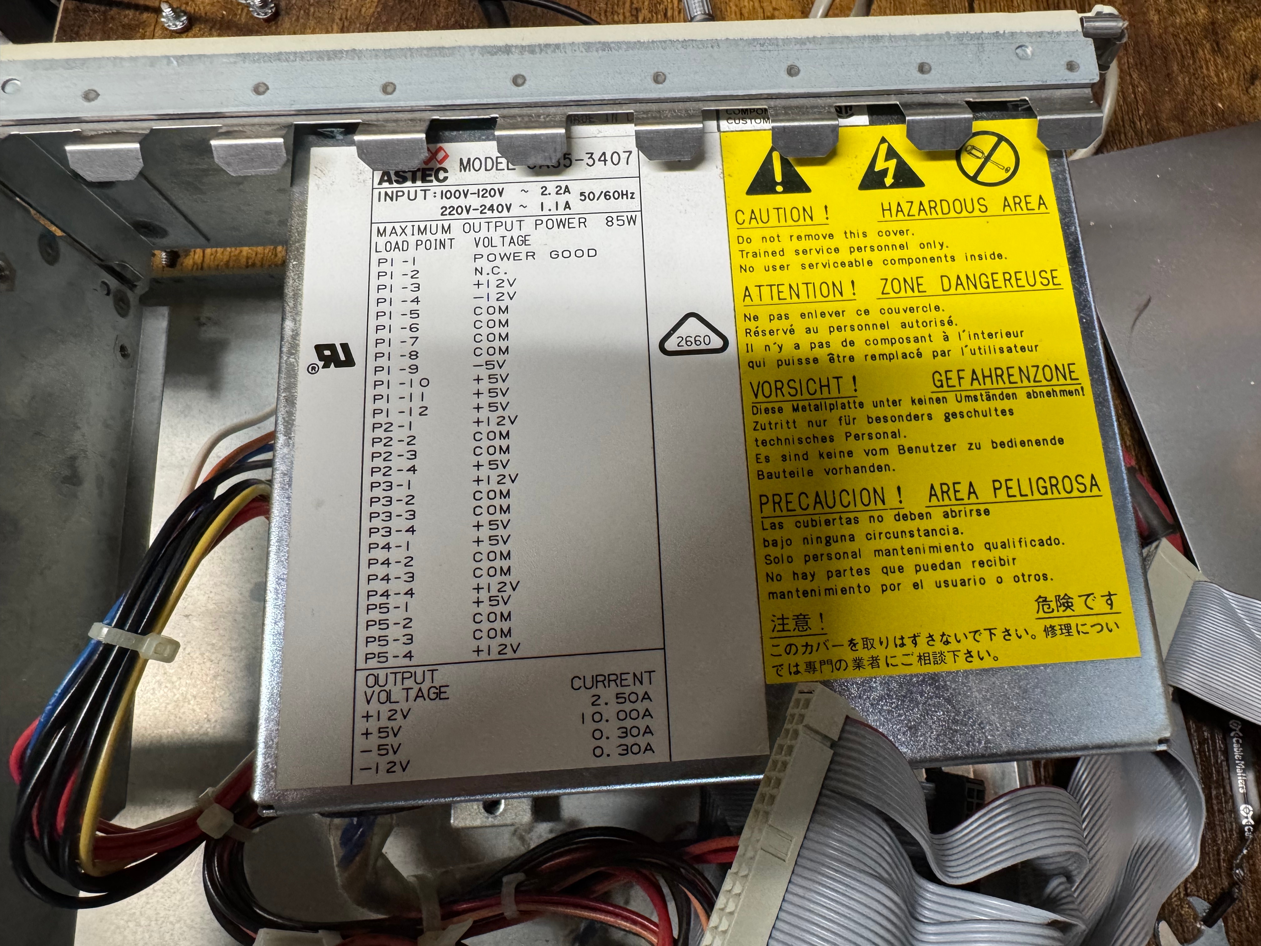
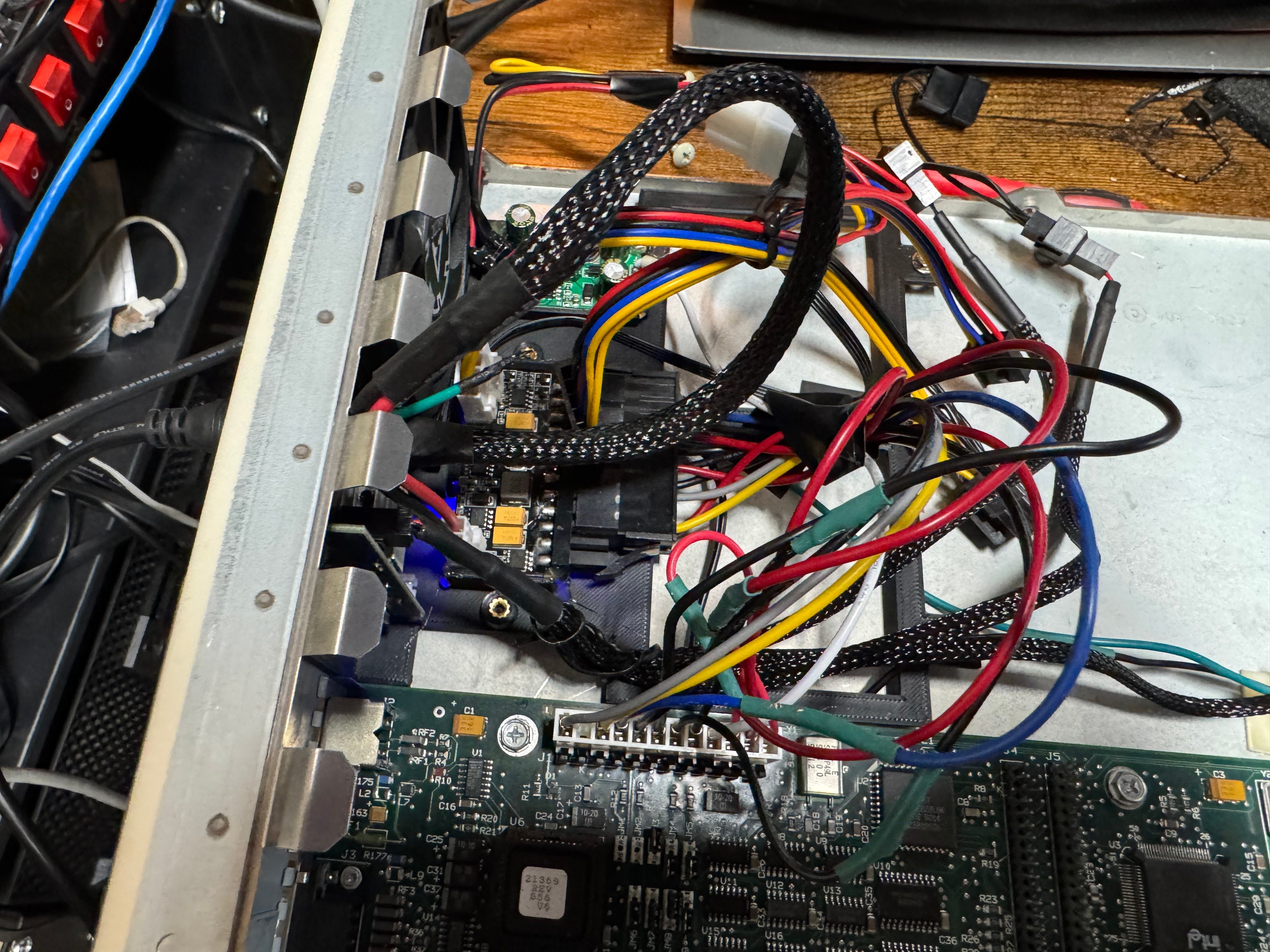
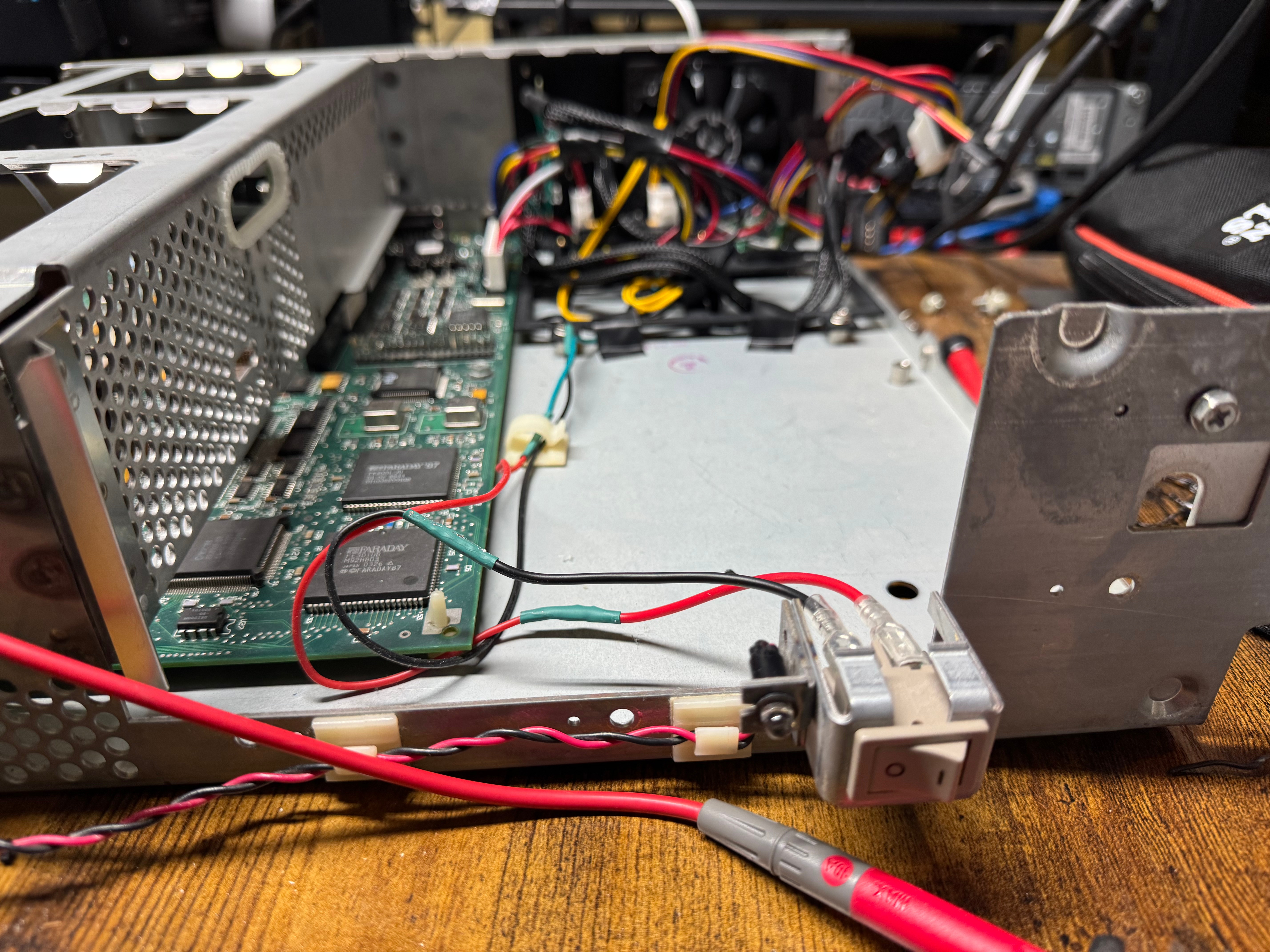
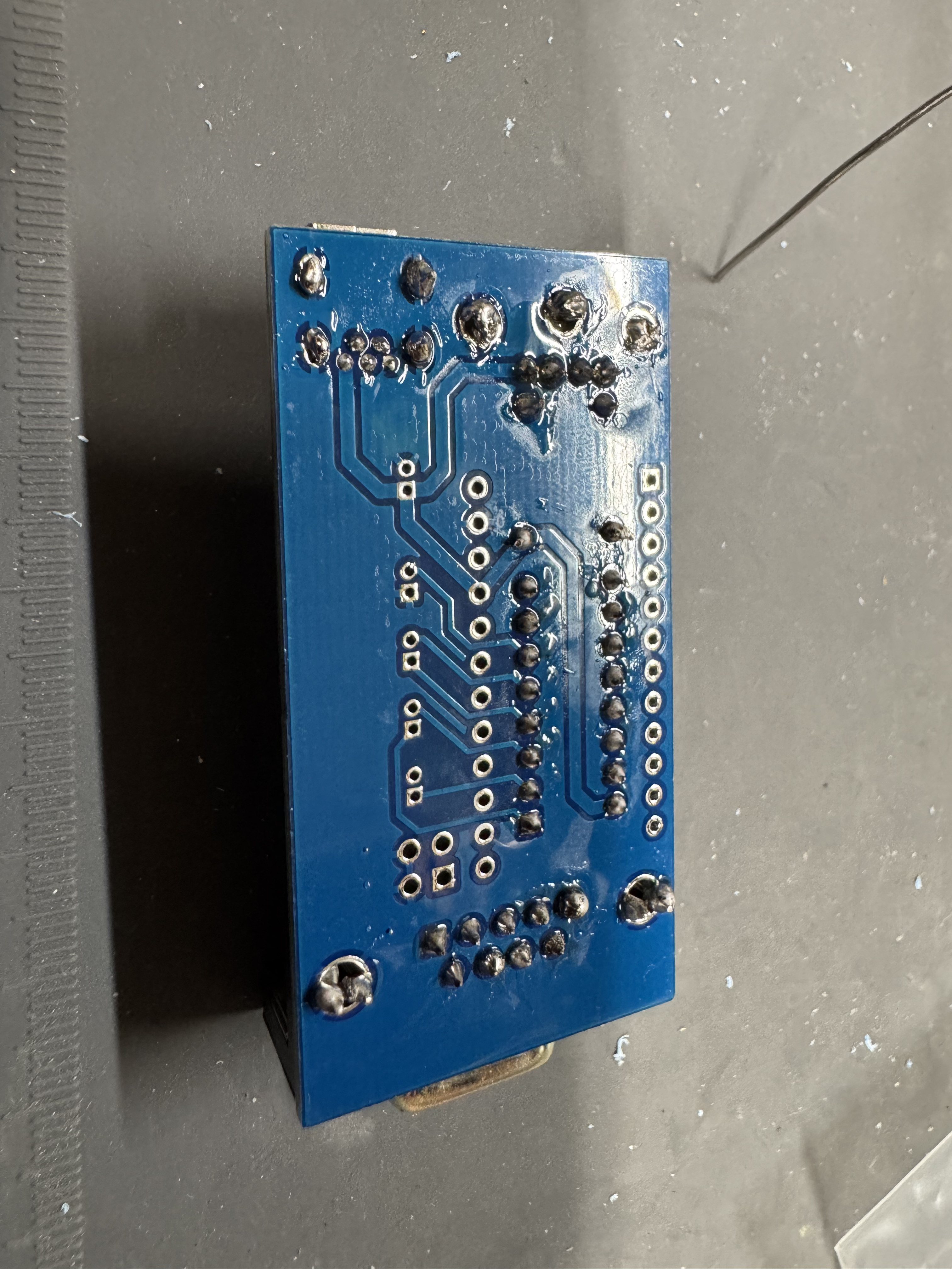
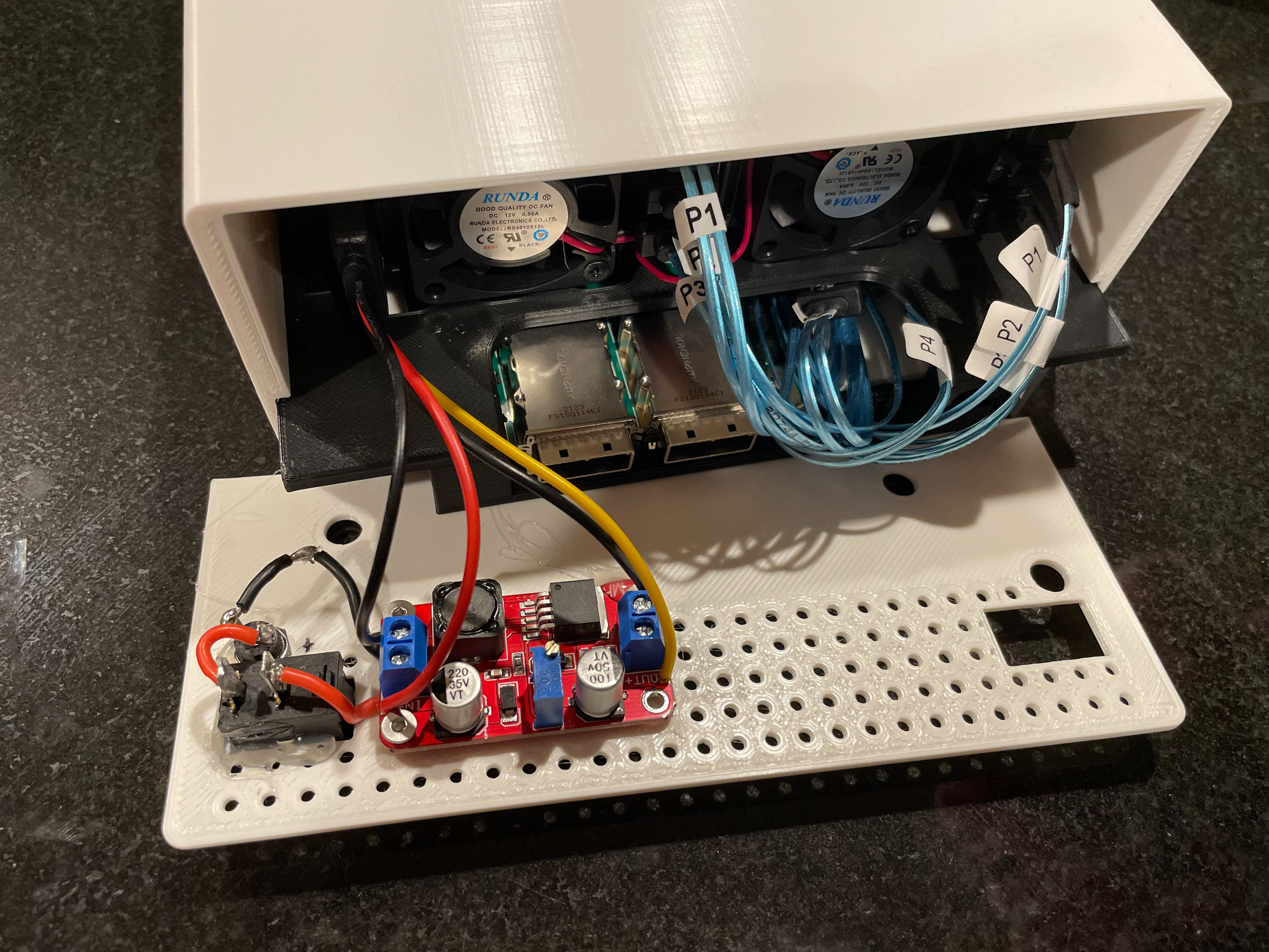
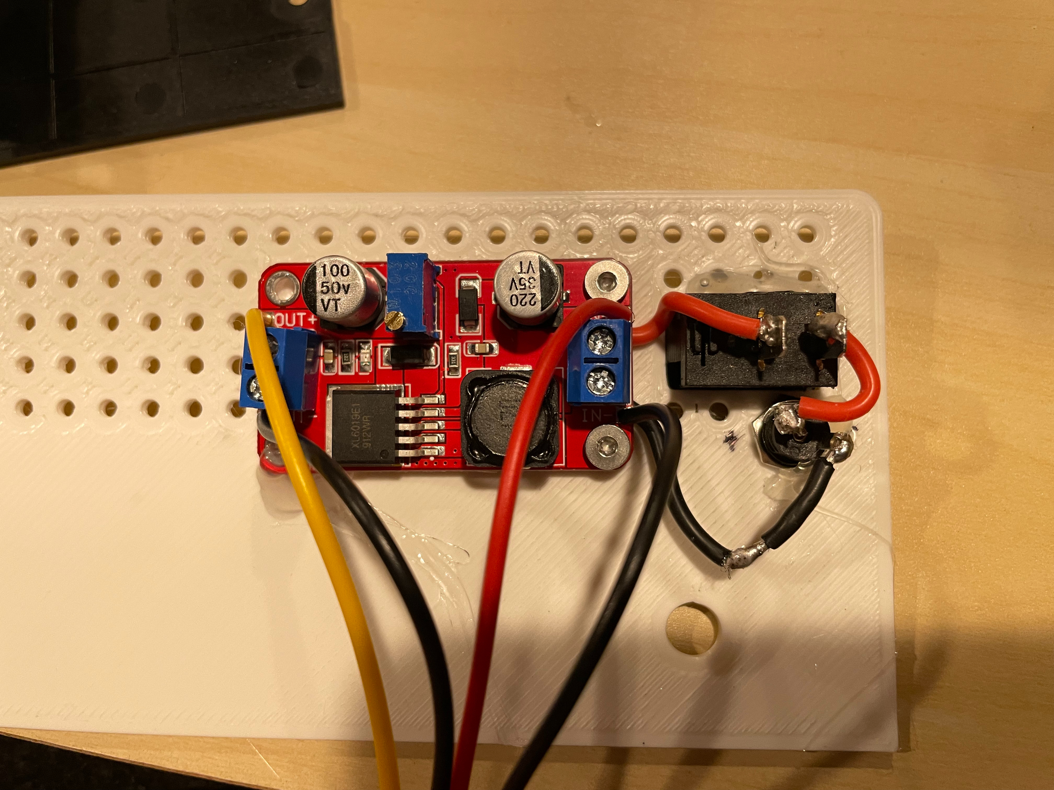
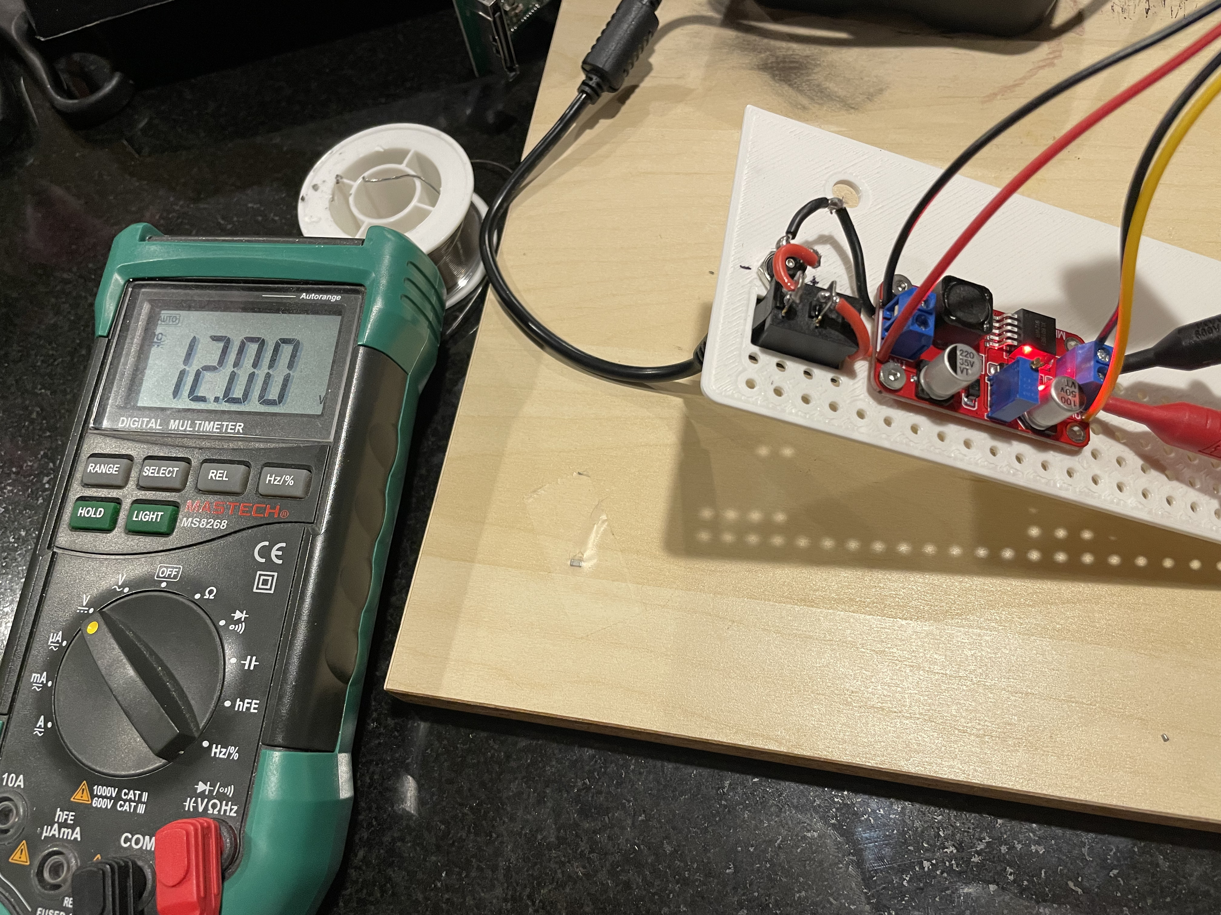
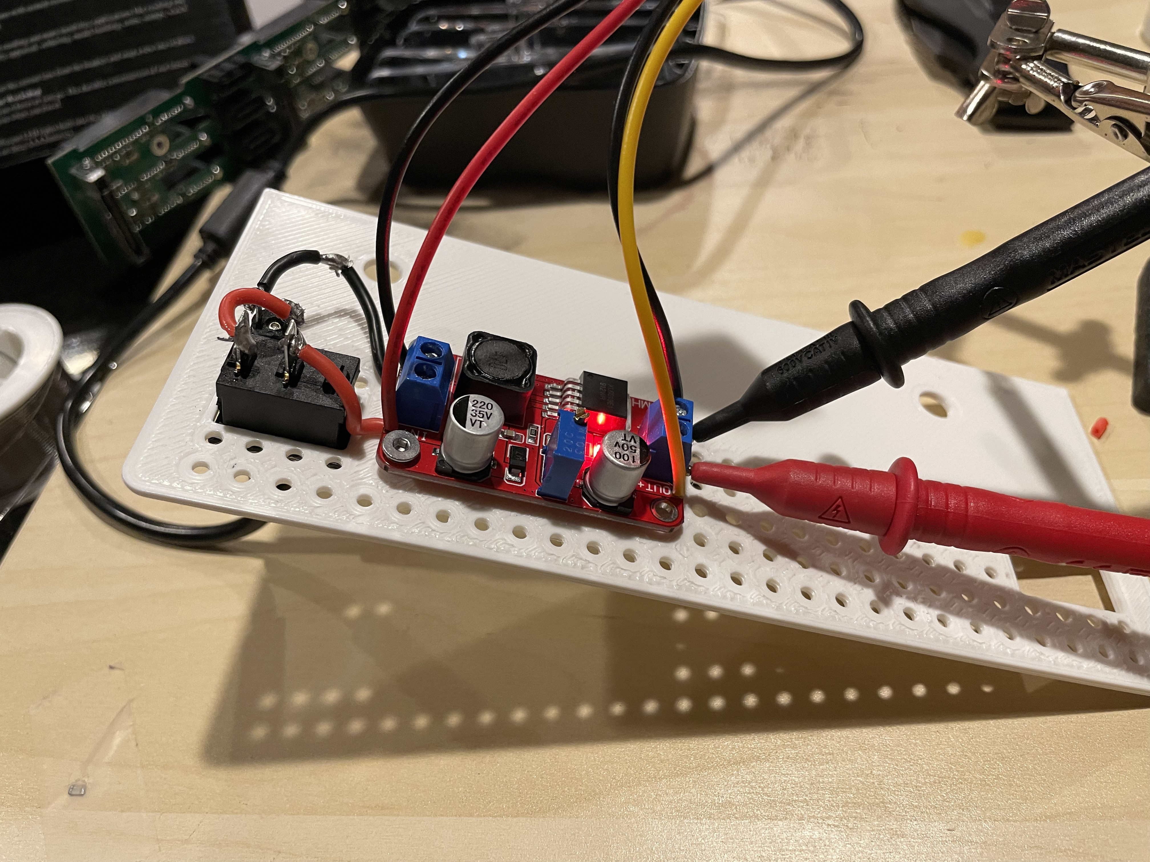
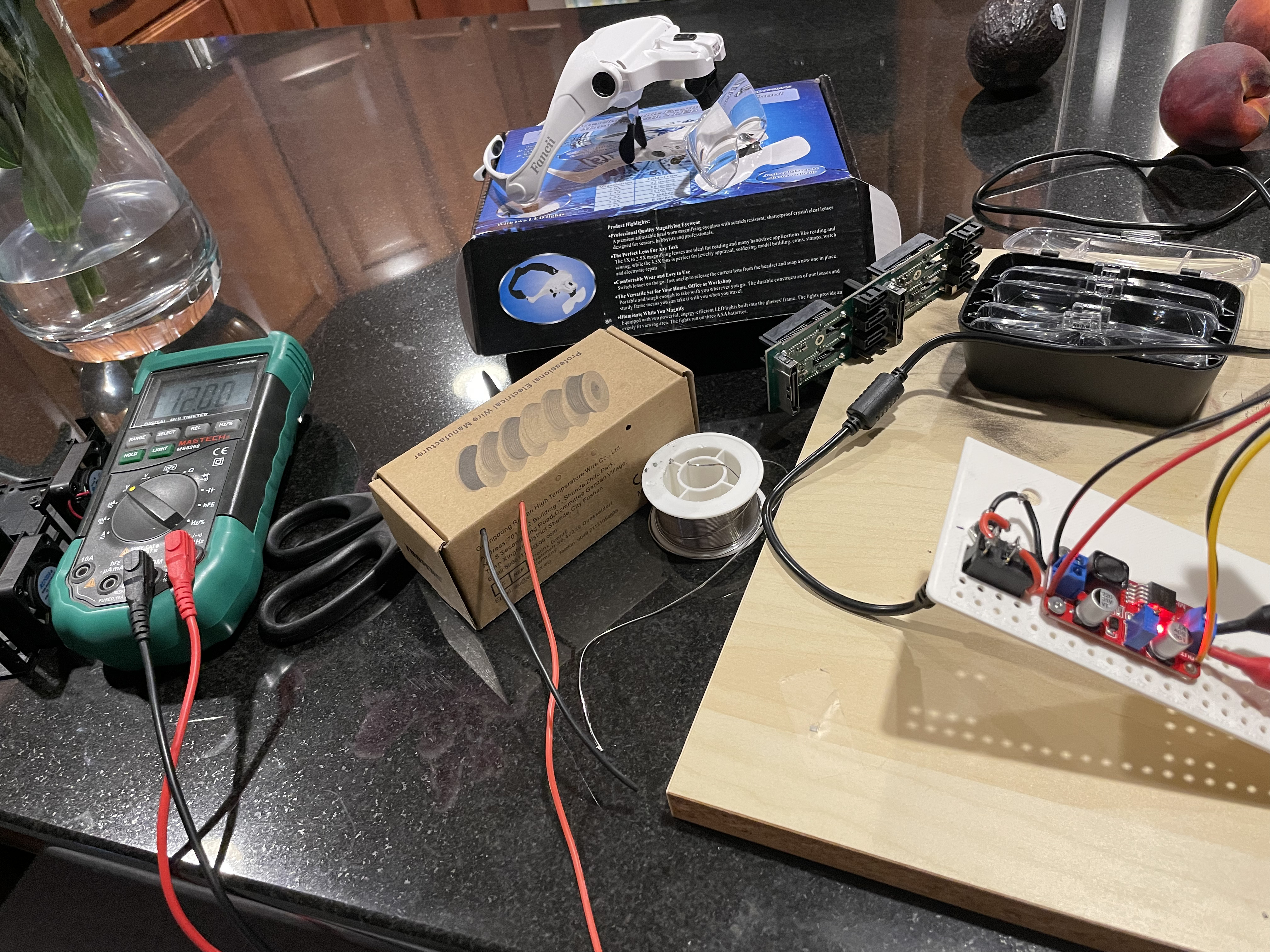
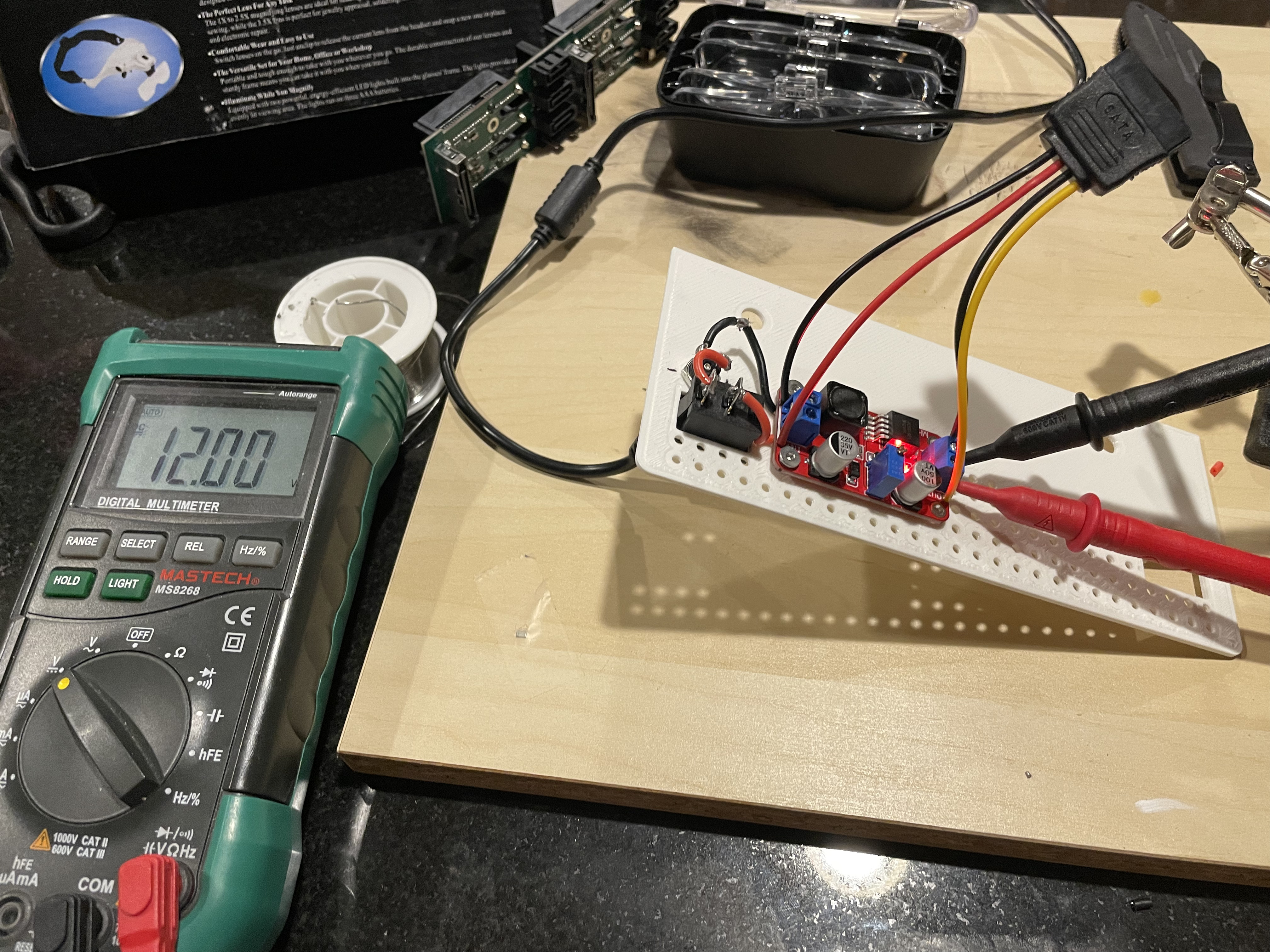
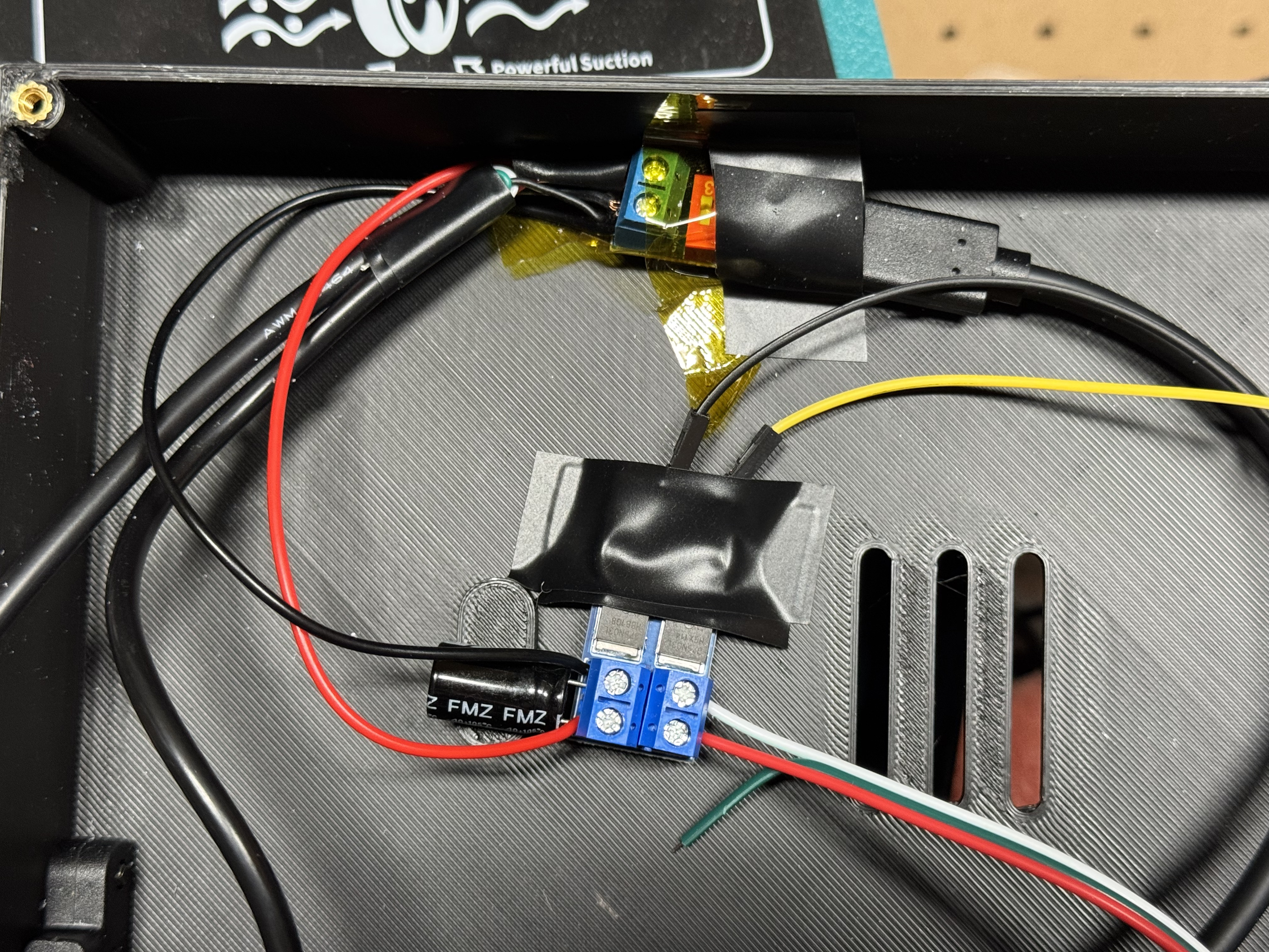
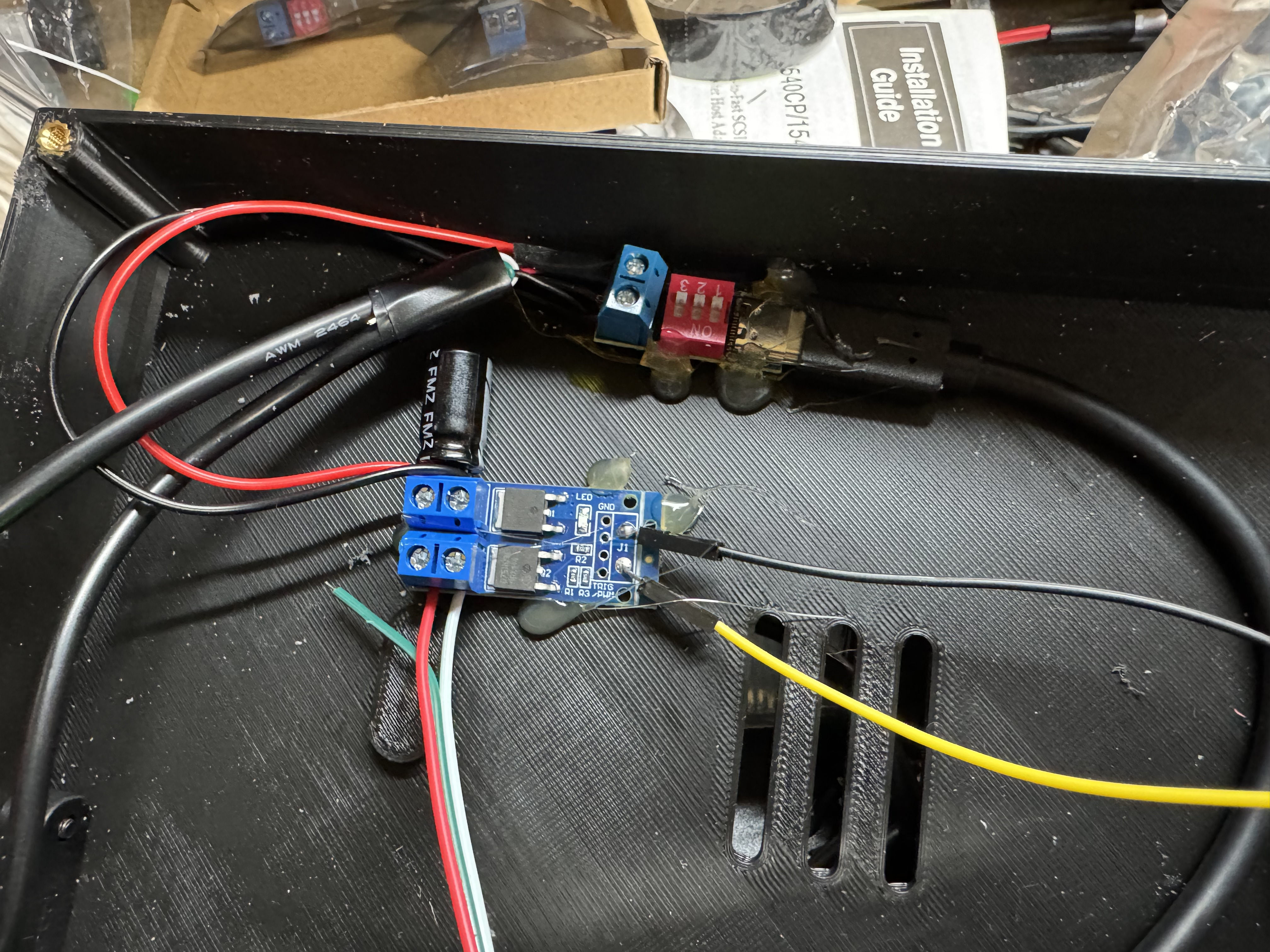
Time to wire the body. I put a USB C port in the side of the case which allowed one power plug for the device. I didn’t want to have one of those devices that had USB C but not actually USB C Power Delivery negotiations. I got a little chip that allows you to declare which voltage you want over USB C. I set that to 5V.
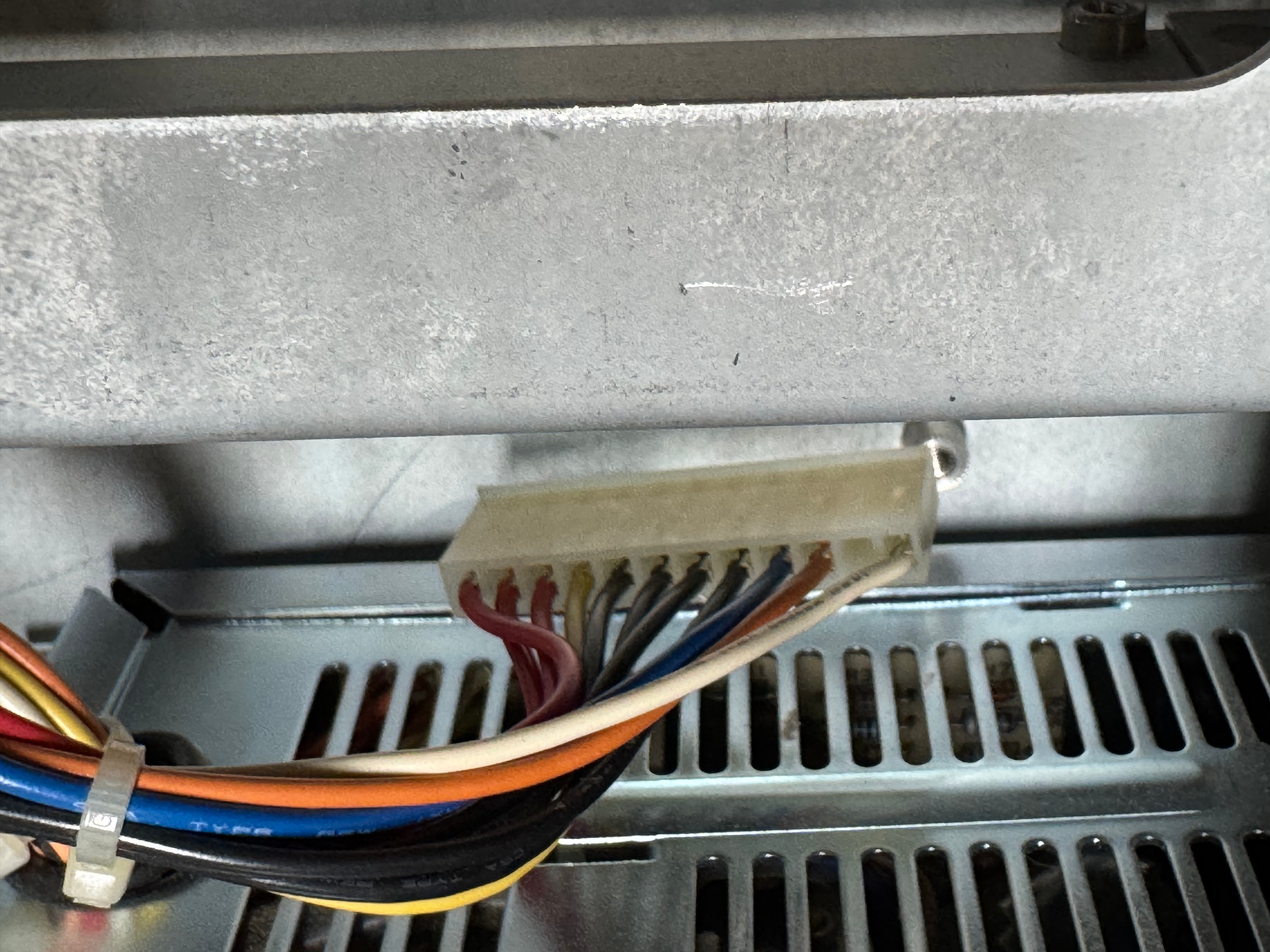
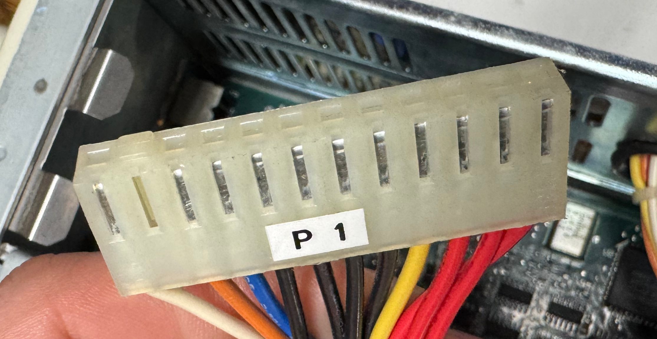
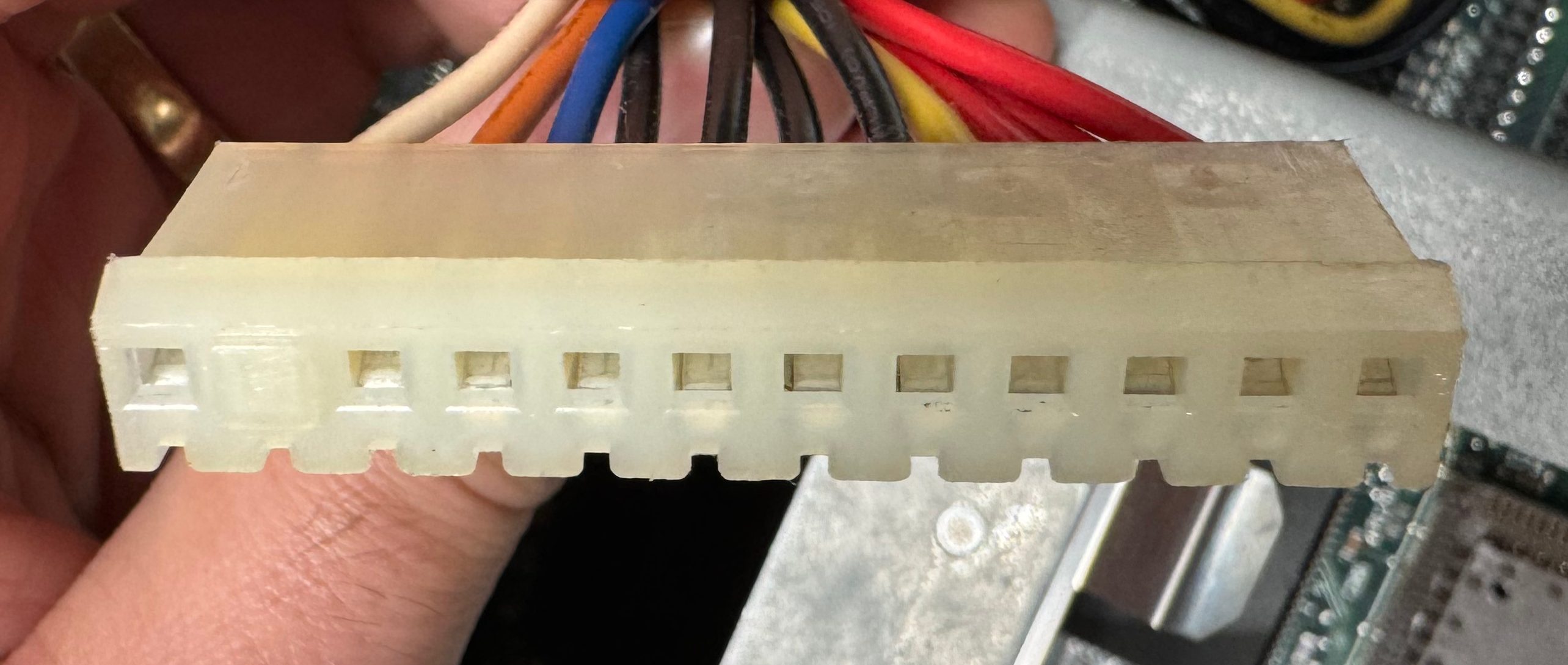
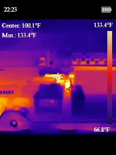
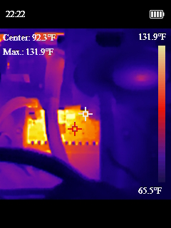
Power goes from that board, into a USB mini cable for the jukebox board, a USB C cable for the IO Board, and a pair of wires into a MOSFET. I haven’t worked with MOSFETs to control LEDs before, but I needed it to drive the LED strips I put around the screen, and behind the buttons. This actually gave me issues because (I learned later) MOSFETs are good to regulate power but also are noisy on power lines turning on and off. They caused chaos on the power line, and I ended up putting a 1000uF capacitor on the input side of the MOSFET to help smooth out the power line. Without that, the IO and jukebox boards power was so dirty they kept blinking on and off.
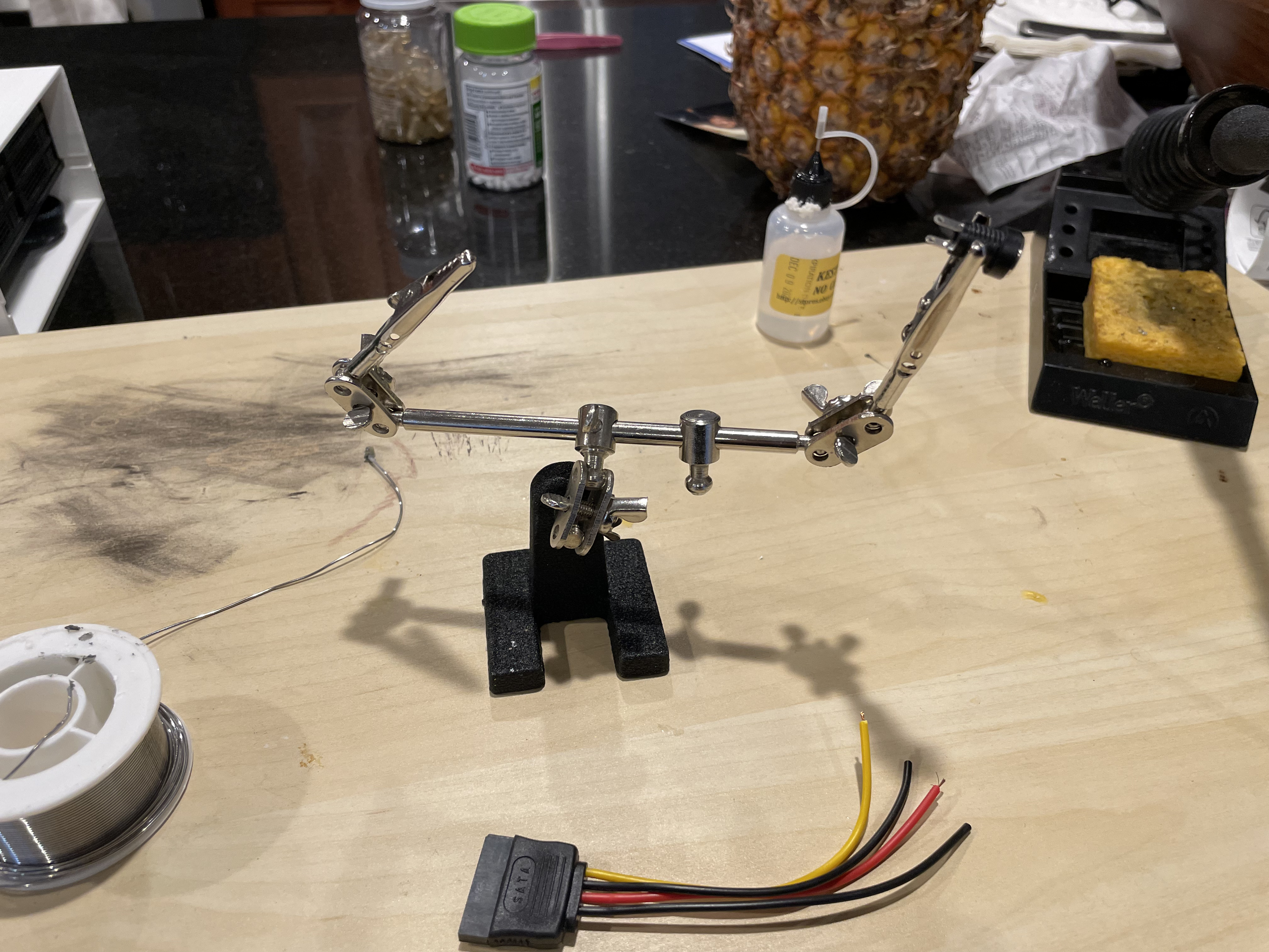
I had a bunch of quick connectors that usually are for LED lights, but I used them anywhere I may need to often connect and disconnect sub-components. If one component has more than one connector going to it, I will reverse the male/female side of the connectors to make it clear which one plugs into where. Things like PCF8575 -> IO Board, IO Board -> Jukebox board, LEDs on front panel -> MOSFET. This allowed me to quickly remove things when needed. I soldered an extra pair for the serial connection that would go between the two ESP32s.
The speakers had 4 metal anchor points around them, and I was having a hard time fitting them, so I just cut off one and it fit perfectly. The heavier speakers also helped the system stand upright, bringing a good lower point of gravity to the unit.
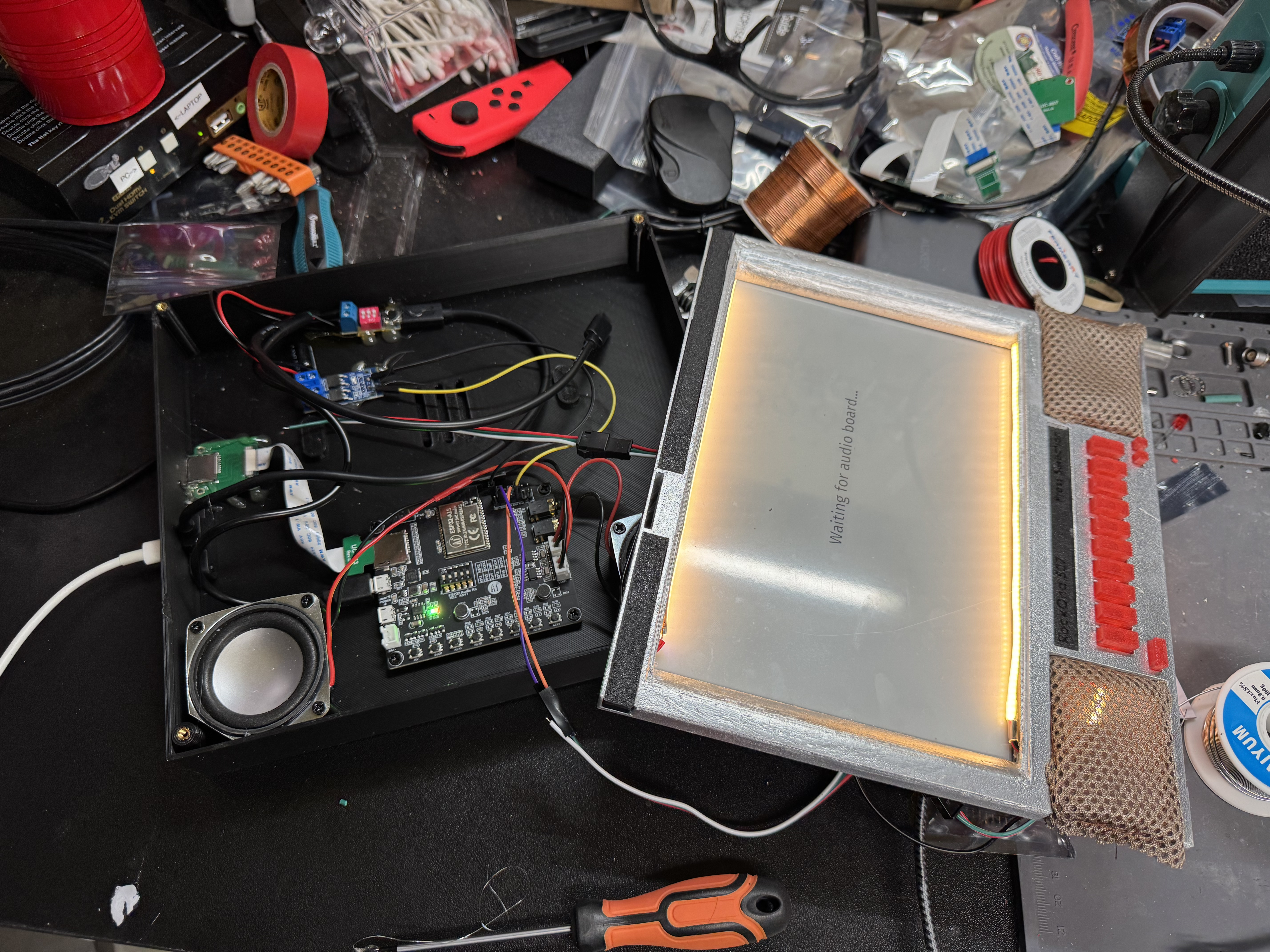
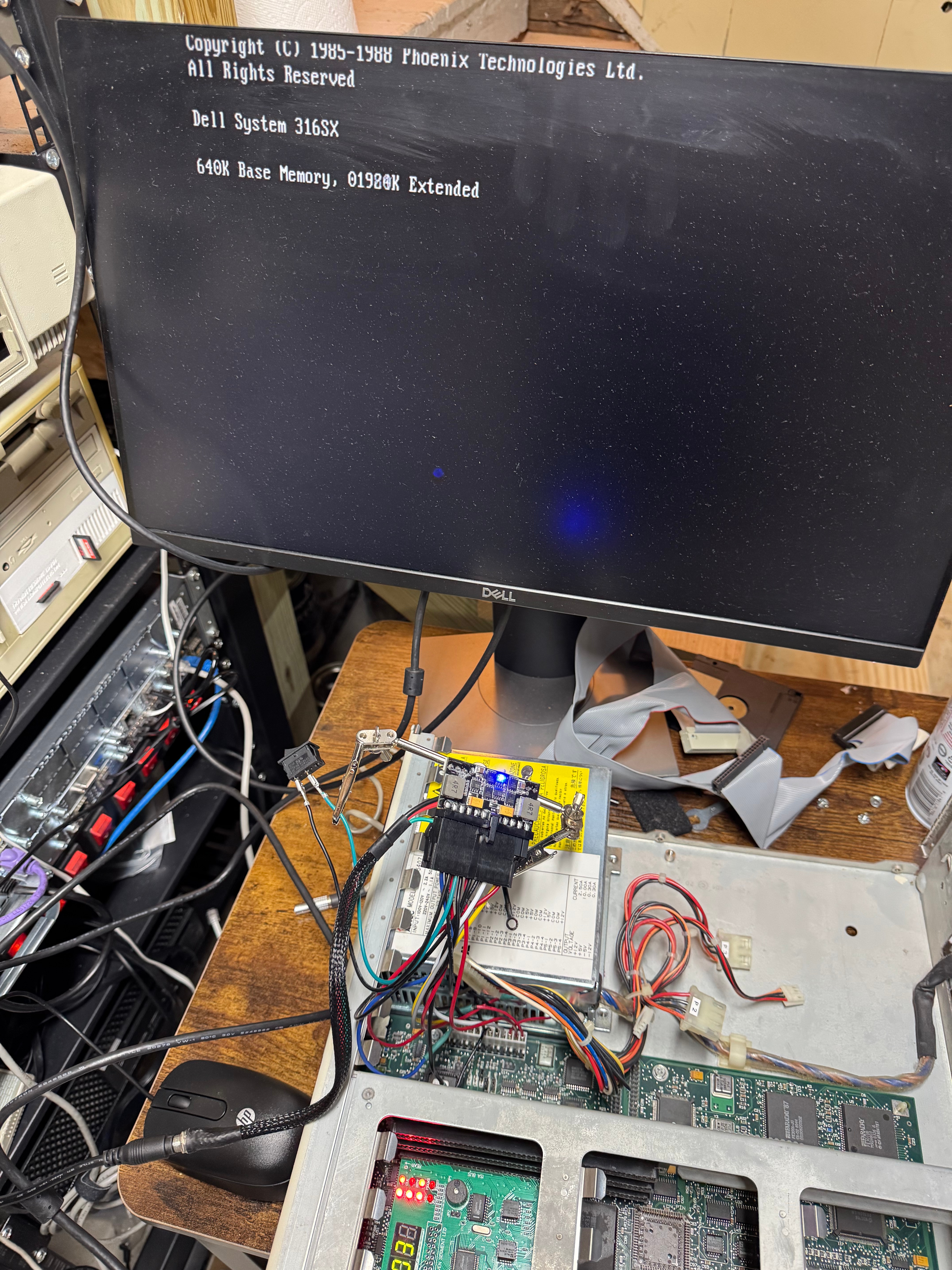
With the speakers in, and wired up, I used the heat sets and put the jukebox board in and programmed it. Then I wired that into the power sub system and connected the two ESP32s. And crazy enough, it worked! I did some tweaking from there around the buttons, and screen output, but overall, we were good!
I did have a moment where I had the IO Board ESP32 connected to my laptop, and jukebox on the normal power system, and I couldn’t get the serial line to come up. That’s when I remembered serial communication really needs 3 wires, RX, TX, and ground. I had originally planned for both ESP32s to be in the case and they would be sharing a common ground. Once I put both of them on the power from inside the case, the serial line came up!
With the project working, I went into one of the hardest parts: selecting music to add. While selecting music, I would let it play in the background. Working hands on with it I realized I wanted to add features like a queue to the screen and some feedback about which buttons you have pressed.
Wrapping Up
This project had me using a bunch of engineering things I hadn’t done before. Two ESP32s working together, working with a PCF8575 port expander, 3D printing then priming, and painting to try to get good chrome, MOSFETs, E-Ink; it was a lot of fun.
I also had ideas that could go into another version down the line: a knob on the side like the original to have more than one page of songs, a web interface for uploading songs and showing the queue, Spotify connect support (somehow). Possibly a cheaper version where you print out the song list and don’t need an E-Ink screen. I want to use these units for a while in my office and in the workshop, and then see what makes sense to add over time.
If anyone has any questions or is interested in making one and needs more information than I have here and in the repo let me know!