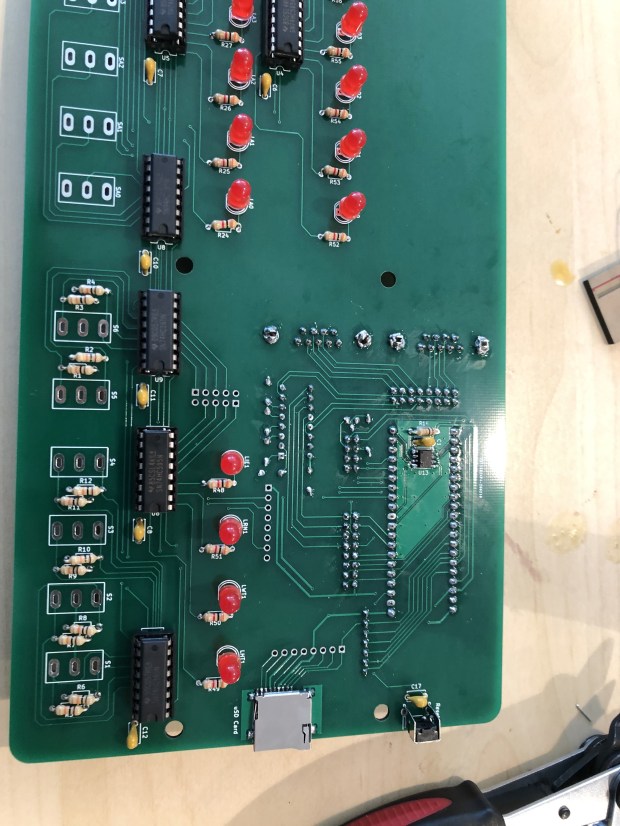
I am starting a series about my homelab and how it is all laid out. I have written this article a few times, with months in between. Each time the setup changes, but we seem to be at a stable-ish point where I will start this series. Since I wrote this whole article and now a while later am editing it, I will mark with italics and underline when present me is filling in. I think it will give a neat split of growth in the last year or so I have been working on this. Or it will make it illegible, we will see. My home setup gives me a good chance to test out different operating systems and configs in a domain environment before using that tech elsewhere like at work.
Hypervisor
Starting off with virtualization technology, I settled a while ago on Microsoft Hyper-V instead of ESXi, the main reason behind it is I already had Windows Server, and Hyper-V allows for Dynamic memory, and allocating a range of memory for a VM. When something like an AD controller is idling, it doesn’t need much memory; when it starts it may, Dynamic memory allows me to take that into account. I will say one place that has bit me later is file storage, but that will be a later post.
Original post layout 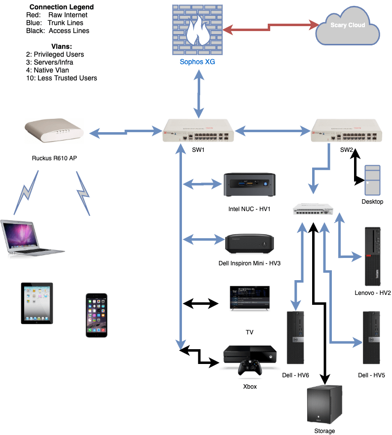
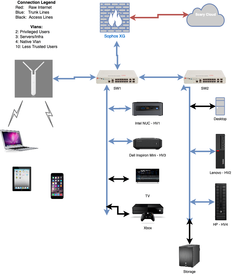
Updated Diagram

The setup is technically “router on a stick”, where the Sophos XG firewall functions as the router, and the rest of the devices hang off of that. The Sophos XG machine is a old Dell Optiplex 990 (almost 10 years old!) with an Intel quad NIC in it. That way it can do hardware offloading for most of the traffic. I intend to do posts for networking, hypervisors, file storage, domain, and more; thus I will not get too in the weeds right now on the particulars.
The file storage is a FreeNAS box recently updated to 7, 3TB HDDS. I have had this box for about over 6 years (I just looked it up in November 2020, one of the drives has 55257 hours or 6.3 years of run time on it); it is older but has worked well for me so far.
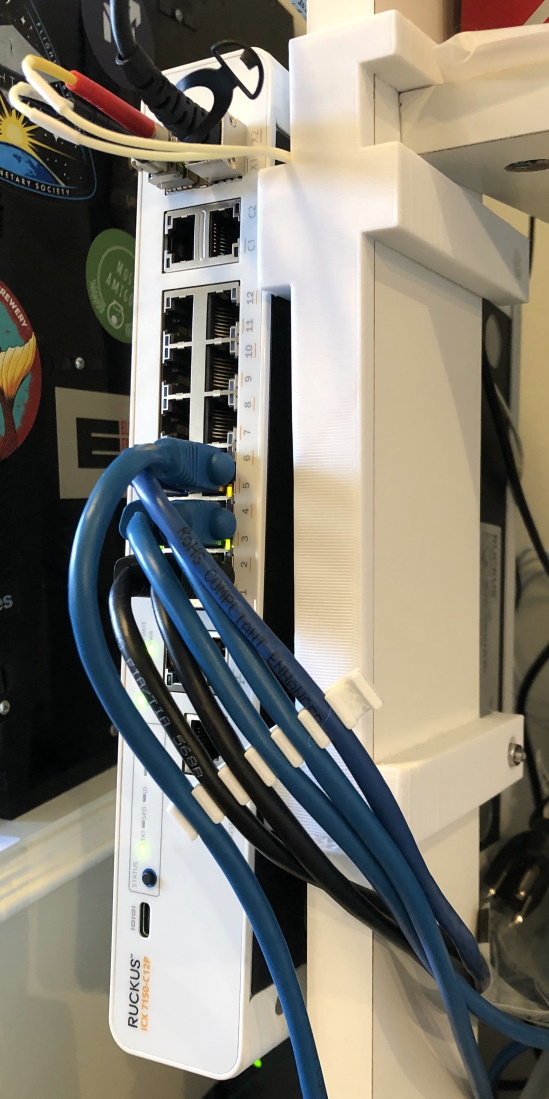
The network backbone is a new switch I really like that I was able to get 2 of off eBay; they were broken but I was able to repair them, more on that later as well. They are Brocade, now Ruckus, ICX7150-12P; 12 1GB/s POE ports, 2 additional 1GB/s uplink port, and 2, 1/10GB/s SFP/SFP+ ports. These switches can run at layer 3, but I have the layer 2 firmware on them currently. They have a fiber connection between them, before that I was using 2 Unifi APs in a bridge, that didn’t work fantastic however because A. I am in NY, B. they were only 2×2 802.11AC Wave 1, and C. I am in NY. I custom ordered (so the significant other would not get mad) a white 50m fiber cable to go around the wall of the apartment.
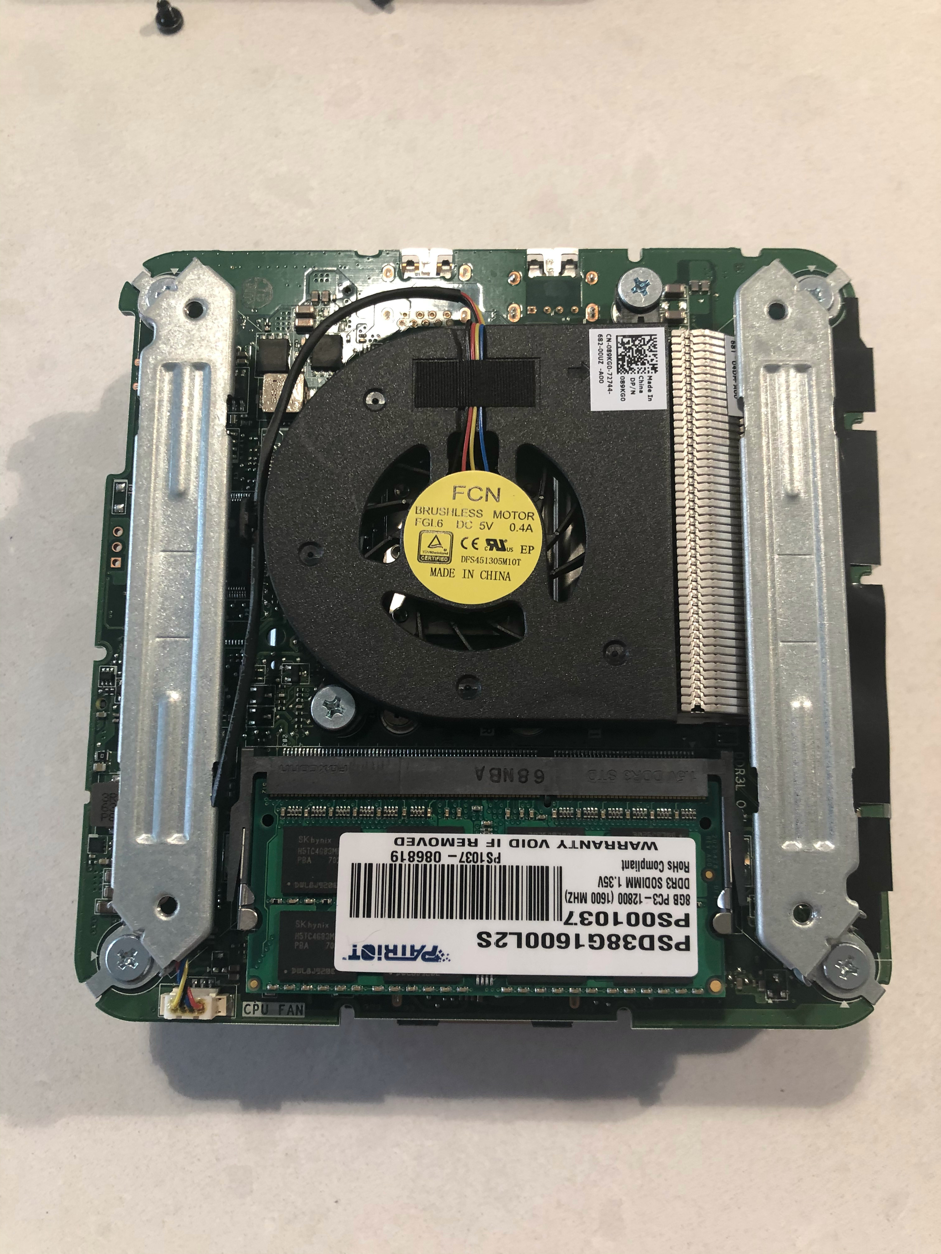
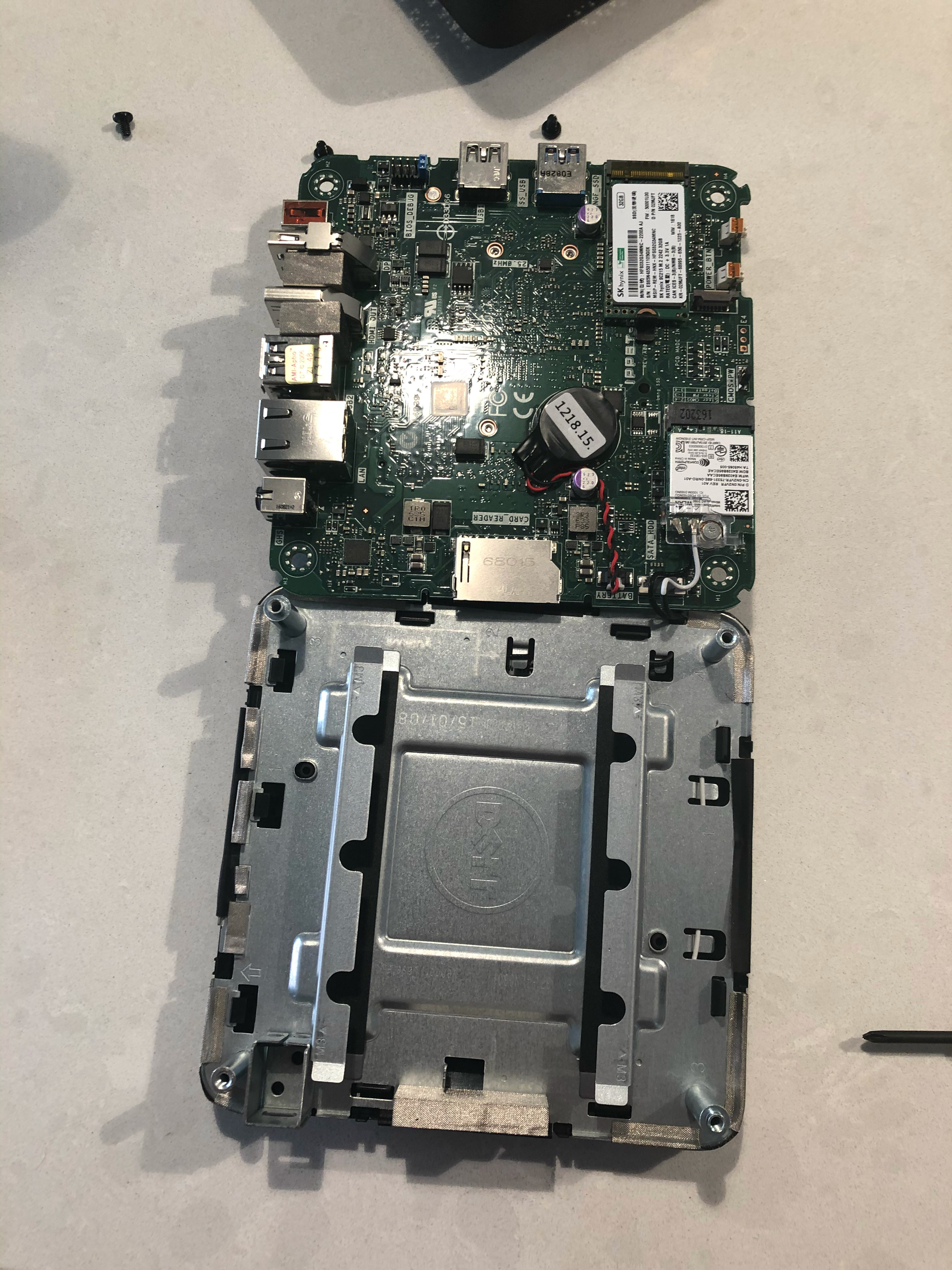
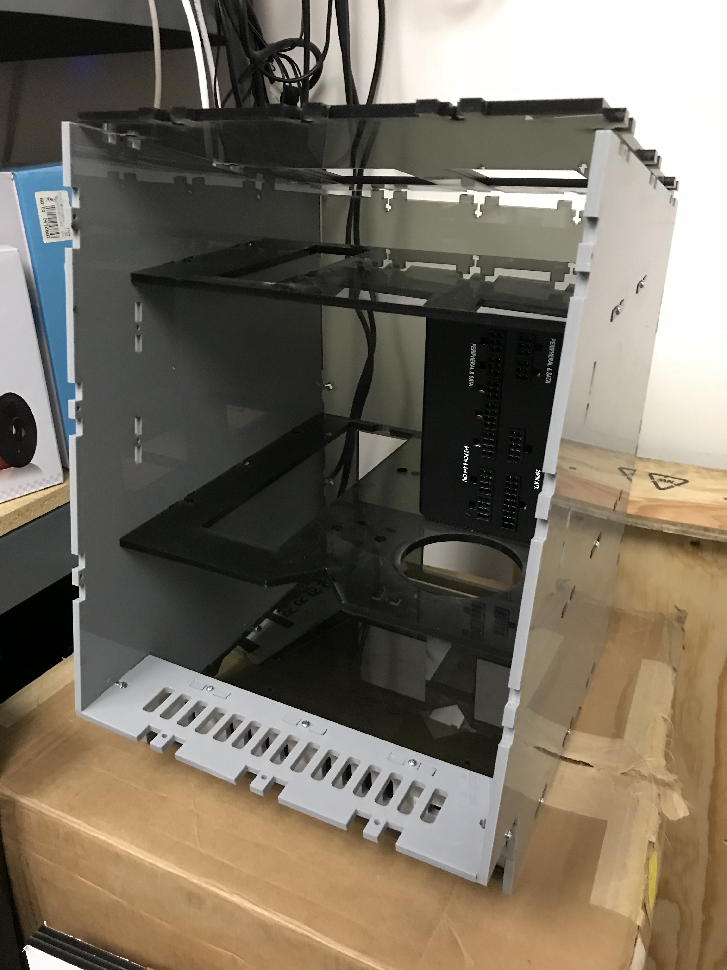
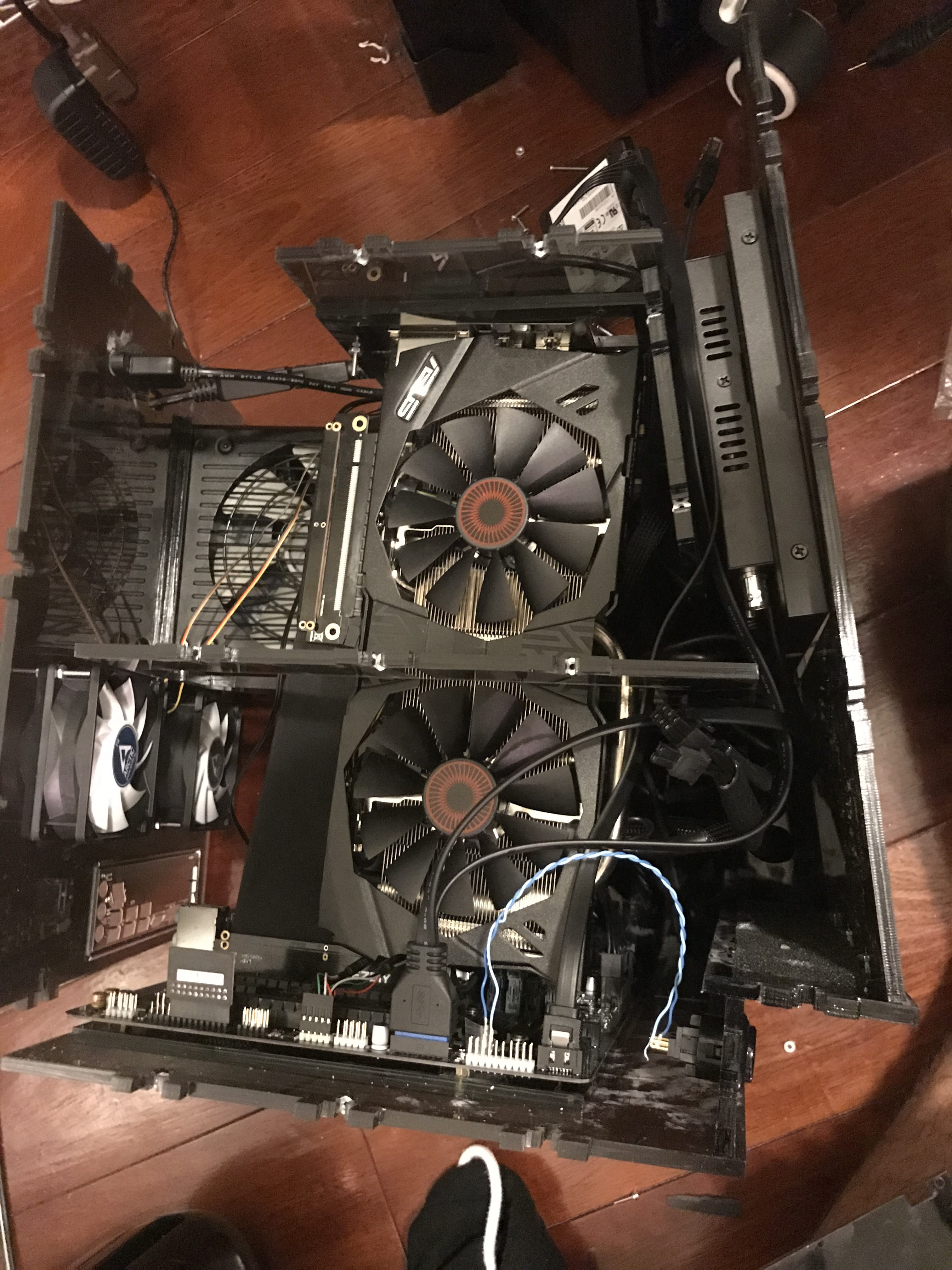
With SSDs in the hypervisor boxes (I call them HV# for short) and iSCSI storage for VMs as well, which VMs are on which host doesn’t particularly matter. Flash forward 6 months or so, since that first sentence was written, I now still use the NAS for backups, but the hypervisors are running Storage Spaces Directed and doing shared storage now. This allows the hypervisors to move move VMs around during patching or pause during a system update if they are less critical. The Intel NUC and small Dell Inspiron are much under powered compared to the mid tower hypervisors, so they run usually only 1 or 2 things. The NUC runs the primary older domain controller, and that is it. It is an older NUC that I got about 7 years ago, so its not that fast. The “servers” in the hypervisor failover cluster are a Lenovo and 2 Dell Optiplex 5050s. I like these Dells because they go for about $200 on eBay, while having a Intel 7600 i5, can support 64GB of ram, and have expansion slots for things like 10gb SFP+ cards. These machines also idle at about 30 watts, which makes the power bill more reasonable.
Some of the services I run include:
- 2 Domain Controllers (Server 2016, and 2019)
- Including Routing and Access service for RADIUS and 802.1x on wifi on wired
- Windows Admin Center Server (Windows Server 2019)
- Windows Bastion (This box does Windows Management) (Server 2019)
- Veeam Server (Server 2019)
- Unifi Controller/Unifi Video for security camera (Ubuntu)
- 3 Elastic Search boxes for ELK (CentOS 8)
- Linux Bastion (CentOS 8)
- Foreman Server (CentOS 8)
- LibreNMS (This I grew to really like) (CentOS 8)
- Nessus Server (CentOS 8)
- Jira Server (CentOS 8)
That is the general overview, I will spend the next while diving into each bit and discussing how it is configured and what I learned in doing that.